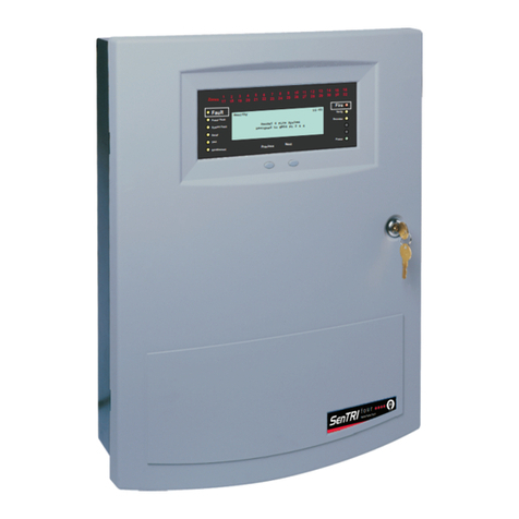
SMS Senator 2 User manual

Preface
This is the second issue of the Installation Manual for the Senator II
system. The manual covers Senator II products that are compatible with
version 3.3X software and also includes the requirements of the Low
Voltage Directive.
The manual is a guide to be read in conjunction with the recommendations
in BS5839:Part 1:1988, which is the code of practice for Fire detection and
alarm system for buildings.
Associated Documents
78930-03NM Operating Manual for Senator II
Conventions
NOTE: A note highlights important text that is normally hidden in the
main text.
CAUTION: A caution is given to prevent damage to equipment.
WARNING: A warning is given to of dangerous conditions that
may result in injury or death.

Issue Record
Section Issue Date Comments
Prelims
1 - 21
Parts
2
2
2
10/96
10/96
10/96 This second issue covers installation of
Senator II systems and network system
products that are compatible with version 3.3X
software. The second issue also covers
changes arising from LVD requirements.
The information contained herein is the property of CARADON GENT LIMITED and is supplied without liability for errors or omissions. No part of
the manual may be reproduced in any form whatsoever without prior consent of the company. Due to the on going development of the Senator II
system the information contained in the manual is subject to change without notice.

This page left intentionally blank

Senator II Supplier Details
For any queries please contact your supplier, whose details are shown
below:
Supplier name:_______________________________________________
Address:______________________________________________________
_____________________________________________________________
_____________________________________________________________
Telephone number:____________________________________________
Fax number:_________________________________________________

This page left intentionally blank

List of Contents
Notes to Installer . . . . . . . . . . . . . . . . . . . . . 1-1
EMC Compliance . . . . . . . . . . . . . . . . . . . . . 2-1
LVD Compliance . . . . . . . . . . . . . . . . . . . . . 3-1
Cable Types . . . . . . . . . . . . . . . . . . . . . . . . 4-1
Loop cables . . . . . . . . . . . . . . . . . . . . . . . . . . . . . . 4-1
Loop Cable type and Specification . . . . . . . . . . . . . . . . 4-1
Alternative Loop cable . . . . . . . . . . . . . . . . . . . . . . 4-2
Network Cables . . . . . . . . . . . . . . . . . . . . . . . . . . . . 4-2
Loop Circuit Connections . . . . . . . . . . . . . . . . 5-1
Loop Capacity . . . . . . . . . . . . . . . . . . . . . . . . . . . . 5-1
Devices (Outstations) per loop . . . . . . . . . . . . . . . . . . 5-1
Loop cable . . . . . . . . . . . . . . . . . . . . . . . . . . . . . . . 5-2
Cable separation . . . . . . . . . . . . . . . . . . . . . . . . . . . 5-2
Loop Coverage . . . . . . . . . . . . . . . . . . . . . . . . . . . . 5-2
Spur circuits . . . . . . . . . . . . . . . . . . . . . . . . . . . . . . 5-2
Lightning protection . . . . . . . . . . . . . . . . . . . . . . . . . 5-2
Control Panel connections . . . . . . . . . . . . . . . . . . . . . . 5-4
2-way device . . . . . . . . . . . . . . . . . . . . . . . . . . . . . . 5-5
3-way device . . . . . . . . . . . . . . . . . . . . . . . . . . . . . . 5-5
Slave (Indicator) LED Unit . . . . . . . . . . . . . . . . . . . . . 5-6
SlaveRelay Unit . . . . . . . . . . . . . . . . . . . . . . . . . . . . 5-6
Standalone System Installation . . . . . . . . . . . . . 6-1
78500-02NM Fire Alarm Control Panel Set . . . . . . . . . . . . 6-1
Contents
78910-03NM Issue 2_10/96 Senator II Installation Manual

78500-82NM Fire Alarm Control Panel . . . . . . . . . . . . . 6-1
Fuses and locations . . . . . . . . . . . . . . . . . . . . . . . . . . 6-1
.78510-02NM Battery Unit . . . . . . . . . . . . . . . . . . . . . . 6-5
Fuses and locations . . . . . . . . . . . . . . . . . . . . . . . . . . 6-5
Fire Control Panel Connections . . . . . . . . . . . . . . . . . . . 6-7
Mains Connection . . . . . . . . . . . . . . . . . . . . . . . . . 6-7
Loop, Master Alarms and Fire/Fault Relay
Connections . . . . . . . . . . . . . . . . . . . . . . . . . . . . 6-7
78600-01NM Fire Alarm Repeat Panel Set . . . . . . . . . . . . . 6-8
78600-82NM Fire Alarm Repeat Panel . . . . . . . . . . . . . . 6-8
Fuses and locations . . . . . . . . . . . . . . . . . . . . . . . . . . 6-8
Fire Repeat Panel Connections . . . . . . . . . . . . . . . . . . . 6-10
Flushing Fixing Panels . . . . . . . . . . . . . . . . . . . . . . . . 6-11
78200-01NM Terminal Plate . . . . . . . . . . . . . . . 7-1
Terminal Plate installation . . . . . . . . . . . . . . . . . . . . . 7-1
Fire sensors . . . . . . . . . . . . . . . . . . . . . . . . 8-1
Fitting a sensor head to terminal plate . . . . . . . . . . . . . . . 8-2
Removal of sensor head from terminal plate . . . . . . . . . . . . 8-3
To assemble a sensor head . . . . . . . . . . . . . . . . . . . . . . 8-5
78260-01NM Semi flush mounting kit . . . . . . . . . . 9-1
T-breaker and slave units . . . . . . . . . . . . . . . . 10-1
78260-01NM Duct Sensor . . . . . . . . . . . . . . . . 11-1
Manual Call Points . . . . . . . . . . . . . . . . . . . . 12-1
Surface Fixing . . . . . . . . . . . . . . . . . . . . . . . . . . . . . 12-1
Semi-Flush Fixing . . . . . . . . . . . . . . . . . . . . . . . . . . . 12-3
Contents
Senator II Installation Manual 78910-03NM Issue 2_10/96

Testing . . . . . . . . . . . . . . . . . . . . . . . . . . . . . . . . . 12-3
Alarm Sounders . . . . . . . . . . . . . . . . . . . . . 13-1
78277-01NM Repeat Sounder . . . . . . . . . . . . . . . . . . . . 13-2
78301-01NM Fire Alarm Interface Unit
(Mains powered) . . . . . . . . . . . . . . . . . . . . . 14-1
Fuses and locations . . . . . . . . . . . . . . . . . . . . . . . . . . 14-1
78321-01NM Fire alarm interface unit
(Loop powered) . . . . . . . . . . . . . . . . . . . . . . 15-1
Fuses and Locations . . . . . . . . . . . . . . . . . . . . . . . . . 15-1
78345-06NM Power Supply Unit . . . . . . . . . . . . 16-1
Fuses and Locations . . . . . . . . . . . . . . . . . . . . . . . . . 16-1
78310-01NM Loop Powered Zone Module . . . . . . . 17-1
78315-01NM Single Channel Interface
(Loop Powered) . . . . . . . . . . . . . . . . . . . . . . 18-1
Network Overview . . . . . . . . . . . . . . . . . . . . 19-1
Network Capacity . . . . . . . . . . . . . . . . . . . . . . . . . . . 19-1
Network Cables . . . . . . . . . . . . . . . . . . . . . . . . . . . . 19-1
Schematic Diagram . . . . . . . . . . . . . . . . . . . . . . . . . . 19-1
Network Installation . . . . . . . . . . . . . . . . . . . 20-1
Fuses and Locations . . . . . . . . . . . . . . . . . . . . . . . . . 20-1
78520-01NM Network Interface . . . . . . . . . . . . . . . . . . . 20-1
Network Wiring . . . . . . . . . . . . . . . . . . . . . . 21-1
78500 Control Panel to 78520 Network Interface . . . . . . . . . 21-1
Contents
78910-03NM Issue 2_10/96 Senator II Installation Manual

78520 Network Interface to 78520 Network Interface . . . . . . . 21-2
Senator II . . . . . . . . . . . . . . . . . . . . . . . . . 22-3
Introduction . . . . . . . . . . . . . . . . . . . . . . . . . . . . . . 22-3
Control and indicating equipment . . . . . . . . . . . . . . . . . . 22-3
Cards . . . . . . . . . . . . . . . . . . . . . . . . . . . . . . . . . 22-4
Sensors, terminal plate and Accessories . . . . . . . . . . . . . . . 22-4
Alarm sounders . . . . . . . . . . . . . . . . . . . . . . . . . . . . 22-5
Manual call points (MCP) . . . . . . . . . . . . . . . . . . . . . . 22-5
Interfaces . . . . . . . . . . . . . . . . . . . . . . . . . . . . . . . 22-5
Manuals & Accessories . . . . . . . . . . . . . . . . . . . . . . . . 22-6
Contents
Senator II Installation Manual 78910-03NM Issue 2_10/96

List of Figures
Figure 2-1 Cable termination . . . . . . . . . . . . . . 2-3
Figure 5-1 Typical fire alarm system . . . . . . . . . . 5-3
Figure 5-2 Connections to the Control Panel . . . . . . 5-4
Figure 5-3 Connecting a 2-way device . . . . . . . . . . 5-5
Figure 5-4 Connecting a 3-way device . . . . . . . . . . 5-5
Figure 5-5 Connecting a slave Indicator unit . . . . . . 5-6
Figure 5-6 Connecting slave relay unit . . . . . . . . . 5-6
Figure 6-1 Control Panel with the door open . . . . . . 6-2
Figure 6-2 Control Panel Back box shown without door 6-3
Figure 6-3 Connection of Battery cable assembly . . . 6-4
Figure 6-4 Close fitting the Panel and Battery Unit . . 6-5
Figure 6-5 Control Panel Mains connection details . . 6-7
Figure 6-6 Control Panel cable connection points . . . 6-7
Figure 6-7 Repeat Panel back box . . . . . . . . . . . . 6-9
Figure 6-8 Repeat panel connection points . . . . . . . 6-10
Figure 6-9 Flush fixing the Control or Repeat Panel . . 6-11
Figure 7-1 78200-01NM Terminal Plate . . . . . . . . 7-1
Figure 7-2 Fixing the terminal plate to a ceiling tile . . 7-2
Figure 7-3 Terminal Plate connections . . . . . . . . . 7-2
Figure 7-4 Wiring the terminal plate . . . . . . . . . . 7-2
Contents
78910-03NM Issue 2_10/96 Senator II Installation Manual

Figure 8-1 Fitting a sensor head to terminal plate . . . 8-2
Figure 8-2 Removal of the chamber module . . . . . . 8-3
Figure 8-3 Removal of electronics from terminal plate 8-4
Figure 8-4 Fitting together chamber and electronics . 8-5
Figure 9-1 Cutouts for lugs . . . . . . . . . . . . . . . 9-1
Figure 9-2 Flush kit installation . . . . . . . . . . . . . 9-2
Figure 10-1 T-breaker and slave units . . . . . . . . . 10-1
Figure 10-2 Fitting a t-breaker or slave unit . . . . . . 10-2
Figure 11-1 Duct Sensor fixing and connections . . . . 11-2
Figure 12-1 Manual Call Point parts . . . . . . . . . . 12-2
Figure 13-1 Alarm Sounder fixing and connections . . 13-1
Figure 14-1 Interface Unit with the door open . . . . . 14-1
Figure 14-2 Interface unit with the door open . . . . . 14-2
Figure 14-3 Connections Details . . . . . . . . . . . . . 14-3
Figure 15-1 Interface unit fixing and connections . . . 15-1
Figure 15-2 Line module internal connection details . 15-2
Figure 16-1 Supply Unit fixing details . . . . . . . . . 16-1
Figure 16-2 PSU to interface unit connections . . . . . 16-2
Figure 17-1 Loop powered zone module
with lid removed . . . . . . . . . . . . . . . . . . . . . 17-1
Figure 18-1 Single Channel Interface (lid removed) . . 18-1
Contents
Senator II Installation Manual 78910-03NM Issue 2_10/96

Figure 19-1 Senator II Network Schematic . . . . . . . 19-1
Figure 20-1 Network Interface Fixing and Connections20-1
Figure 21-1 Control Panel to . . . . . . . . . . . . . . . 21-1
Figure 21-2 Network Interface to . . . . . . . . . . . . 21-2
Contents
78910-03NM Issue 2_10/96 Senator II Installation Manual

This page left intentionally blank
Contents
Senator II Installation Manual 78910-03NM Issue 2_10/96

Notes to Installer
The manual contains fixing and wiring information to cover the installation
of the Senator II system, both Standalone and Network.
Installation
requirements It is recommended that the installer follows the general requirements of
BS5839:Part 1:1988, which is the code of practice relating to the fire
detection and alarm systems for buildings. The relevant parts of the Institute
of Electrical Engineers Wiring Regulations 16th edition must also be
followed.
Second fix
installation To prevent the possibility of damage or dirt degrading the performance or
appearance of the Senator II products, the installation of second fix items
should be delayed until all major building work in the area is complete (e.g.
clearing and sweeping).
Fixture and
fittings It is the installers responsibility to provide adequate fixtures and fittings for
the type of construction surface onto which a product is to be installed,
whilst utilising the fixing points on the respective product. As an aid to this
decision, the weight and overall size of each full assembly together with
implications on cable entries and routing should be taken into consideration.
NOTE: All these procedures assume that the cable, glands, steel boxes
(BESA boxes) and other related accessories are provided by the installer.
Location The installer should acquire site specific information from the interested
parties, for details on the location of products for installation. The acquired
information together with this guide and the relevant standards should be
used to assist the work.
Each product assembly can be identified from its package label. The
contents of all packages should be checked for any discrepancies.
Fire sensor
covers Each fire sensor may be supplied with a plastic dust cover. If supplied then
the dust cover must be fitted to prevent dust and dirt from the building
work from contaminating the sensor.
Notes to Installer Installation requirements
78910-03NM Issue 2_10/96
1-1
Senator II Installation Manual

Parts for later
installation All unused parts should be retained in their respective container for safe
keeping until required.
NOTE: The installation of all outstanding parts is usually carried out
during Commissioning of the System.
Loop earth
continuity To maintain earth continuity on a loop, the loop cable screen must be
connected through each system device on the loop, whether the earth is
connected to a device or not
NOTE: The network cable screen is earthed at one end only.
Mains supply Mains supply to fire alarm control and indicating equipment must be via an
unswitched fused spur unit.
The fused spur isolator cover should be red and marked:
FIRE ALARM - DO NOT SWITCH OFF
Each of the fire alarm equipments’ fused spur units must be fed from a
dedicated switch or protective device at the local mains supply distribution
board.
Mains and
battery supply
connections
The mains and battery supply cables must be installed to the stage to
facilitate the power up for commissioning.
WARNING: Where mains cable are to remain disconnected,
their tail ends must be insulated to prevent dangerous
conditions arising in the event of accidental switching On of
the mains supply
Cable
termination
and connection
Terminate each cable at the entry point to the enclosure, using the cable
manufacturer’s recommended techniques.
Where the cable is required to be connected, ensure it is secure to the
respective terminal.
Where the cable is not required to be connected, leave 400mm (unless
otherwise specified) tail wire length and mark each core identifying its
final point of connection.
Wiring test CAUTION: DO NOT undertake high voltage insulation tests
WITH THE CABLES CONNECTED to their terminals. Such a
test may damage the electronics circuitry in loop devices and
panels.
Parts for later installation Notes to Installer
Senator II Installation Manual
1-2
78910-03NM Issue 2_10/96

EMC Compliance
Installation guidelines for compliance with the
requirements of the Electromagnetic
Compatibility (EMC) Directive
Introduction These guidelines should be followed to meet the requirements of the EMC
directive in force within the European Union, to prevent the reception
and emission of electromagnetic interference into and out of the analogue
addressable fire detection and alarm system.
Products The products covered by these guidelines are listed under EMC compliant
products, see list on the last page of this section.
Code of
practice The installer must follow BS7671 : 1992 Requirements for Electrical
installations, IEE wiring regulations 16th edition if installation is in the United
Kingdom, UK.
Cables The following cables have been tested against EMC directives for use with
with fire detection and alarm applications:
(see also the Cable types part of Installation manual for further information)
For loop circuit, battery connection and master alarm circuit wiring:
•Mineral Insulated Copper Cable (MICC)
•FIRETUF OHLS Cable type: FTZ2E1.5
For network interface to network interface or control panel to
network interface wiring:
•Mineral Insulated Copper Cable1(MICC)
•Belden Cable No 9729 (UL Style 2493)
•Armoured Cable2
By armouring the Belden Cable No 9729 (UL Style 2493)
In the UK, the guidance of BS5839 : Part 1 should also be followed.
EMC Compliance Introduction
78910-03NM Issue 2_10/96
2-1
Senator II Installation Manual
1The Mineral Insulated Copper Cable should be used for fire resistant applications.
2The cable manufacturer cannot guarantee the cable specification if it is armoured.

Cable
Separations The cables of the fire detection and alarm system and other systems should
usually be separated by at least 160mm, unless dedicated conduit or ducting
is being used.
In the UK there is additional guidance provided in a document reference
‘Recommended cable separations to achieve electromagnetic compatibility
in buildings’ obtainable from the Electrical Contractors Association.
Earth continuity All earth connection points should be clean to provide a good electrical
conductivity path.
To maintain the earth continuity:
all earth leads and fittings provided should be installed
the loop cable screen must be continued through each system device on
the loop, whether the earth is connected to the device or not.
see also Cable termination.
NOTE: Do not use any part of building structure for earthing.
A zinc coating is provided around the termination point, on the inside of an
equipment metal enclosure. This provides a good electrical conductivity
path for cable earth termination.
CAUTION: The zinc coating should not be damaged. Any
damage will expose bare metal, which can corrode and make
poor earth connection.
There are copper fingers fitted to the control and indicating equipment to
fill the gap between enclosure and cover. The fingers provide a shield
against electromagnetic and radio frequency interferences.
CAUTION: It is important to avoid damage to the copper
fingers, as this can re-introduce gap between enclosure and
cover.
Mains Supply The mains supply to mains operated equipment should enter the enclosure
by a dedicated entry, which is the closest to the mains connection points.
Cable
termination Use only cable manufacturers recommendations for cable termination.
The wires between the termination point and terminals should be short and
as straight as possible.
Cable Separations EMC Compliance
Senator II Installation Manual
2-2
78910-03NM Issue 2_10/96

Where Mineral insulated cable (MICC) is being used:
use only galvanised finish junction boxes for installation of alarm and
detection devices
use brass locknut with zinc plated lockwasher to secure gland to the
metal enclosure.
There is no need to use earth tail seals when terminating mineral insulated
cable, providing there is good earth continuity between gland and enclosure.
When using Firetuf cable, the earth drain wire should be fitted to the earth
point nearest the cable entry, with a length not exceeding 50mm.
Board fixing Ensure all board fixing screws are fully tightened, if they have been
removed during installation. The screws maintain an earth continuity path
between the board and its metal enclosure.
EMC compliant
products The products listed below are those covered by these guidelines.
Note, the product options are not listed.
MICC CABLE
GLAND
BRASS
LOCKNUT
ZINC PLATED
LOCKWASHER
GLAND
BOARD
TERMINALS
EARTH
DRAIN
WIRE
Shouldnot
be morethan
50mm
MICC
CABLETERMINATION
MICC CABLE
GLAND
BRASS
LOCKNUT
ZINC PLATED
LOCKWASHER
FireTufCABLE
GLAND
BOARD
TERMINALS
EARTH
DRAIN
WIRE
Shouldnot
be morethan
50mm
FireTuf
CABLETERMINATION
PANEL
enclosure
fl198
Figure 2-1 Cable
termination
Control and
indicating
equipment:
78500-02NM
78600-01NM
Interface
equipment:
78301-01NM
78321-01NM
78345-06NM
78310-01NM
78315-01NM
Fire Sensors:
78200-01NM
78215-01NM
78275-01NM
78220-01NM
78230-01NM
78260-01NM
78285-01NM
Manual Call Point:
78150-52NM
78155-52NM
78150-22NM
78150-55NM
78150-25NM
Tee Breaker and
Slave Units:
78299-01NM
78299-02NM
78299-03NM
Alarm Sounder:
78400-02NM
78400-03NM
78277-01NM
Network:
78520-01NM
EMC Compliance Board fixing
78910-03NM Issue 2_10/96
2-3
Senator II Installation Manual

This page has been intentionally left blank.
EMC compliant products EMC Compliance
Senator II Installation Manual
2-4
78910-03NM Issue 2_10/96
Table of contents
Other SMS Security System manuals
Popular Security System manuals by other brands

Cooper
Cooper Scantronic HOMELINK EXTRA Installation & programming guide

Federal Signal Corporation
Federal Signal Corporation Fireball FB2LEDX Series Installation and maintenance instructions

Gemini
Gemini 931T Installation and use manual

Potter
Potter RA-6075R Installation

Honeywell
Honeywell ADEMCO 4110XM user guide

Careline
Careline GO user guide