Application assistance
Please feel free to contact us at an early stage for free
advise on your application or before you place an order.
You’ll nd our contact details on the back of this User Gui-
de. We welcome your enquiries:
• Fiber Optic Link Budget:
A detailed Fiber Optic Link Budget for your particular
application can be provided.
Please contact us for details.
• DC-power sizing:
Although we recommend that you use PC power supplies
as recommended in our quotations, a detailed calculation
to help you with your choice of power supply rating and
voltage drop over distance.
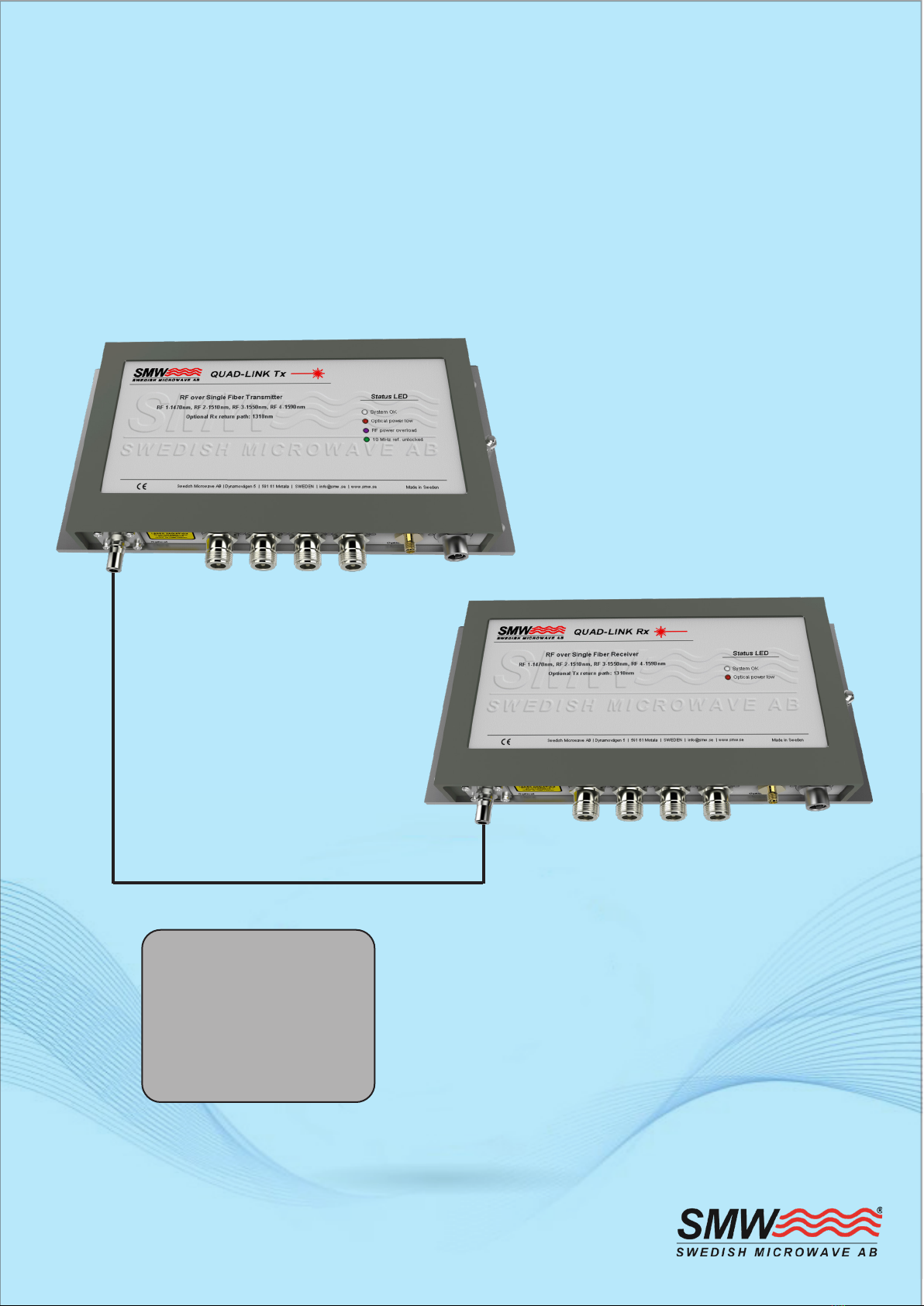
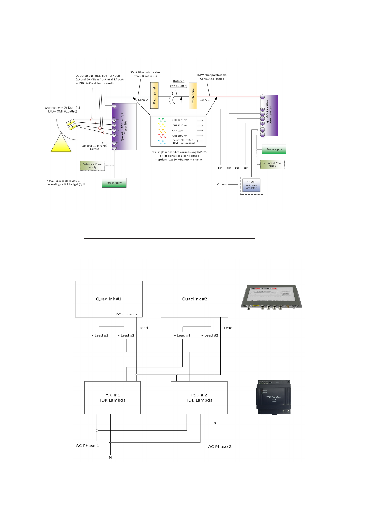
Powering up
Once all desired connections, A through C Fig. 3, have
been made on both Transmitter Tx and Receiver Rx;
• The ber optic cable
• The desired L-band RF connections
• Optional 10 MHz reference
Testing
When all the status indicator LEDs (1 and 2 g. 3) indica-
te normal operation, you can run an RF / L-band testsig-
nal through the system to verify correct operation.
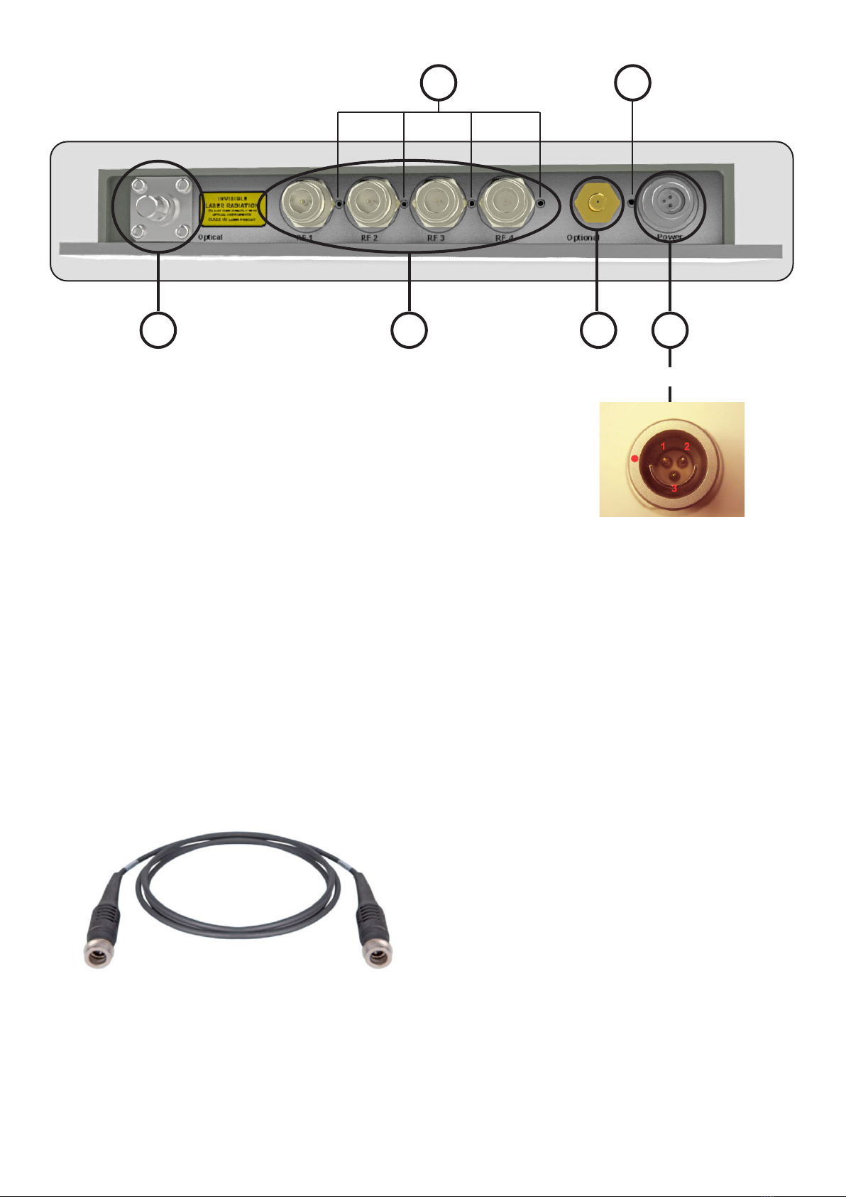
DC power cable
Each unit comes as standard with a 15 m long DC cable
(optionally max 100 m), terminated one end with a
circular IP68 rated Fischer® 103 series plug, which ts
the corresponding connector on each unit’s front panel
(D, g. 3)
The other end is prepared for connection to a DC power
supply which is normally supplied by the user.
The un-terminated end of the cables is labeled corres-
pondingly.
The DC power supply should be sized as indicated above
in this section (D). Application assitance is available,
please contact us. Contact details on back page.
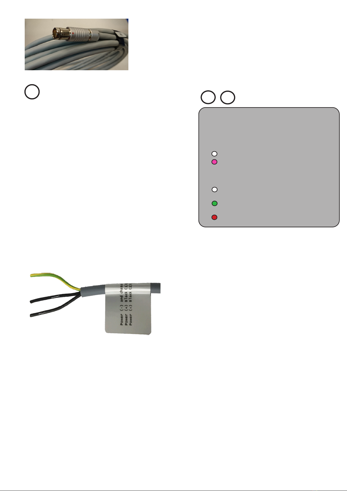
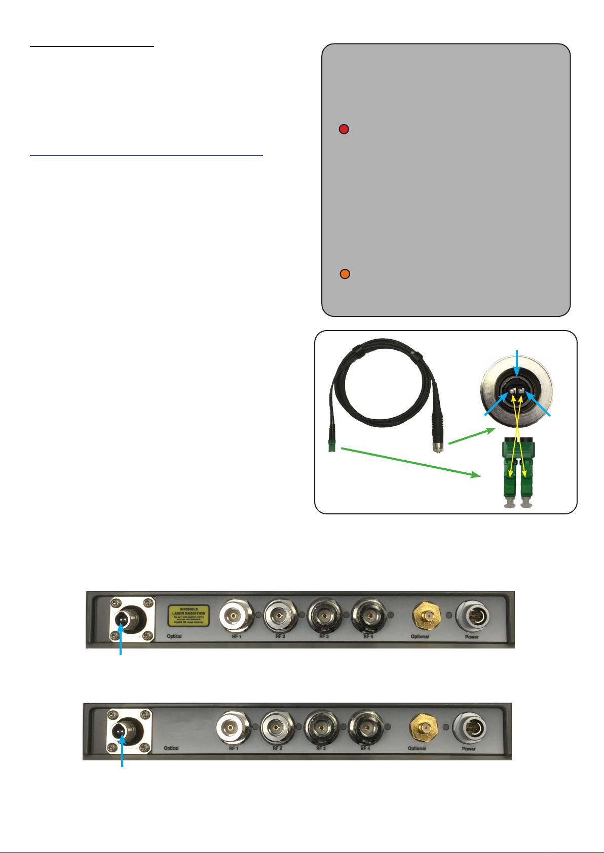
Front panel LED indicators
Normal operation LED indications:
RF / L-band LEDs (1, g. 3):
White: Optical level OK, AGC active
Purple: Transmitter Tx only: Optical level OK,
Fixed Gain mode, AGC not active
Power & 10 MHz ref LED (2, g 3):
White: Power on, Optical level OK, 10 MHz
detected
Green: Power on, Optical level OK, no 10
MHz detected
Red: Power on, Low optical level 10 MHz
12
6
Fig. 8
Service
There are no user serviceable parts inside.
For factory service, contact SMW for an RMA number or
via www.smw.se before returning any material.
Materials returned without an RMA number will be
refused. Standard warranty is 36 months.
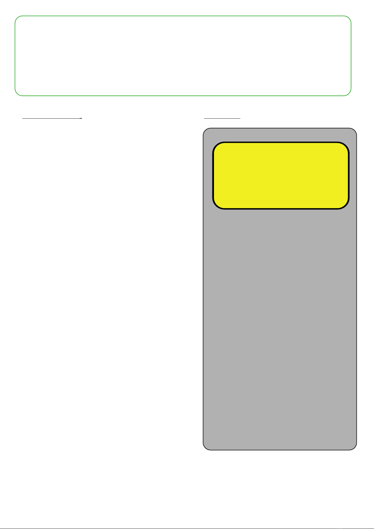
Rx ber input
(right ferrule)
DC Power input
10-28 V DC, min. 15V, 3A recommended if Transmitter Tx
is used with standard type xed LO LNBs as DC power to
the connected LNBs is also fed through from this power
supply. Power Supply must be Galvanically Isolated from
PE Ground. Input is ”Reverse Polarity” and ”Over Voltage
protected”.
Take care when mating the DC connectors with the units,
they are polarized and should never be forced.
Line up the red dot on the cable DC connector (Fig. 8)
with the corresponding dot on the Transmitter Tx or
Receiver Rx DC power input connector (D, Fig. 3). Press
rmly into place intil a click is heard.
The other end of the DC cable is prepared for connection
to a DC power supply and includes 3 leads which can be
utilized for redundant DC power(see sect. 5).
Read carefully about the polarisation of the leads. Leads
marked ”1” and ”2” shall be connected to ”+DC” and
”yellow/green” lead to ”-DC”.
D
Then the units are ready to be powered up with the
correct DC power input on D (Fig. 3) The front panel
status LEDs will light up as follows: