Snap One SunBrite SB-CM-T-M-BL User manual

1
SB-CM-T-M-BL
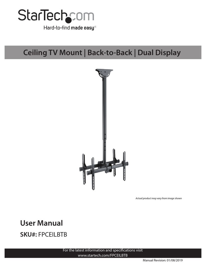
Weatherproof Ceiling Mount for Medium TVs
Install Guide
We recommend this product be installed by a qualified professional. Do not install if you have doubts
regarding the eectiveness or safety of an installation method.
Product Details
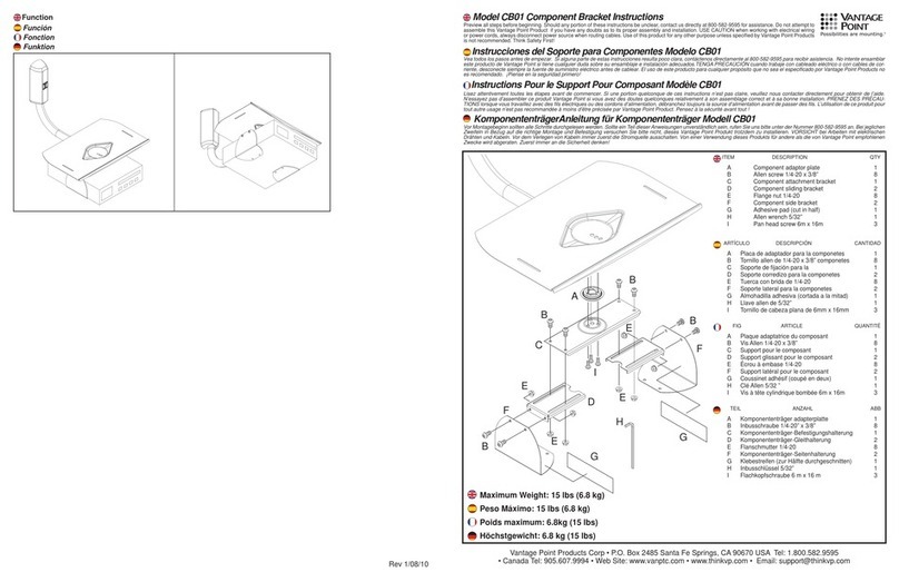
Specifications Box Contents Tools Required
Maximum Load: 36.4 kg (80 lb) Ceiling plate assembly (1) Power drill
Extension: 0.46m (1.5 ft.) Mounting head (1) 3/16" (5 mm) drill bit
Stainless steel hardware Adapter plate (1) 5/16" (8 mm) masonry bit
Pan/swivel range: 360° 0.46m (1.5 ft.) extension pole (1) 1/2" (13 mm) wrench
Tilt range: +0°/-20° Hardware kit (see below) 3/8" socket wrench
Weather-resistant coating 7/16" socket wrench
VESA: 100×100, 200×100, 200×200 Optional: Security Torx bit
sizes: T20, T25, T30, T40
Hardware Kit Contents
Bag 1
Bag 2
Bag 3
Unmarked Bag
(C) M4 × 12 mm
Torx screw (×4)
(D) M4 × 20 mm
Torx screw (×4)
(F) M5 × 30 mm
Torx screw (×4)
(E) M5 × 12 mm
Torx screw (×4)
(B) 19×8.4×2
washer (×10)
(A) ST8 × 63 lag bolt (×6)
(G) M6 × 12 mm
Torx screw (×4) (J) M8 x 16 mm
Torx screw (×4)
(I) M6 × 30 mm
Torx screw (×4)
(H) M6 × 20 mm
Torx screw (×4) (K) M8 x 20 mm
Torx screw (×4)
(M) M5 (16×5.3×1.5 mm)
metal washer (×4)
(N) M6 (18×6.5×1.5 mm)
metal washer (×4)
(L) M4/M5/M6 spacer
12 mm (×4)
(O) M10 × 70 mm screw with lock nut (×1)
(P) M5 x 4 mm set screw (x6)
(Q) M6 × 10 mm
Torx screw (×2)
(R) 15 × 6.5 × 1.5 mm)
metal washer (×2)
Security wrench T20 Security wrench T25 Security wrench T30 Security wrench T40 Hex wrench, 2.5mm

2
Warnings
Do not begin installation until you have thoroughly read and understood these instructions. Failure to comply with these
instructions could result in damage to the product, or serious injury, or death. The manufacturer does not accept responsibility for
incorrect installation.
Do not install if any parts are missing or defective. Do not attempt to replace with unapproved parts or materials or install
without all required parts.
Ensure the ceiling will safely support the combined weight of the mount and your chosen display. TV display should be removed
from mount in situations of high wind exceeding 97 kph (60 mph). Inspect all fasteners and the mounting plate’s attachment to
the ceiling for signs of loosening or damage after any strong wind event, and at least once annually. Tighten any loose fasteners.
If any damage is observed, remove the mount from service.
Installation
Warning: These ceiling mounts are designed for a maximum weight of 80 lbs / 36.4 kg.
Caution: Overtightening can damage the bolts and reduce their holding strength.
Mount the Ceiling Plate
Place the ceiling plate on the mounting surface and mark the
mounting hole locations.
Wood Joist
Drill a minimum of two holes into the joist using a 3/16" drill
bit. Be sure to drill into the center of the joists. Ensure the
plasterboard (if any) is no more than 1/2" thick.
Insert lag screws (A) with washers (B) through the ceiling plate
and tighten.
Concrete Ceiling
Caution: The ceiling must be solid concrete or concrete block. Verify the concrete is at least 1-3/8"
thick and 2000 psi density minimum. Concrete block must meet ASTM C-90 specifications.
Drill in a solid part of the block, 1" minimum from each side. Do not drill into mortar joints.
Caution: Use a standard electric drill on slow setting. Do not use a hammer drill to avoid breaking
out the back of the hole when entering a void or cavity.
Concrete anchors not provided. We recommend an outdoor-
rated 5/16" × 2 1/2" wedge or sleeve anchor for concrete.
Drill four holes into concrete using a 5/16" masonry bit. Insert
hex sleeve anchors, per instructions included with the anchors.
Remove washer and nut from the ends of all four anchors.
Align ceiling plate over the four concrete anchors.
Re-install washers and nuts onto the anchors and tighten until
secure, per instructions included with the anchors.
Wood
Concrete
Example lag layout shown

3
Attach the Extension Pole
Thread the extension pole into the bracket. Screw it in,
ensuring the holes in the pole align with the holes in the
bracket. Slide the safety bolt (O) through the bracket and
pole, and secure it with the safety nut (O). Insert and
tighten the set screw.
Attach the Mount Head
Screw the mount head onto the end of the extension pole
and tighten the set screws.
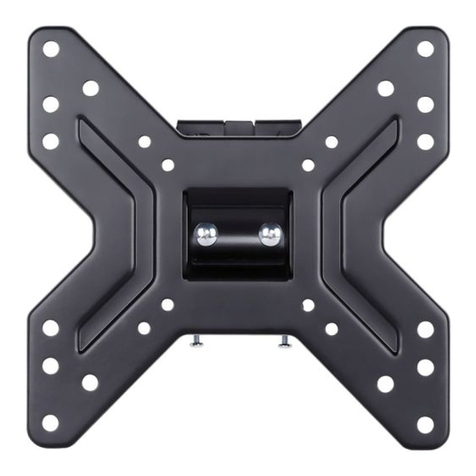
Attach the Adapter Plate to the Display
Attach the adapter plate to the display using M4, M5, M6,
or M8 screws. For displays with a hole pattern in a pocket,
add spacers between the adapter plate and the display.
Attach the Display to the
Ceiling Mount Assembly
Insert the mount head into the hole in the back of the
adapter plate. Lower the display into place.
Secure the adapter plate to the mount head with two
M6×10mm screws and M6 washers.
Using a Phillips screwdriver, tighten the locking screw
located on adapter plate into the threaded hole in the
mount head.

Adjustments
Warning: Completely loosening and/or removing nuts may cause
plate and/or TV to fall.
Tilt Adjustment
Loosen the screws on side of mount head (only enough to allow
controlled adjustment), then adjust the tilt forward or backward.
Tighten the screws to ensure that the tilt angle is locked.
4
Technical Support
For technical support, please call 866-357-8688 or visit https://www.sunbritetv.com/support/services/contact-support, fill out the
support request form, and our support team will respond via email.
Visit tech.control4.com/technician for discussions, instructional videos, news, and more.
Warranty and Legal Notices
Find details of the product’s Limited Warranty and other resources such as regulatory notices and patent and safety information,
at snapone.com/legal or request a paper copy from Customer Service at 866.424.4489.
Copyright ©2022, Snap One, LLC. All rights reserved. Snap One and its respective logos are registered trademarks or
trademarks of Snap One, LLC, in the United States and/or other countries. Control4, SunBriteDS, and SunBriteTV are also
registered trademarks or trademarks of Snap One, LLC. Other names and brands may be claimed as the property of their
respective owners. Snap One makes no claim that the information contained herein covers all installation scenarios and contin-
gencies, or product use risks. Information within this specification subject to change without notice.
220331-1650
Part # 200-SB-CM-T-M-BL-001-C
