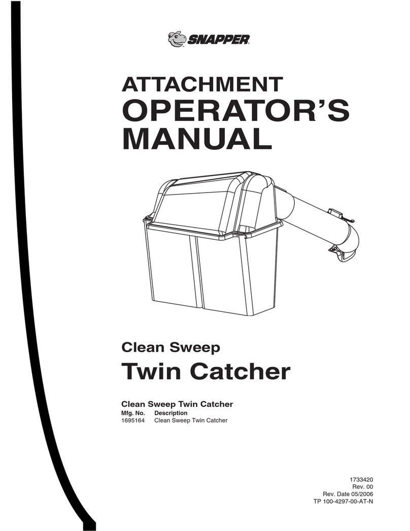
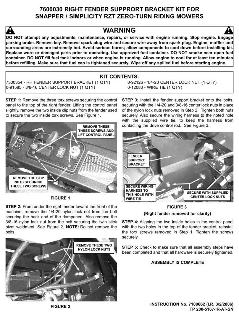
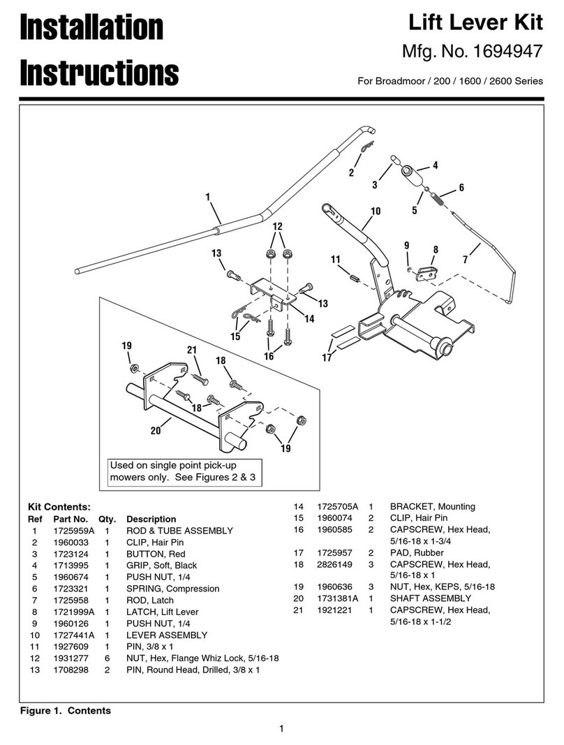
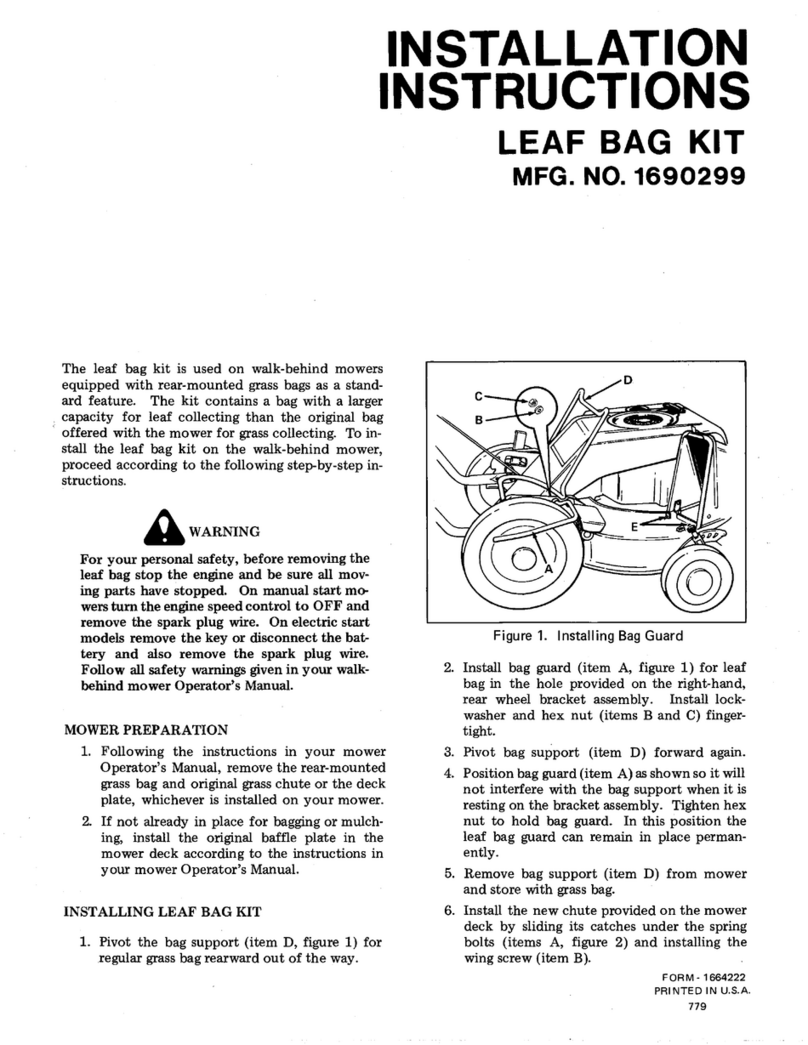
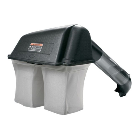
Snapper 6-3172 User manual

Safety Instructions, Installation & Operator’s Manual For
#6-3172 SINGLE BAG GRASS CATCHER KIT
FOR 38” YARD CRUISERS SERIES 2
MODEL YZ145382BVE
COPYRIGHT © 2000
SNAPPER INC.
ALL RIGHTS RESERVED
MANUAL No. 7-3955 (REV. 1, 12/08/00)
IMPORTANT !
THIS KIT NOT INTENDED FOR
USE ON ANY SERIES OF HZ/HZS
YARD CRUISERS.

2
IMPORTANT SAFETY INSTRUCTIONS
WARNING
All safety instructions and operating instructions in the manuals provided with the Snapper Yard Cruiser and
this Grass Catcher attachment must be followed. Read, understand, and follow ALL instructions and warnings
in the Operator’s Manual provided with the machine, with this attachment, and ALL instructions and warnings
on the machine, engine and attachment. Failure to comply with ALL instructions and warnings can result in
damage, serious injury or death to the operator or other persons.
1) DO NOT allow children or others in the yard
when the machine is operated (even with the
blades off).
2) DO NOT allow children or others to ride on the
machine or attachment (even with the blades
off).
3) DO NOT allow children to operate the machine.
4) DO NOT operate blades in reverse. STOP
blades. LOOK and SEE behind and down for
children, pets, and hazards before and while
backing.
5) FRONT WEIGHT must be installed before
operating machine with grass catcher.
6) DO NOT operate machine on slopes exceeding
10 degrees (18% grade) when equipped with
grass catcher.
7) Exercise EXTREME CAUTION on all slopes.
Turn blades off when traveling uphill. Use a
slow speed and avoid sudden or sharp turns.
8) DO NOT operate machine across face of slopes.
Operate up and down. Practice on slopes with
blades off.
9) AVOID uphill starts. If machine stops going up
hill or tires lose traction, turn blades OFF and
back slowly down the slope.
10) GRASS CATCHER COMPONENTS are subject to
deterioration during normal use. Inspect all
components frequently for signs of wear or
deterioration. Replace worn or damaged
components immediately.
11) DO NOT leave machine with engine running.
STOP engine, STOP blades, SET brake, and
REMOVE key before leaving operator’s position
for any reason.
12) DO NOT attempt to remove or unclog the grass
catcher with engine or blades running. Stop
engine and blades and make sure all rotating
components have come to a complete stop
before removing any catcher component or
attempting to unclog catcher or deck.
13) DO NOT operate machine without entire Grass
Catcher or Guards in place.
14) DO NOT operate machine without grass bag in
place and properly latched.

3
TABLE OF CONTENTS
IMPORTANT SAFETY INSTRUCTIONS ..............................................................2
TABLE OF CONTENTS........................................................................................3
SECTION 1 - ASSEMBLY INSTRUCTIONS .................................................... 4-8
Introduction.............................................................................................................................. 4
Bumper Bracket Installation................................................................................................... 4
Muffler Heat Shield Installation.............................................................................................. 4
Front Weight Plate Installation............................................................................................... 5
Mounting Strap Installation .................................................................................................... 5
Deck Adapter Installation .................................................................................................... 5-6
Dust Skirt & Frame Assembly Installation ......................................................................... 6-7
Grass Bag Assembly............................................................................................................... 7
Grass Bag Installation ............................................................................................................ 7
Blade & Air Lift Installation ................................................................................................. 7-8
Deck Baffle Installation........................................................................................................... 8
Grass Tube Installation........................................................................................................... 8
SECTION 2 – OPERATION & MAINTENANCE ............................................. 9-12
Introduction.............................................................................................................................. 9
Grass Catcher Operation........................................................................................................ 9
Emptying Grass Catcher ........................................................................................................ 9
If The Grass Catcher Becomes Clogged............................................................................... 9
Grass Catcher Maintenance ................................................................................................... 9
Before Each Use ...................................................................................................................... 9
Single Bag Assembly Components................................................................................ 10-13

4
SECTION 1 – ASSEMBLY INSTRUCTIONS
INTRODUCTION: The #6-3157 Single Bag Grass Catcher Kit fits Snapper Yard Cruiser YZ145382BVE, Series 2,
models only. This Kit is not intended for use on Series 1 YZ models or any Series of HZ and HZS Yard Cruisers.
Use the following instructions to assemble the grass catcher components and prepare your machine for
collecting grass clippings and leaves. Follow and complete each step carefully.
WARNING
DO NOT attempt any adjustments, maintenance or
service with the engine running. STOP engine.
STOP blade. Engage parking brake. Remove key.
Remove spark plug wire from spark plug and
secure wire away from spark plug. Engine and
components are HOT. Avoid serious burns, allow
all parts to cool before working on machine.
STEP 1
BUMPER BRACKET
A. Remove the top right bumper bolt and loosen top
right frame bolt. See Figure 1.1.
B. Slide slot in bumper bracket under head of right
frame bolt. Push bracket firmly against rear bumper
and reinstall bumper bolt and tighten both bolts
securely. See Figure 1.2.
FIGURE 1.1
FIGURE 1.2
STEP 2
MUFFLER HEAT SHIELD INSTALLATION
IMPORTANT! To avoid damage to grass catcher
components, the muffler heat shield must be installed
before operating machine.
A. Loosen bolt on top of muffler heat shield. See
Figure 1.3.
B. Place muffler heat shield under existing heat shield
on muffler and slide slot forward onto bolt.
C. Make sure that the slot is completely forward and
tighten bolt securely.
FIGURE 1.3
LOOSEN
ONLY
REMOVE
BUMPER
BOLT
LOOSEN
ONLY
HEAT SHIELD. SLIDE UNDE
R
EXISTING HEAT SHIELD.
SLIDE BUMPE
R
BRACKET UNDER BOLT

5
SECTION 1 – ASSEMBLY INSTRUCTIONS
WARNING
Front weight plates must be installed before
operating machine with grass catcher.
STEP 3
FRONT WEIGHT PLATE INSTALLATION
A. Remove (4) knobs attaching floor pan to front
frame. Remove floor pan.
B. Attach (4) weight plates to front frame using (1) 3/8-
16 x 2” hex bolt, (2) 3/8” flat washers, (1) 3/8” split
lock washer and (1) 3/8-16 hex nut. Place four
weight plates on front bumper and align holes.
Insert bolt with flat washer from top. Secure weights
in place with flat washer, split lock washer and hex
nut. Tighten securely. See Figure 1.4.
C. Do not install the floor pan at this time
FIGURE 1.4
WARNING
DO NOT operate machine without entire grass
catcher or guards in place.
STEP 4
MOUNTING STRAP INSTALLATION
A. Install mounting straps to the grass tube and deck
adapter using hardware supplied in kit. See Page
12 & 13 for parts illustration.
STEP 5
DECK ADAPTER INSTALLATION
A. Remove the carriage bolt and lock nut, which
secure the pivot rod to the deck. See Figure 1.5
B. Slowly lift the loose end of the pivot rod to release
the tension on the deflector spring.
C. Remove the deflector, pivot rod, spring and mounting
rod from the deck. (NOTE: Save all parts for future
use when not bagging grass).
D. Install screw, washer and “T” nut from kit. Tighten
securely. Mount adapter to side of deck. See Figure
1.6.
WARNING
The lower end of the spring is held under tension by
the spring slot and can cause injury to the hand or
fingers when it is released.
FIGURE 1.5
FIGURE 1.6
(Continued On Next Page)
3/8-16 X 2” HEX BOLT
& FLAT WASHER
(4) WEIGHT
PLATES
DEFLECTO
R
SPRING
SPRING
SLOT
REMOVE
CARRIAGE
BOLT
38”
DECK
REMOVE
NUT
WASHE
R
P.N. 9-0188

6
SECTION 1 – ASSEMBLY INSTRUCTIONS
STEP 5
DECK ADAPTER INSTALLATION
E. Secure the front of the adapter to the gage wheel
mounting bracket with the mounting strap. Secure
side of adapter with mounting strap hooked into deck
flange. See Figure 1.7.
FIGURE 1.7
FIGURE 1.7
STEP 6
DUST SKIRT & FRAME ASSEMBLY INSTALLATION
A. Attach dust skirt to catcher frame with the heat
patch located towards the muffler side of the
machine. Locate the two oblong holes at the top
front of the skirt. Carefully remove the material
filling the holes. A knife or scissors may be required
B. Lay dust skirt flat on floor with heat patch to the
right and oblong holes away from you. Position
frame over skirt and align frame bumper mounting
brackets with oblong holes in skirt. Pull skirt up the
brackets, wrap edge of skirt around outside of
frame tube and position the 5 eyelet holes down
over the frame studs. See Figure 1.8.
FIGURE 1.8
C. Position catcher frame over rear bumper and
secure in place with (2) 5/16” diameter clevis pins
and (2) hairpins. NOTE: Skirt must be behind
bumper, away from engine. See Figure 1.9.
FIGURE 1.9
D. Attach catcher latch to frame assembly using (1)
#10-32 x 1 11/16” screw and (1) #10-32 Nyloc lock
nut. Tighten nut so that the latch is snug but still
able to rotate. See Figure 1.10.
FIGURE 1.10
(Continued on Next Page)
DUST
SKIIRT
(5) FRAME STUDS
2
13
4
5
BUMPE
R
MOUNTING
BRACKETS
HEAT
PATCH
5/16”
CLEVIS PINS
& HAIRPINS
CATCHE
R
LATCH
(1) #10-32 x 1-11/16”
SCREW & NYLOC
LOCK NUT
ADAPTER
ADAPTE
R
MOUNTING
STRAP
ATTACH HOOK TO
DECK FLANGE
ATTACH
HOOK
TO GAGE WHEEL
MOUNTING BRACKET

7
SECTION 1 – ASSEMBLY INSTRUCTIONS
STEP 6
DUST SKIRT & FRAME ASSEMBLY INSTALLATION
A. Align (5) holes in the plastic catcher top with the
studs on the frame assembly. Secure in place using
(5) special nuts (2-9840). See Figure 1.11.
FIGURE 1.11
STEP 7
GRASS BAG ASSEMBLY
A. Using a hammer, tap the tubular rod connector onto
one of the open ends of the catcher support rod. Tap
until approximately one half of the length is over the
rod. See Figure 1.12.
FIGURE 1.12
B. Insert the end of the rod without the connector into
the top loop of the grass bag. Work the loop of the
bag completely around the rod until the loop opening
is over the rod opening. See Figure 1.13.
C. Position open end of rod into connector. Tap on rod
until fully seated into connector.
STEP 8
GRASS BAG INSTALLATION
IMPORTANT! Grass bag must be installed correctly to
prevent excess blowout on engine and towards operator.
Do Not operate machine without bag in place and
securely latched.
A. Position bag with open mesh side of the material
facing towards the rear away from the engine. Align
grass bag with the two hangers on the frame
assembly and slide fully into place.
B. Rotate latch down to secure bag into place. See
Figure 1.14.
FIGURE 1.13
FIGURE 1.14
WARNING
Wear heavy leather gloves when handling or working
around cutting blades. Blades are extremely sharp and
can cause severe injury. DO NOT use a cutting blade
that shows signs of excessive wear or damage.
STEP 9:
BLADE AND AIR LIFT INSTALLATION
IMPORTANT: This kit contains bolt on type air lifts and
high lift type blades. Yard Cruisers with engines that
produce 14 horse power or more can use the high lift
blades or bolt on type air lifts. Yard Cruisers with
engines that produce less than 14 horse power must use
bolt on type air lifts only. DO NOT use the high lift type
blades on Yard Cruisers with engines that produce less
than 14 horse power.
HIGH LIFT BLADE INSTALLATION
A. Note: High lift blades are only used on 14
horsepower 38" mower decks (for 13 horsepower,
go to next step). Remove existing blades from
mower. NOTE: Save old blades for later use when
not bagging grass. Using existing hardware, install
high lift type blades. Torque blade retaining bolts to
80 to 90 ft. lbs. See Figure 1.15.
(Continued on Next page)
SUPPORT
ROD
TUBULA
R
CONNECTOR
LATCH
ROTATE
DOWN
RODS FULLY SEATED
IN CONNECTOR
(5) SPECIAL
NUT (2-9840)
1
2
34
5

8
SECTION 1 – ASSEMBLY INSTRUCTIONS
FIGURE 1.15
AIR LIFT INSTALLATION
(Engines that produce less than 14 horse power.)
A. Remove existing blades from mower. Install air lifts
to the tips of blades using nuts and bolts supplied
with kit. Be certain to install lifts to both ends of both
blades. Torque nuts and bolts to 20 to 30 ft. lbs. on
air lifts. Using existing hardware, reinstall blades to
mower deck. Torque blade retaining bolts to 80 to
90 ft. lbs. See Figure 1.16.
FIGURE 1.16
STEP 10
BAFFLE INSTALLATION
NOTE: The baffle installation may not be required for all
mowing applications. It is recommended that the baffle be
installed if the following conditions exist; if operator is
bagging grass in extremely dry conditions, is experiencing
excessive debris blow out from the front of deck or is
bagging leaves.
A. Mounting holes will have to be drilled to mount baffle
to the front of deck. Remove the two nuts that secure
the left wheel bracket.
Place the baffle onto bracket bolts and reinstall nuts onto
bolts to hold baffle in position. Do not completely tighten at
this time. NOTE: If there are two existing holes in deck it
will not be necessary to drill new holes. Make sure bottom
of deck is parallel to bottom of baffle and support left end
of baffle with c-clamp or similar tool. Use both holes in
baffle as a reference; mark the deck for drilling. Drill holes
in deck using an 11/32 drill. Insert the 5/16 x 3/4 hex cap
screws from underneath deck to the outside, through
baffle, and secure with 11/32 washers and 5/16 hex lock
nuts. Tighten all nuts securely. See Figure 1.17.
FIGURE 1.17
STEP 11
TUBE TO COVER INSTALLATION
A. Slide upper end of grass tube into opening of cover
assembly. See Figure 1.18.
B. Slide lower end of grass tube over adapter. Hook tube
strap (on grass tube) onto latch that is anchored to
adapter. See Figure 1.18.
FIGURE 1.18
9-1318
BAFFLE
4-4726
9-1575
9-0188
3-6547
BLADE
(2-REQUIRED)
CONE
WASHER
MOUNTING NUT
AIR LIFT
LOC
K
WASHER
HEX
NUT
BLADE
SCREW
#6-0480 AIR LIFT KIT.
38” DECK - 2 KITS
REQUIRED
COVER/FRAME
ASSEMBLY
GRASS TUBE
SECURE TUBE
STRAP (HOOK) TO
ADAPTER LATCH
(“T” NUT)
ADAPTER
SLIDE GRASS TUBE INTO
COVER/FRAME ASSEMBLY
FIRST, THEN CONNECT
TUBE TO THE ADAPTER

9
SECTION 2 – OPERATION & MAINTENANCE
INTRODUCTION
Follow operation and maintenance instructions in
the Operator’s Manual provided with the Snapper
Yard Cruiser Riding Mower.
2.1 GRASS CATCHER OPERATION
A. Select desired cutting height. Choose a setting that
will not attempt to cut off too much at once,
overloading the machine.
B. After starting engine and allowing a brief warm up
period, move engine speed control to highest
setting.
C. Drive machine to cutting area. Engage blades.
D. Select a slow forward ground speed until familiar
with conditions. Do not select a speed that is too
fast, causing the machine to become overloaded.
E. The weight of the grass catcher and contents will
affect the stability and handling of the machine.
Avoid sudden starts and sharp turns. Reduce
speed on slopes, and DO NOT operate machine on
slopes exceeding 10 degrees (18% grade). Operate
machine up and down slopes. DO NOT operate
machine across the face of slopes. Turn blades off
when traveling up slope.
F. Empty grass catcher often to minimize effect on
stability and handling. Over filling the catcher will
reduce performance and cause clogging of the
tube, adapter and deck.
G. Do not operate the machine without the bag
installed. The entire grass catcher must be installed
and the bag properly latched in position.
2.2 EMPTYING GRASS CATCHER
A. Empty Grass Catcher often to avoid overfilling.
Overfilling reduces performance and causes
clogging of tube, adapter and deck.
B. Turn blades off. Drive machine to location the
clippings are to be dumped. DO NOT operate
blades in reverse. If you must back machine to
dump clippings in desired location, LOOK and SEE
behind and down for children, pets and hazards
before and while backing.
C. Bring joystick motion control to neutral. Engage
park brake. Stop engine. Remove key.
D. Unlatch bag. Grip bag frame firmly and slid out of
frame assembly.
E. Place bag on ground and roll over, dumping
contents.
F. Shake bag or tap sides to remove debris from bag
material. Bag should be kept clean to maintain peak
performance.
G. Install grass bag, making sure that the open mesh
side faces towards the rear (away from the engine).
H. Latch securely.
G. Restart engine and drive machine to cutting area.
Set engine speed to highest setting, engage blades
and resume operation.
WARNING
DO NOT attempt to remove any clogs from deck,
adapter, or tube with engine or blade running.
STOP engine. STOP blade. Engage parking brake.
Remove key. Make sure blade and all rotating
components have come to a complete stop before
removing or unclogging any catcher component.
2.3 IF THE GRASS CATCHER BECOMES CLOGGED
The grass catcher may become plugged if the
conditions are too severe, the catcher is overfilled, or
the machine is used improperly. If plugging does occur,
attempt the following:
1. Empty catcher more often.
2. Clean debris buildup from bag material.
3. Ground speed too fast – cut at slower speed.
4. Removing too much grass – raise cutting height,
cut partial width, and cut lawn more frequently.
5. Grass is too wet from rain or dew – allow grass to
dry.
6. Blades are dull or worn – inspect blades and
replace as necessary. Use only genuine SNAPPER
replacement blades.
7. Mower equipped with incorrect blade. Catcher
operation requires high lift blade. Contact your local
SNAPPER dealer for assistance in choosing the
correct blade for your application.
8. Deck, adapter, or tube has clipping build up – clean
all clippings from all internal surfaces.
2.4 GRASS CATCHER MAINTENANCE
Grass Catcher components are subject to wear and
deterioration during normal usage. Inspect all
components frequently for signs of wear and
deterioration. Replace worn or damaged components
immediately.
BEFORE EACH USE
A. Inspect all Catcher components. Replace all worn
or damaged parts.
B. Clean grass build up from deck, adapter, grass
tube, cover and bag. For peak performance the bag
material must be clean.
C. Inspect blade for wear or damage. Replace as
needed.
D. Perform pre-start check list and maintenance as
instructed in the SNAPPER Yard Cruiser Riding
Mower Operator’s Manual and Engine Owner’s
Manual included with the machine.
10
SINGLE BAG GRASS CATCHER ILLUSTRATION
(Continued on Page 12)
25
24
5
26
10
15
12
9
11
4
8
6
7
2
3
1

11
SINGLE BAG GRASS CATCHER PARTS LIST
(Continued on Page 13)
ITEM PART NO. DESCRIPTION
1 5-7983 TOP, Container
2 7-1679 SKIRT, Dust
3 2-9840 WASHER, Faceted (5)
4 4-6651 FRAME, Grass Bag (Weldment)
5 2-9841 CLEVIS PIN, 5/16 x 1-11/16” (2)
6 3-1725 LATCH, Grass Catcher
7 9-0532 SCREW, 10-32 x 1-11/16” Hex Cap
8 9-0376 NUT, 10-32 Hex Lock w/Nylon Insert
9 3-7758 ROD, Bag
10 9-1503 PIN, 3/32 x 1-1/2” Hair (2)
11 1-2556 CONNECTOR, 1/2 x 3” Rod
12 1-9251 BAG, Single Zipperless
13 4-6615 TUBE, Grass
14 5-8910 HEAT SHIELD (see Figure 1.3 on Page 4)
15 2-3797 PAD, Bumper Mount
16 3-6404 NUT, #10-24 x Weld (3)
17 3-6433 STRAP, Mounting Bag Adapter/Tube (3)
18 3-6422 WASHER, 3/16 Flat (3)
19 3-6543 NUT, 5/16-18 “T”
20 9-1296 WASHER, 11/32” Flat (2)
21 4-2716 BRACKET, Bumper Reinforcement (see Fig. 1.1 on Page 4)
22 5-8909 BALLAST (4) (see Figure 1.4 on Page 5)
23 9-1552 WASHER, 7/32” Flat Lock (3)
24 9-0184 NUT, 5/16-18 Hex Center Lock (2)
25 9-0188 WASHER, 5/16” Flat (2)
26 9-0577 BOLT, 5/16-18 x 1-1/2” Round Head Square Neck, Grade 5 (2)
27 9-0118 WASHER, 3/8” Split Lock
28 9-0122 WASHER, 3/8” Flat (2)
29 9-0130 NUT, 3/8-16 Hex
30 3-6415 SCREW, #10-24 x 5/8” Pan Head (3)
31 9-1833 SCREW, 5/16-18 x 5/8” Pan Head
32 5-7810 ADAPTER, Bag (Includes 4-6720 Decal)
33 9-0588 SCREW, 3/8-16 x 2” Hex Head Cap, Grade 5

12
SINGLE BAG GRASS CATCHER ILLUSTRATION
(Continued From Page 10)
31
18
17
23
32
23
30
20
19
18
13
23
17
16
28
22
33
14
21
27
29
17
18
16
16
30
30

13
SINGLE BAG GRASS CATCHER PARTS LIST
(Continued From Page 11)
ITEM PART NO. DESCRIPTION
1 5-7983 TOP, Container
2 7-1679 SKIRT, Dust
3 2-9840 WASHER, Faceted (5)
4 4-6651 FRAME, Grass Bag (Weldment)
5 2-9841 CLEVIS PIN, 5/16 x 1-11/16” (2)
6 3-1725 LATCH, Grass Catcher
7 9-0532 SCREW, 10-32 x 1-11/16” Hex Cap
8 9-0376 NUT, 10-32 Hex Lock w/Nylon Insert
9 3-7758 ROD, Bag
10 9-1503 PIN, 3/32 x 1-1/2” Hair (2)
11 1-2556 CONNECTOR, 1/2 x 3” Rod
12 1-9251 BAG, Single Zipperless
13 4-6615 TUBE, Grass
14 5-8910 HEAT SHIELD (see Figure 1.3 on Page 4)
15 2-3797 PAD, Bumper Mount
16 3-6404 NUT, #10-24 x Weld (3)
17 3-6433 STRAP, Mounting Bag Adapter/Tube (3)
18 3-6422 WASHER, 3/16 Flat (3)
19 3-6543 NUT, 5/16-18 “T”
20 9-1296 WASHER, 11/32” Flat (2)
21 4-2716 BRACKET, Bumper Reinforcement (see Fig. 1.1 on Page 4)
22 5-8909 BALLAST (4) (see Figure 1.4 on Page 5)
23 9-1552 WASHER, 7/32” Flat Lock (3)
24 9-0184 NUT, 5/16-18 Hex Center Lock (2)
25 9-0188 WASHER, 5/16” Flat (2)
26 9-0577 BOLT, 5/16-18 x 1-1/2” Round Head Square Neck, Grade 5 (2)
27 9-0118 WASHER, 3/8” Split Lock
28 9-0122 WASHER, 3/8” Flat (2)
29 9-0130 NUT, 3/8-16 Hex
30 3-6415 SCREW, #10-24 x 5/8” Pan Head (3)
31 9-1833 SCREW, 5/16-18 x 5/8” Pan Head
32 5-7810 ADAPTER, Bag (Includes 4-6720 Decal)
33 9-0588 SCREW, 3/8-16 x 2” Hex Head Cap, Grade 5

14
NOTES

15
NOTES

16
Safety Instructions, Installation & Operator’s Manual For
#6-3172 SINGLE BAG GRASS CATCHER KIT
FOR 38” YARD CRUISERS SERIES 2
MODEL YZ145382BVE
COPYRIGHT © 2000
SNAPPER INC.
ALL RIGHTS RESERVED
MANUAL No. 7-3955 (REV. 1, 12/08/00)
Table of contents
Other Snapper Lawn Mower Accessories manuals

Snapper
Snapper 6-1238 User manual

Snapper
Snapper 500Z - 26 Manual

Snapper
Snapper 1690170 User manual

Snapper
Snapper EC13V User manual

Snapper
Snapper 1695195 User manual

Snapper
Snapper PRO Parts list manual

Snapper
Snapper 0-50576 User manual

Snapper
Snapper 6-0935 User manual

Snapper
Snapper 6-1249 User manual

Snapper
Snapper 1690116 User manual

Snapper
Snapper 7600036 User manual

Snapper
Snapper 318 User manual

Snapper
Snapper FAST-Vac Manual

Snapper
Snapper 7600053 User manual

Snapper
Snapper 1692714 User manual

Snapper
Snapper 1690047 User manual

Snapper
Snapper 1690045 User manual

Snapper
Snapper 6-0431 User manual

Snapper
Snapper 1694498 User manual

Snapper
Snapper 1694955 User manual