Snapper PRO Parts list manual

1
SET-UP INSTRUCTION & PRE-OPERATION CHECKLIST
SNAPPER PRO 21" STEEL DECK COMMERCIAL WALK BEHIND MOWERS
INTRODUCTION: The SNAPPER PRO Walk Behind Mowers are shipped almost fully assembled and require
minimal set-up. Complete each of the following steps carefully. Review and complete each item as instructed
on the Pre-Operation checklist.
WARNING – DO NOT ATTEMPT TO START OR
OPERATE THIS UNIT UNTIL ALL ASSEMBLY
STEPS HAVE BEEN COMPLETED. SERIOUS
INJURY OR EQUIPMENT DAMAGE MAY RESULT.
HANDLE ASSEMBLY
STEP 1: Remove mower from shipping carton. These
mowers are manufactured with (4) 5/16-18 hex head
cap screws, and (4) 5/16 bolt retainers that secure the
upper, middle handles and lower handle brackets
together for packaging purposes. This hardware will
have to be removed and discarded. See Figure 1.
REMOVE EXISTING HARDWARE
FIGURE 1
STEP 2: New hardware can be found in hardware bag.
Attach middle handle to lower handle brackets using
5/16-18 x 1-1/2” curved head bolts, installed from the
inside of handles as shown, and secure with 5/16
internal tooth lock washers and hex nuts. Do not tighten
at this time. See Figure 2.
STEP 3: Attach the upper handle assembly to the middle
handle using 5/16-18 x 1-1/2” curved head bolts,
installed from the inside of handles as shown, and
secure with 5/16 internal tooth lock washers and hex
nuts. Do Not tighten at this time. See Figure 3.
FIGURE 2
FIGURE 3
FIGURE 4
INSTRUCTION No. 7103223 (Rev. ‘-’, 3/18/2009)
UPPER
HANDLE
MIDDLE
HANDLE
5/16 BOLT
RETAINER
5/16 BOLT
RETAINER
5/16 HEX HEAD CAP
SCREWS
5/16 HEX
HEAD CAP
SCREWS
MIDDLE
HANDLE
5/16 BOLT
RETAINER
LOWER
HANDLES
MIDDLE
HANDLE
LOWER
HANDLE
(Left Side)
5/16 X 1-1/2”
CURVED
HEAD BOLT
5/16 HEX
NUTS
5/16 LOCK
WASHERS
UPPER
HANDLE
MIDDLE
HANDLE
INTERNAL
TOOTH LOCK
WASHER
5/16 X 1-1/2”
CURVED
HEAD BOLTS
HEX NUT
LOWER HANDLE
BRACKET
LOOSEN
THREE NUTS
Not for
Reproduction

2
STEP 4: To adjust handle height loosen bolts on both
lower handle brackets. See Figure 4. Move handles up
or down for desired height. See Figure 5. Tighten all
bolts and nuts on all handles and brackets.
FIGURE 5
STEP 5: Install handle braces between lower handles
and drive disc bracket on back of mower deck. See
Figure 6. Align top hole of each brace with slotted hole
in top portion of each lower handle, and secure with
5/16-18 x 3/4” hex washer head bolt and flange nut.
Align hole in bottom of both braces with hole in rear of
drive disc bracket, securing with same hardware as
above. Tighten securely. NOTE: Attach bottom of both
braces to outside of drive disc bracket.
FIGURE 6
STEP 6: Squeezing brake control against upper handle,
grasp engine recoil and pull firmly past recoil rope guide
on right side of upper handle. Hook recoil rope into eye
of rope guide. See Figure 7.
FIGURE 7
STEP 7:
1. Install Operator console onto upper handle
section with four 1/4-20 x 1/2” torx screws. See
Figure 8.
2. Firmly press Engine speed handle onto right
lever as shown.
3. Slip ground speed handle onto left lever as
shown, securing with one 8-32 x 1/2” round head
machine screw and hex nut. (Be sure nut sets
into hexagonal depression in side of handle.)
FIGURE 8
MOVE
UPPER
HANDLE UP
OR DOWN
FOR PROPER
HEIGHT
LOWER
HANDLE
DRIVE DISC
BRACKET
HANDLE
BRACES
ENGINE SPEED
LEVER HANDLE
GROUND SPEED
LEVER HANDLE
OPERATOR
CONSOLE
SQUEEZE BRAKE
CONTROL
PULL RECOIL
ROPE AND HOOK
INTO ROPE GUIDE
Not for
Reproduction

3
DRIVE ASSEMBLY
STEP 1:
1. Remove driven disc spring from driven disc
assembly as shown. See Figure 9.
FIGURE 9
2. Manually adjust driven disc to position shown in
Figure 10.
FIGURE 10
3. Slide Ground speed control lever fully forward.
See Figure 11.
4. Install threaded end of Ground speed control
rod, fitted with one 1/4-28 jam nut, into ball joint
on end of speed control pivot arm. See Figure
12. IMPORTANT: Do not move pivot arm.
5. Thread rod in until upper end of rod aligns with
hole in bottom of ground speed control lever.
See Figure 11. Insert upper end of rod into hole,
and secure with 5/16” flat washer and hair pin.
6. Slide Ground speed lever back, then fully
forward again. Check driven disc position. If
needed, repeat #5 above until 1/8” in Figure 10
is maintained, then tighten jam nut securely
against ball joint.
7. Replace driven disc spring to driven disc
assembly. See Figure 9.
FIGURE 11
(Operator Console and Ground speed handle
removed for clarity)
FIGURE 12
GROUND SPEED
CONTROL ROD
WASHER &
HAIR PIN
(HIDDEN)
GROUND SPEED
CONTROL ROD
BALL JOINT
PIVOT ARM
JAM NUT
GROUND SPEED
CONTROL LEVER
(FULLY FORWARD)
1/8” MEASUREMENT
TO OUTSIDE EDGE
OF DRIVE DISC
DRIVE
DISC
SLIDE DRIVEN DISC
ASSEMBLY TOWARD
OUTSIDE EDGE
TRANSFER
ROD OUTSIDE
EDGE
DRIVEN DISC
ASSEMBLY
DRIVEN
DISC
SPRING
TRANSFER
ROD
DRIVE
DISC
Not for
Reproduction

4
STEP 2:
IMPORTANT: Clutch cable adjustments are made to the
machine at the factory. The following adjustments are
provided for reference only. Complete all items on the
Pre-Operation Checklist as instructed.
Check the clearance between the clutch cable and
clutch spring. NOTE: Clearance between spring and
cable is very important. Excessive clearance will cause
drive system NOT to operate when wheel drive control
handle is depressed. No clearance at all will cause
mower to continue to propel itself when wheel drive
control handle is released to stop mower movement.
Slide vinyl spring cover (located at the end of clutch
cable) up clutch cable to gain access to the end of
spring and cable loop. With wheel drive control handle
released, clearance between spring hook and cable
loop should be 1/16” to 1/8”. If clearance is more or less
than specified, unhook spring from clutch cable eye,
then adjust by turning inner spring in an opposite
direction than the outer spring. Rehook spring to clutch
cable eye. Slide vinyl cover over the spring when
correct clearance is reached. See Figure 13.
FIGURE 13
DISCHARGE ASSEMBLY
NOTE: Discharge assemblies vary by model. Some
assembly steps shown may not apply to your model.
GRASS BAG
STEP 1: Install the grass bag adapter and secure to the
side and top of the deck with the two nuts provided with
the machine. Slot in front edge of adapter must be under
nut located on top of deck. See Figure 14.
FIGURE 14
STEP 2: Route recoil rope around rope guide pulley on
top of bag adapter. See Figure 15. NOTE: Pulling
blade control up against upper handle will free up recoil
slack.
FIGURE 15
SPRINGS
INNER
SPRING
OUTER
SPRING
1/16” - 1/8”
CLEARANCE
VINYL SPRING
COVER
CLUTCH CABLE
CABLE
CLUTCH
CABLE EYE
SECURE ADAPTER
TO DECK WITH NUTS
SECURE
WITH NUTS
ADAPTER
ROPE GUIDE
PULLEY
RECOIL
ROPE
Not for
Reproduction

5
STEP 3: Install the top wire to the grass bag. Tie the
slider to the top wire. Fold bag opening into a "Z" and
install slider. See Figure 16.
FIGURE 16
STEP 4: Install grass bag on the mower as shown in
Figure 17.
FIGURE 17
RECYCLING PLUG
(Optional Accessory on Some Models)
Once grass bag assembly has been installed, recycling
may be desired. Remove grass bag. Insert recycling
plug completely and securely into adapter. See Figure
18. Reinstall grass bag as a safeguard.
FIGURE 18
DISCHARGE DEFLECTOR
(Optional Accessory on Some Models)
Install discharge deflector if discharging is desired:
A. Remove grass bag from handle and bag
adapter.
B. Remove front and rear nuts attaching bag
adapter to deck, and remove bag adapter.
C. Install discharge deflector and secure to deck
using hardware just removed in Step B. Slot in front
edge of discharge deflector must be under nut as
shown and both bolts protruding through holes in
the side of the deflector. Secure nuts to the side of
deflector. Tighten nuts securely. See Figure 18.
FIGURE 18
BAG
SLIDER
“Z” FOLD BAG
AS SHOWN
SLIDE CONNECTOR
OVER END OF
ADAPTER FLANGE
HOOK BAG HANDLE
OVER MIDDLE HANDLE
INSERT RECYCLING PLUG
COMPLETELY AND SECURELY
INTO ADAPTER. INSTALL
GRASS BAG.
ADAPTER
PLUG
INSTALL
DISCHARGE
DEFLECTOR
INSTALL
NUTS
SLIDE
DEFLECTOR
SLOT
UNDER NUT
Not for
Reproduction

6
RECYCLING COVER
(Optional Accessory on Some Models)
Install the recycling cover and secure to the side and
top of the deck with the two nuts provided on the
machine. Slide top portion of cover under nut and make
sure the slot is completely underneath the nut. See
Figure 19.
FIGURE 19
WARNING
DO NOT operate without entire Grass Catcher or
guard in place. Grass Catcher components are
subject to deterioration during normal use. Inspect
frequently and replace worn or damaged
components immediately.
FOAM BLADE BLOCK REMOVAL
Tip mower back against the upper handle to gain access to
the underside of the cutting blade. Remove foam shipping
block from cutting blade. This must be removed before
starting the engine.
IMPORTANT: DO NOT tip machine with carburetor or
spark plug down. Oil from crankcase will saturate the air
filter and cause the engine to be hard to start or not start
at all. If contamination does occur, the air filter will have
to be replaced.
Assembly is complete. Complete all items on the
Pre-Operation Checklist as instructed.
INSTALL RECYCLING
COVER TO THE DECK
USING THE TWO NUTS
RECYCLING
COVER
TOP SIDE
SLOT
Not for
Reproduction

7
NOTES
Not for
Reproduction

8
PRE-OPERATION CHECKLIST for SNAPPER PRO
21” STEEL DECK COMMERCIAL WALK BEHIND MOWERS
The manufacturer has completed initial adjustments and performed operational tests prior to shipping the
machine. Due to the possible effects of shipping, handling and storage, it is intended for all of the following
items to be verified and necessary final adjustments to be made at time of setup. It remains good practice and
is strongly recommended that all the items also be checked prior to placing the machine into service. It is very
important that setup is verified and all operational tests completed and results are acceptable. After completing
this form, sign and retain for future reference.
SET-UP (Details on Pages 1 through 6 of this Instruction)
_____ FOAM SHIPPING BLOCK removed from cutting blade.
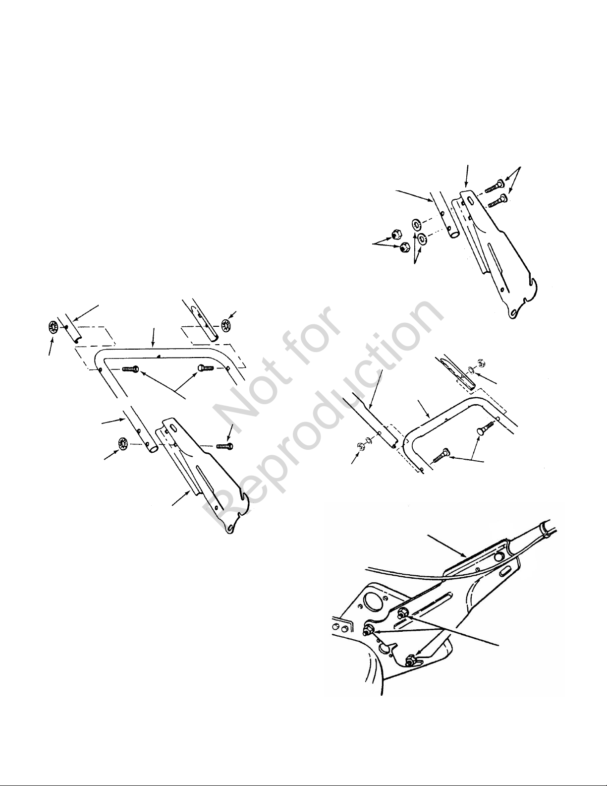
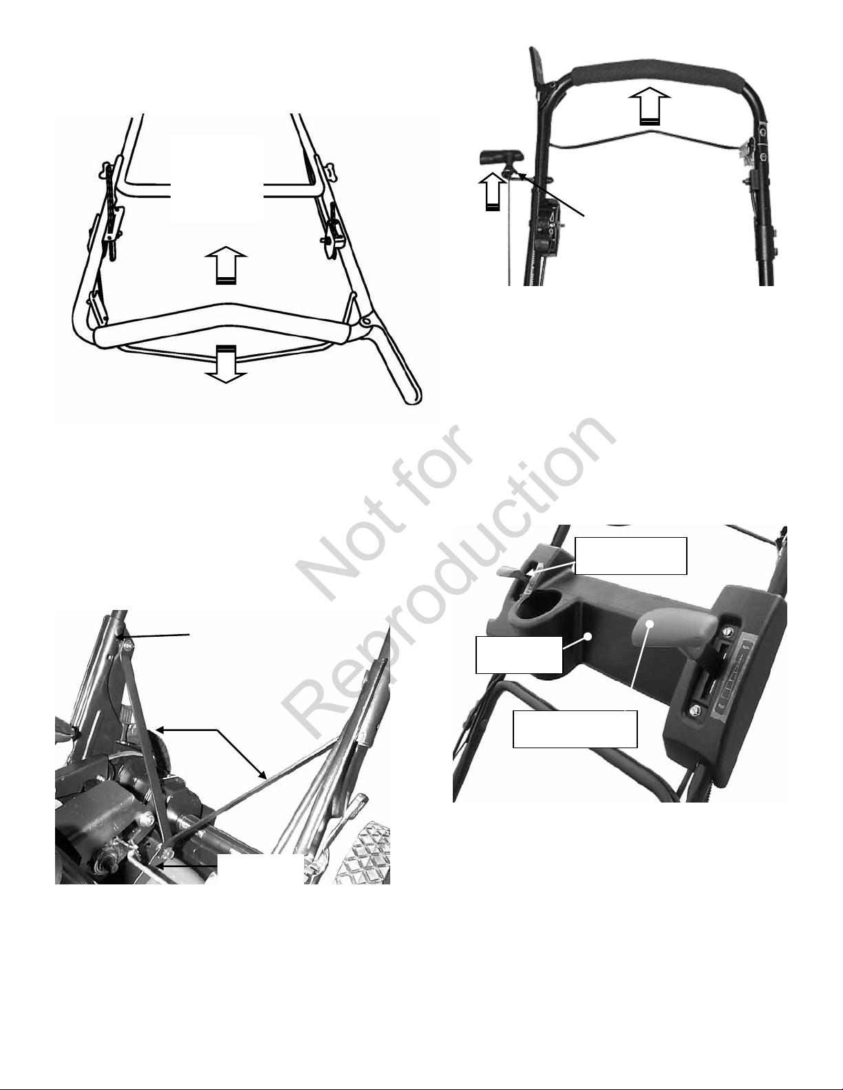
_____ UPPER HANDLE & LOWER HANDLE secured in place and hardware tightened securely.
_____ RECOIL ROPE hooked into rope guide on handle.
_____ OPERATOR CONSOLE installed, engine speed and ground speed handles installed.
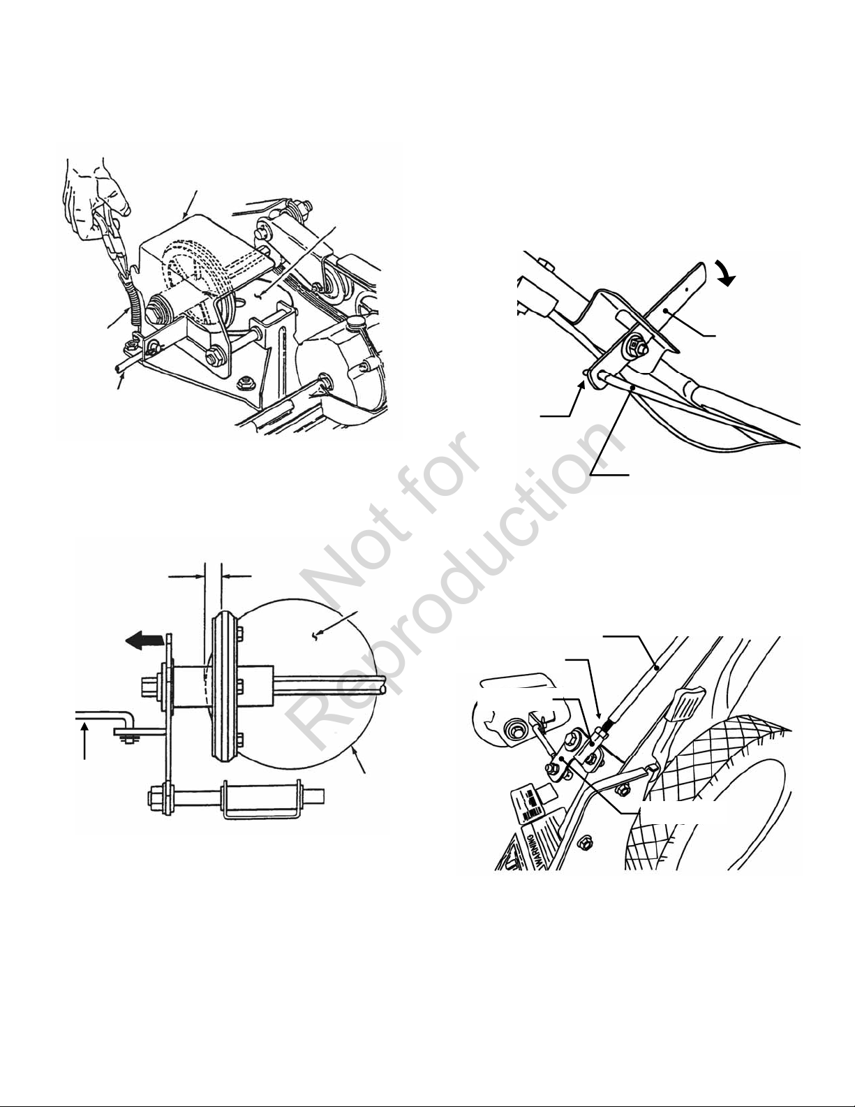
_____ DRIVE ASSEMBLY COMPONENTS installed and adjusted correctly.
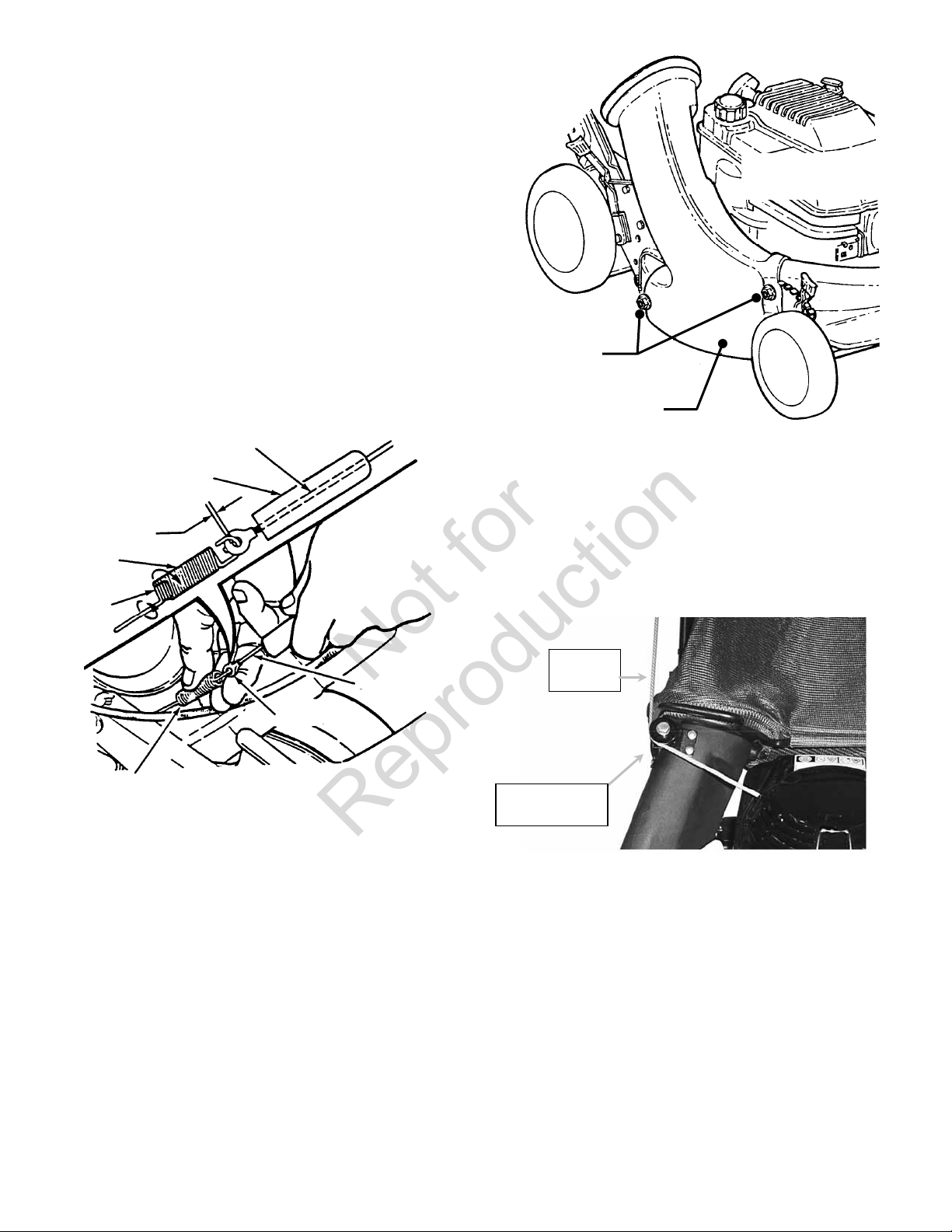
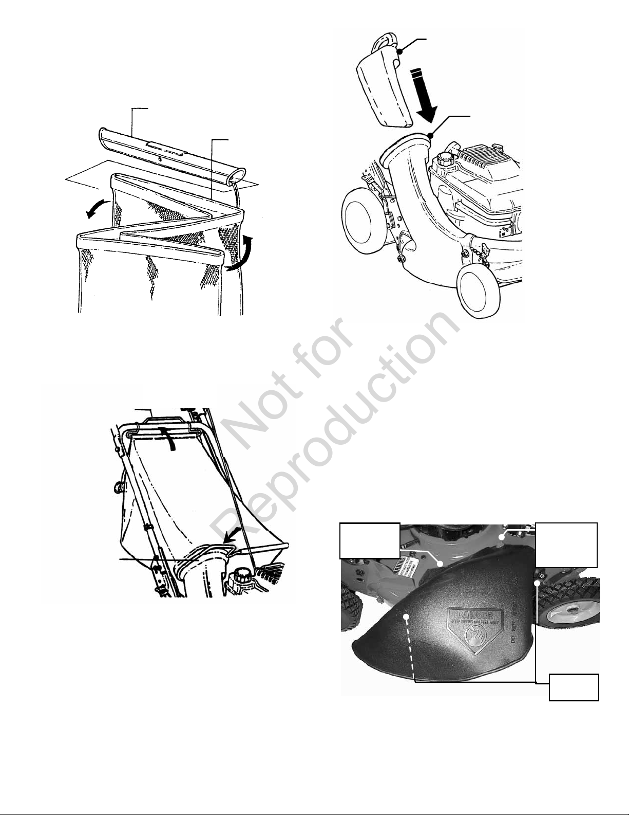
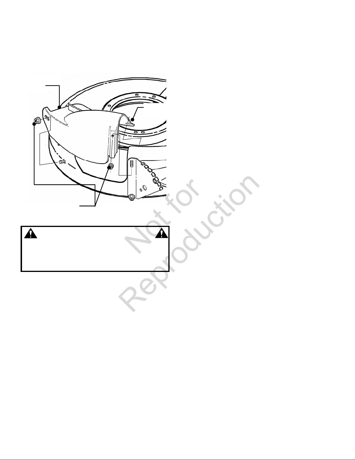
_____ SIDE CHUTE, RECYCLING COVER or GRASS BAG installed correctly on mower.
_____ BLADE retaining bolt(s) checked and tighten securely. (40 ft. lbs. recommended.)
LUBRICATION
_____ ENGINE OIL added to bring level up to full mark on 4-cycle engines (Refer to Engine Manual).
_____ OIL mixed with FUEL in specified ratio (2 Cycle Engines Only).
_____ DIFFERENTIAL grease checked and added if needed.
OPERATIONAL TEST
_____ ENGINE started, engine control settings checked and adjusted as needed.
_____ WHEEL DRIVE checked for proper operation and adjusted as needed.
_____ DRIVE DISC adjustment checked and made.
_____ GROUND SPEED control checked.
CPSC (Consumer Product Safety Commission) COMPLIANCE TEST
_____ BLADE CONTROL stops engine when released.
CONSUMER INFORMATION
Purchase Date ___________________ Model _______________________ Serial No. _______________________
Retailers Name ___________________________________ Signature ____________________________________
Address _____________________________________ City ____________________ State _______ Zip ______
MOWER WILL BE USED COMMERCIALLY? ______ YES______ NO
Purchaser’s Name _________________________________ Signature ____________________________________
Address ____________________________________ City ____________________ State _______ Zip _______
IMPORTANT: This form is to be retained for future reference regarding Warranty, proof of purchase, traceability
for product recall or service, etc.
INSTRUCTION No. 7103223 (Rev. ‘-’, 3/18/2009)
Not for
Reproduction
Table of contents
Other Snapper Lawn Mower Accessories manuals

Snapper
Snapper 1692714 User manual

Snapper
Snapper 1694955 User manual

Snapper
Snapper 63092 User manual

Snapper
Snapper 6-0197 Manual

Snapper
Snapper 1694946 User manual

Snapper
Snapper 3071113 User manual

Snapper
Snapper 4544 Setup guide

Snapper
Snapper 6-3162 User manual

Snapper
Snapper 6-0431 User manual

Snapper
Snapper 6-1276 User manual

Snapper
Snapper 6-0935 User manual

Snapper
Snapper 6-1984 User manual

Snapper
Snapper 6-3041 User manual

Snapper
Snapper 907 User manual

Snapper
Snapper 7600026 User manual

Snapper
Snapper 7600004 User manual

Snapper
Snapper 447575 Administrator Guide

Snapper
Snapper 1690116 User manual

Snapper
Snapper 63305 User manual

Snapper
Snapper 6-3317 User manual