Snelflight QuadPod 2 User manual

1
QuadPod 2 Brushless Quadcopter
Thank you for purchasing the Snelflight QuadPod 2, a compact but powerful brushless-motor
Quadcopter. The model can be built up in about an hour, thanks to its delightfully simple
construction and plain English instructions. Everything is included, no gluing or soldering is
required, and the propellers are pre-balanced for exceptionally smooth performance right from the
outset.
Once assembled the QuadPod 2 is extremely stable, thanks to its state-of-the-art Naza-M Lite flight
controller. Self-levelling and barometric height control are included as standard, and GPS control can
be added to provide fully automatic hovering and return-home failsafe features. The QuadPod 2 is
small enough to fly about indoors, but is also powerful and may be flown outside with confidence,
with flight times of up to 20 minutes. Owing to its straightforward construction it is easy to modify
the QuadPod 2 to add a camera or other payload.
Please read through this manual fully, to acquaint yourself with all the features and functions of your
QuadPod 2. It should be followed carefully during the assembly process.

2
IMPORTANT SAFETY NOTICE
The QuadPod 2 is not a toy. It is a powerful machine which is capable of causing serious
injury if it is not operated safely. This manual should be read carefully before the kit is
assembled and flown.
Always handle the QuadPod 2 carefully, and be mindful that it might start suddenly in the
case of an error or malfunction. Sudden start-ups are fortunately rare, but could happen
under fault conditions.
Always disconnect the battery before leaving the QuadPod 2 unattended, and after use.
Take precautions against propellers flying off the motors. Check them for tightness
frequently, and never point the QuadPod 2 towards anybody or lean over it whilst testing it.
Never fly over people’s heads, or near to children or pets. Make sure that others nearby
know that you are flying the QuadPod 2. The QuadPod 2 is heavy enough to cause serious
injury if it falls on somebody, and sudden stoppages can occur in the event of malfunction.
Remember that the working parts of the QuadPod 2 can get hot during use, particularly the
motors. Other parts can also get hot in the event of a malfunction.
Do not allow the QuadPod 2 to get wet and if it does, disconnect the battery immediately
and thoroughly dry everything before testing carefully.
If a malfunction is suspected, disconnect the battery and remove the propellers before
investigating.
Always treat lithium polymer batteries with great respect, and follow the manufacturer’s
instructions for safe use. Never leave a lithium batteries unattended whilst charging.
If charging a lithium polymer battery indoors, a flameproof container is recommended.
Always disconnect the battery from the QuadPod 2 when not in use. If the battery remains
connected it will be seriously damaged by over-discharge, and may overheat or catch fire
when next charged.
Examine the lithium polymer battery extremely carefully after a crash, and do not use it if
crushed or if the cell envelope has been ruptured.
Remember that lithium polymer batteries contain large amounts of energy. They can
overheat, catch fire or explode if damaged, mistreated or if they fail internally. Always
treat them with the greatest care.
ALWAYS REMEMBER THAT YOU ARE RESPONSIBLE FOR THE SAFE
ASSEMBLY AND OPERATION OF YOUR QUADPOD 2.

3
Packing List
Your kit should contain the following parts. If any of these items is missing then please contact us at
[email protected]. Please note: Product contains nuts.
1) Carbon fibre body, comprising the main cross-shaped airframe, circular upper platform and four
straight bracers.
2) 4 x brushless motors.
3) 4 x electronic speed controllers (ESCs) – small circuits with wires at each end.
4) 4 propellers, pre-mounted onto aluminium spinner adapters.
5) 1 x Naza-M Lite flight controller
6) 1 x Naza power supply module - a black unit with wires at each end.
7) 1 x Naza Remote LED module – the small, square, red and black unit with a single cable on one end.
8) 1 x USB cable.
9) 1 x transparent Lexan dome cover.
10) 6 x 80mm twisted wire cables with “servo” plugs on each end.
11) 2 x 50mm flat extension cables, each with a plug at one end and three pins at the other end.
12) 1 x power distribution cable, with six red “JST” connectors.
13) 1 x packet of black hexagonal spacer posts, together with matching white nylon M3 screws.
14) 1 x packet of small (M2) white nylon screws and matching nuts.
15) 1 x packet of small (M2) steel screws and matching nuts.
16) 1 x packet of small black cable ties.
17) 1 x packet containing various double-sided foam pads.
18) 1 x strip of black adhesive foam.
19) 4 x thick black foam feet.
20) 1 x Allen key (hex key) to fit propeller mounting grub screws.
21) 1 x lithium polymer battery
22) 1 x Snelflight 2.4GHz Spektrum-compatible park flyer receiver.
You will Need
Medium-sized straight screwdriver.
A pair of scissors.
Radio control transmitter: It must have a minimum of 5 channels, with a switch channel that has
adjustable endpoints. A Spektrum transmitter is needed to work with the receiver included in the
QuadPod kit, however any make of RC system may be used (receiver + transmitter), provided it has
these features. Most "computer" systems will work.
1) Assembly
1) Screw the 8 black hexagonal spacer posts to the main carbon frame, using the white M3 nylon screws
provided. It doesn’t matter which way up the carbon frame is oriented. There are 8 holes in the carbon
frame to take the screws, and none of the other holes fit so it is not possible to fix the posts in the
wrong place. Be gentle with your screwdriver – take care not to over-tighten (Photo 1).
1

4
Next, screw the 4 motors onto the ends of the carbon arms, using the M2 nylon screws. Orient each motor
on the frame so that its wires are directed inward at a diagonal angle (Photo 2), and insert the screws from
above. Note that the carbon is drilled for more than one type of motor base plate, so there are some extra
holes. Take care not to bend the motor wires right where they join to the motor, because they can be
damaged. Fasten each screw with an M2 nylon nut under the carbon, and tighten gentle finger tight only.
Once all 4 screws are in place, add a second nut to each for reinforcement (Photo 3). It is crucial not to over
tighten the nuts, otherwise the screws will be damaged. Although metal screws would be stronger, the nylon
screws will pull out in the event of a crash, usually preventing damage to the motor or carbon frame. They
also save significant weight.
2) Attach the 4 motor speed controllers (ESCs) to the carbon arms, using the black cable ties provided.
There are two holes in each carbon arm, to thread the cable tie through. The ESC should be oriented
with the red, black and yellow wires directed outwards towards the motor, and positioned just outside
the inner black spacer post (Photo 4).
3) Next, connect the motors to the ESCs. There are three connections to make for each motor, and the
connectors simply plug together. After making the connections, fold the wires neatly and fasten them
with a cable tie (Photo 5). Make sure that the motor wires are not rubbing on the silver rotating
part, especially the black section where the wires join the motor (see Photo 23 on page 16).
2
3
4
5
5
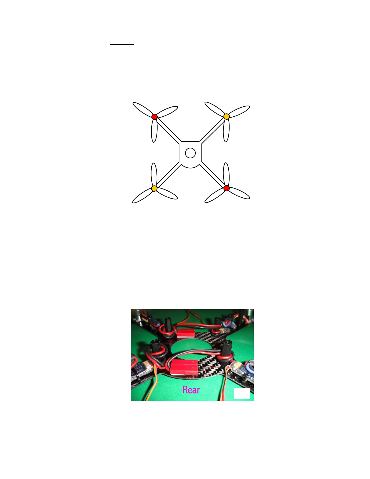
Motor 2
Clockwise
Motor 1
Anticlockwise
Motor 3
Anticlockwise
Motor 4
Clockwise
Fig 1. Motor Identifications and Directions
FRONT
Top
View
It is very important to connect the wires correctly in order that the motors run in the right directions.
For clockwise rotation, connect red – red, black – black and yellow – yellow. To get anticlockwise
rotation, swap any two wires. Figure 1 below details which motors must run clockwise, and
which anticlockwise. Please note the curved side of the frame centre platform, which is designated as
the rear. Please take care to get the connections right; note that they are different from the
original QuadPod.
4) Next, arrange the ESC power leads, which have red connector sockets on their ends. The connectors
should be attached to the carbon frame using the white adhesive foam pads, as shown in Photo 6. Note
that the sockets are oriented towards the right of the aircraft (wires running to the left) but they are
positioned left of centre to allow room for the plugs to be inserted later. One foam pad is wide enough
to attach two connectors, but it should be shortened to 20mm length – the foam cuts easily with
scissors. Excess wire should be kept tidy by wrapping once around the inner black spacer posts.
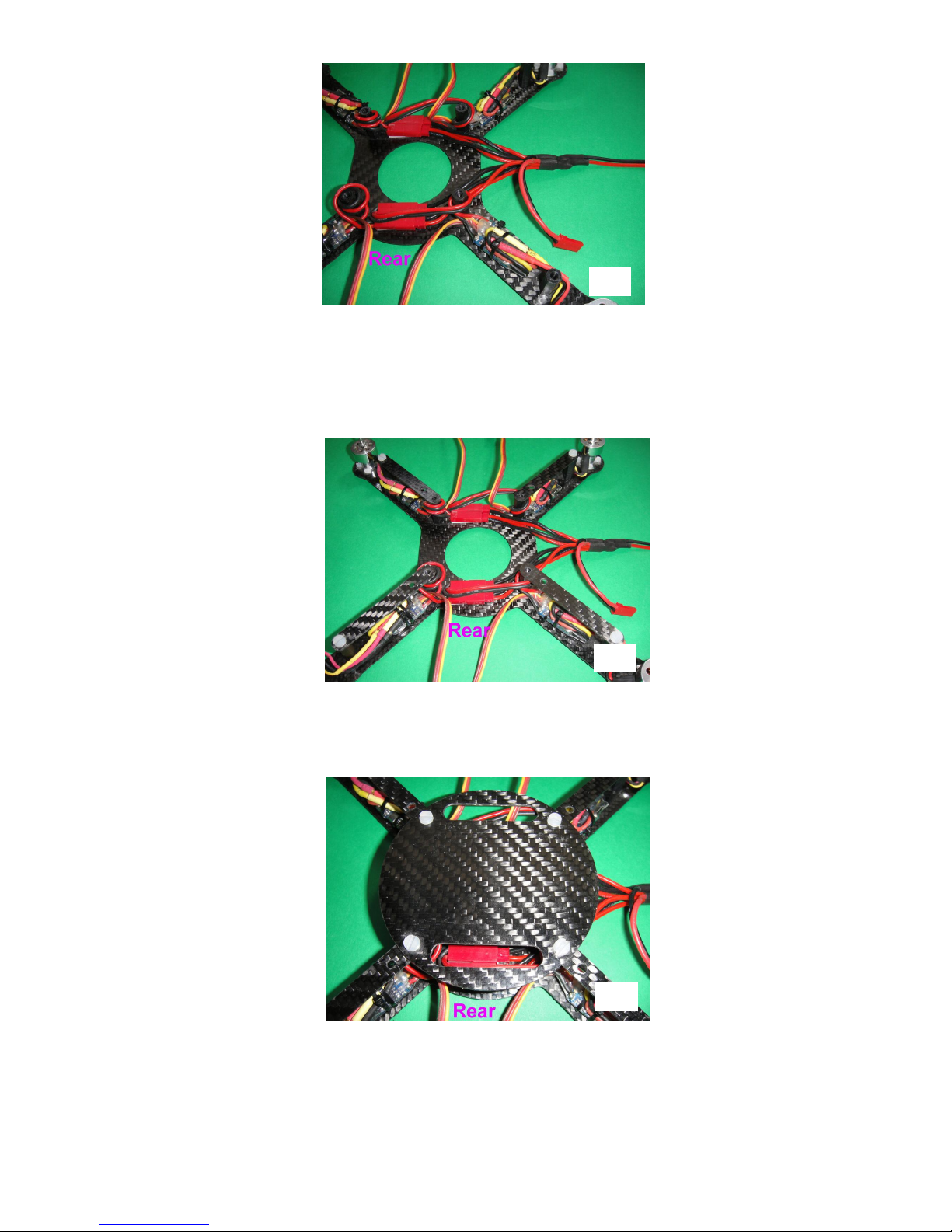
5) Now the power distribution cable should be connected. This has a single red master socket on one end,
and five plugs on the other end. Connect one plug to each ESC socket, and arrange the wiring neatly
so that the master socket exits from the right hand side of the aircraft. The fifth plug should be left
outside the frame until needed (Photo 7).
6
6
6) Next, the carbon bracer parts can be added to the airframe. These connect between the inner and outer
spacer posts along each arm, to form an “upper deck”. Please note that each bracer has two holes at
one end. The other end has a single hole, and this end should be screwed to the outer spacer post. Do
not screw down the other end yet (Photo 8).
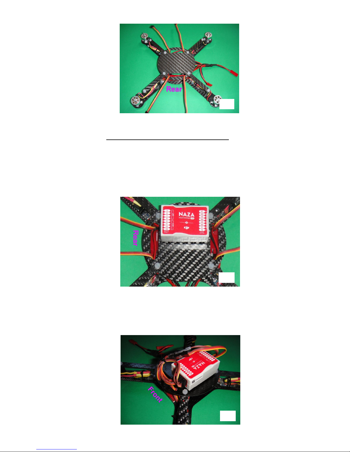
7) Now the circular carbon upper platform should be added. This has two slots, which should be
positioned at the front and rear. Screw the platform onto the four inner spacer posts, screwing through
the ends of the bracers as well, to lock everything together (Photo 9).
8) Next, feed the ESC control leads (orange, red and brown) up through the slots in the upper platform.
The leads from the two rear ESCs should be passed through the rear slot, and the front ESC leads
passed through the front slot (Photo 10).
7
8
9
7
9) Now it is time to install the Naza Lite onto the upper platform. Begin by applying two of the white
double-sided foam pads to the underside, placing one towards each end. Now attach the device to the
central platform. It is very important to get the orientation right. It should be positioned as follows:
a) The text on top should be the right way up when viewed from the right-hand side of the aircraft. The
small red arrow in the white circle should point towards the front.
b) The unit should be mounted on the left-hand side of the platform, and central from back to front. It
should just fit neatly between the two nylon screws, with its left hand edge aligned with the outer
edges of the screw heads (Photo 11).
10) Next, plug the ESC control leads into the terminals labelled M1 to M4 at the front of the Naza Lite.
The numbers correspond to the motor numbers in Fig 1. The orange wires should be positioned at the
bottom. The two rear ESC leads are a little short, so they can be lengthened with the two short
extension cables included. Arrange all the wiring neatly with a cable tie (Photo 12).
10
11
12
8
Receiver Installation and Transmitter Requirements
11) The radio receiver should now be installed in the space next to the Naza Lite. It needs a minimum of
five channels, and it must have a failsafe system which restores the controls to preset positions if the
radio signal is lost. Most modern ones have this. The associated transmitter must have a Channel 5
switch with adjustable endpoints. The switch should preferably have a centre position as well. It is
used to select various flight modes provided by the Naza Lite, and the channel position for each mode
has to be set quite precisely using the endpoint adjustments. This is because failure to hit the correct
spot for the selected mode will be interpreted by the Naza as a loss of radio signal, and the device will
enter its failsafe mode.
Unfortunately this requirement rules out the majority of low cost 5-channel transmitters such as the
Spektrum DX5e and the Snelflight RC system. The Spektrum DX6i can be used, as can most
"computer" radios. Alternatively, Snelflight offers our "Ghost" 6-channel radio system designed
especially for Naza-based multirotors. It has a three-position channel 5 switch pre-calibrated to work
with the Naza Lite, and a self-centring throttle joystick which is ideal for used with the Naza Lite's
barometric height control system. The transmitter also has a rotary control assigned to channel 6,
which can be used for adjusting extra equipment such as a camera gimbal.
The receiver will be connected to the 3-pin sockets at the rear of the Naza Lite, using the twisted-wire
cables provided. It needs to be positioned so that the wires reach neatly, so it is a good idea to
experiment before fixing the receiver to the platform using the black double-sided foam pad provided.
If the receiver is a small one then the pad may need to be cut down to size. When positioning the
receiver, keep in mind the antenna(s). In most instances the antenna will exit towards the front, and the
connections will be at the rear.
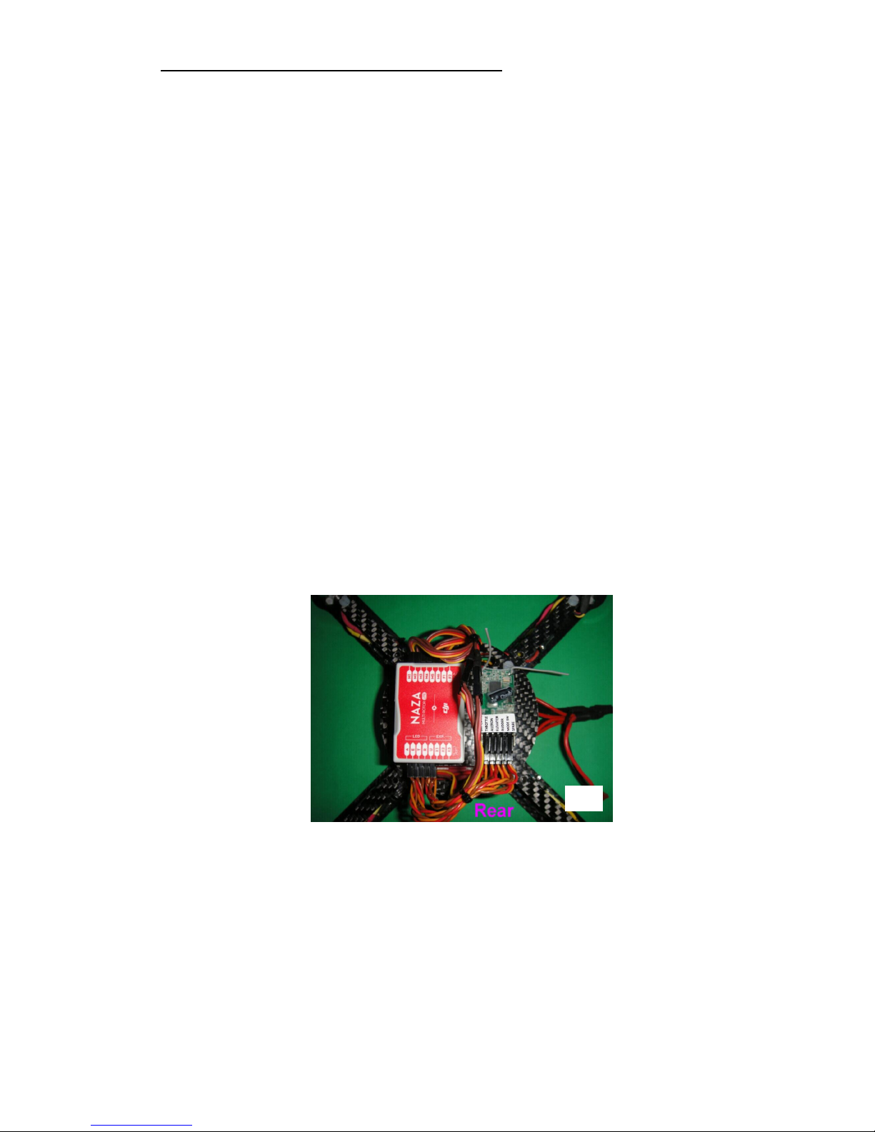
When connecting to the Naza Lite, the orange wires (which carry the control signals) should be at the
bottom. On the Snelflight Spektrum receiver the orange wires should be uppermost. On the "Ghost"
receiver the orange wires should be oriented forwards towards the circuit board. After installation, tidy
up the wiring using a cable tie (Photo 13).
It is important to plug each receiver channel to the correct connector on the Naza Lite. The
connectors are labelled as follows:
A…..Aileron
E…...Elevator
T.......Throttle
R…...Rudder
U…...Mode switch.
Many receivers have the channels named in a similar way. If the channels on the receiver are
numbered instead, then it should be connected up according to Table 1 below. Other brands can be
used - Step 19 provides details of how to find out the correct connections.
13

9
Brand Channel 1
Channel 2
Channel 3
Channel 4
Channel 5
JR/Spektrum Throttle Aileron Elevator Rudder Mode Switch
Snelflight "Ghost" System
Aileron Elevator Throttle Rudder Mode Switch
Futaba Aileron Elevator Throttle Rudder Mode Switch
Hitec Aileron Elevator Throttle Rudder Mode Switch
Table 1 - Receiver Channel Functions
12) Next, the QuadPod should be turned upside down so that its adhesive foam feet can be installed. Each
one fits between the ESC attachment cable tie and the outer M3 airframe screw (Photo 14). This
simple “undercarriage” allows quiet, bounce-free landings. The feet need to be fitted now to provide
clearance under the QuadPod for additional parts added in the next few steps.
13) The Naza Lite's power supply module should be installed now. This is the black widget with cables
emerging at each end. It should be mounted on the underside of the QuadPod at the front, using one of
the white double-sided foam pads. The red and black cables should exit on the aircraft's right side. The
unit's red power socket should be attached nearby using a 6mm x 20mm piece of double-sided foam.
The fifth power plug from the distribution cable should be connected to it (Photo 15).
14) The other cable from the power supply module should now be fed upwards through the front slot in
the QuadPod's upper platform, and led back to the rear of the Naza Lite. The plug should be connected
to the socket labelled "X3", with the orange wire at the bottom (Photo 16).
14
15

10
15) Next, the Naza Lite's remote LED module should be installed. It is the small, flattish square unit with a
red label on one side. Attach it on the underside of the QuadPod at the back, using one of the white
double-sided foam pads. The black cable should exit on the aircraft's left side. Feed this up through the
rear slot in the QuadPod's upper platform, and plug the connector into the socket labelled "LED", with
the red wire on the left (Photos 17 and 18).
Battery
16) The Snelflight 850mAh 3S 25C battery is included. It is small, lightweight and powerful, and has the
correct connector pre-fitted. It provides flight times of 9 - 10 minutes. Other batteries can also be used.
To work, the battery must meet the following requirements:
3S – 11.1V nominal
JST power connector (available as an accessory from our web site)
At least 800mAh
At least 20C discharge rate
Thickness 21mm maximum
Width 37mm maximum
Length is not critical, but batteries longer than 80mm will protrude from the housing.
Weight up to 120g – this allows for capacities up to about 1600mAh.
Charge the battery according to the manufacturer’s instructions, using a suitable lithium polymer
battery charger. The Snelflight battery should be charged at a current from 800mA – 1500mA.
Initial Transmitter Setup
17) Now is the time to set up your transmitter to work with the QuadPod 2. In general it is easier to use
Aeroplane mode if your transmitter has a choice, since it is simpler to set up than Helicopter mode.
The four main control channels should operate fully independently without any mixing functions -
16
17
18

11
make sure that features such as V-Tail and Elevons are turned off. Exponentials can be used if you
wish, but they are generally not necessary. Set all channel endpoints (ATVs) to 100% in both
directions, and centre all trims and sub-trims.
The transmitter servo reverse switches should be set according to Table 2 below:
Brand Channel 1 Channel 2 Channel 3 Channel 4
JR/Spektrum Reversed Reversed Reversed Reversed
Snelflight "Ghost" System Reversed Reversed Normal Normal
Futaba Normal Normal Normal Normal
Hitec Normal Reversed Reversed Normal
Table 2 - Servo Reverse Switch Settings
Please note: Unless you are using the Snelflight "Ghost" RC system, Channel 5 will need its
endpoints set carefully. Details are provided in Step 19.
Binding
18) With a 2.4GHz radio system, the receiver must be bound to the transmitter before it can be used.
Follow the manufacturer’s instructions for this. When binding many receivers it is necessary to
connect a special binding plug, and on some this is a very tight squeeze next to the channel connectors.
It is OK to unplug an adjacent connector to make it easier. When the instructions call for the receiver
to be powered on, plug the lithium battery into the red JST power socket on the QuadPod. There will
be a flurry of multicoloured blinks from the Naza's status LED underneath, but do not worry about
these at the moment.
Once the system has been bound, remove the binding plug, disconnect the lithium battery and restore
the receiver connections.
Before binding the radio system, please position the throttle stick in the centre. When a radio
system is bound, the receiver failsafe settings are often programmed at the same time. If the
radio signal is lost during flight, the receiver will restore the controls to the positions set on the
transmitter at the time of binding. The Naza Lite's auto-recovery system works best if the
throttle reverts to centre in the event of signal disruption.
Transmitter Joystick Calibration and Channel 5 (Mode Switch) Setup
19) Before the QuadPod can be flown, it is necessary perform two more important set-up operations.
Firstly the transmitter's joystick endpoints must be programmed into the Naza Lite. Secondly the
endpoints of the transmitter's channel 5 switch must be set to properly select the flight modes of the
Naza Lite. If you are using the Snelflight "Ghost" RC system, only the first of these has to be done.
To carry out the necessary procedures, the Naza Lite needs to be connected to a computer. Prior to
connection, special software must be installed on the computer. For PCs, this can be downloaded from
the support page on the Snelflight web site at www.snelflight.co.uk. Mac users can download the
required software from the Naza-M Lite support page on the DJI web site at www.dji.com. The
software is called Naza-M Lite Assistant Software v1.00
On a PC, USB drivers must be installed first, by running DJI_WIN_Driver_Installer.exe. Once this
is done, the Naza Lite should be connected to the PC using the USB cable provided. The USB socket
is located at the left-hand end of the Naza Lite power supply module. Power up the QuadPod by
connecting the battery, and wait for the USB link-up process to complete. The Windows application
should then be installed by running NAZA-M LITE_Installer_1.00.exe.
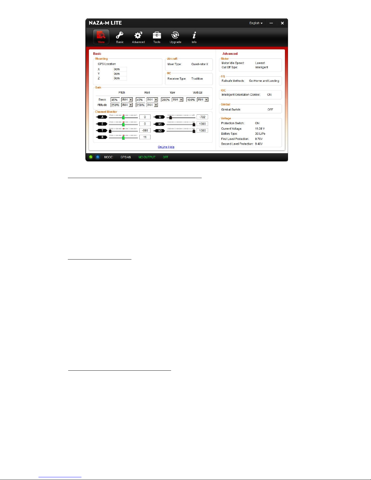
When the program is run, there is a splash screen which has to be dismissed by clicking "SKIP" before
the main window opens. You may be asked to sign in - dismiss this screen also. The main window
looks like the picture on the next page:
12
Checking the RC Channel Functions and Directions
When the transmitter is switched on, the Channel Monitor pointers should move with the joysticks.
They provide a way to determine the right setup for any brand of RC system. Firstly they show to
which control function each joystick is connected, so it is a simple matter to swap the receiver plugs
around until they are all correct. Secondly they show the signal direction for each joystick. The
pointers should move left for left or backward joystick movement, and right for right or forward
joystick movement. If any signal direction is wrong it should be corrected using the related transmitter
reversing switch. We do not recommend changing the Naza Lite direction settings from their defaults
because doing so will invalidate the information in Table 2.
Calibrating the Joysticks
In order to operate correctly it is important that the joystick endpoints are programmed into the Naza
Lite. Begin by switching on the transmitter before powering up the QuadPod. Next, double check that
the trims are centred on all four joystick channels. Once this is done, connect the QuadPod battery.
During the initial multicoloured LED lightshow the Naza Lite zeros itself to the joystick centre
positions, and it is important not to move the joysticks during this time. Please note that it doesn't
matter where the throttle is set. Once this process is completed, the Channel Monitor pointers should
be in the centre with the exception of the throttle one, whose position will depend on the setting of the
joystick. When centred the pointers will be green, changing to black when moved.
To calibrate the joysticks, select the "Basic" button at the top of the window, then choose "RC" from
the row of tabs below. Click the Calibration "START" button, then move both joysticks over their full
ranges several times. A circular motion works well. When done, release the sticks and click "FINISH".
Setting the Channel 5 Switch Endpoints
On the RC window below the joystick calibration, there is a pointer which shows the position of the
Control Mode Switch. To get the aircraft to work properly, the pointer must land on "Atti" at the left-
hand end, and "Manual" at the right-hand end, turning them blue. If the switch has a centre position
then this should land the pointer on "Atti" in the middle. It has to hit the designated regions quite
centrally otherwise it selects "Failsafe" on one of the adjacent areas. The small regions at each end
count as failsafe as well. The point of this is simple: Unless the transmitter signal is spot-on, the Naza
Lite will assume that there is a problem and enter failsafe mode. Please note that this is not the same
thing as the radio receiver's failsafe, which simply sets the controls to preset positions if the
radio signal is lost. When the Naza Lite enters failsafe mode it will automatically land the
aircraft, and if GPS is installed the Naza will fly the aircraft home and land it.
13
To position the pointer correctly, the switch endpoints need to be adjusted in the transmitter. On most
radios this can be done in real time whilst transmitting, so it is easy enough to move the pointer around
until it hits each mark. Try to position it in the centre of the small workable range so that minor shifts
won't cause failure. The transmitter should have a separate setting for each end, plus it may have a
centre adjustment for a 3-position switch.
Finding the right settings within the transmitter may take some time, calling for diligent study of the
instruction manual! They are often buried in sub-menus, and require a particular sequence of button
entries to select the required function and then to change it.
When all settings are complete, disconnect the USB cable, unplug the QuadPod's battery and
turn off the transmitter.
Please note: If it is necessary to re-bind the RC system in the future, then it is important to set
the receiver's failsafe for Channel 5 to a position where it will trigger the Naza Lite's failsafe, in
other words, to an incorrect position for selecting one of the Naza's flight modes. This is to make
sure that the Naza will enter failsafe if the transmitter signal is lost. It is easiest to set one
Channel 5 endpoint to 100% temporarily, whilst the RC system is bound. This will then be set as
the receiver's Channel 5 failsafe position. Make sure it works correctly!
Preliminary Testing
20) It is a good idea to test the QuadPod at this stage, before the propellers are fitted. This will prevent
possible accidents if something goes wrong.
Begin by switching on the transmitter and then powering up the QuadPod – note that it's
important to do it in that order, so that the Naza Lite can acquire the joystick centres correctly.
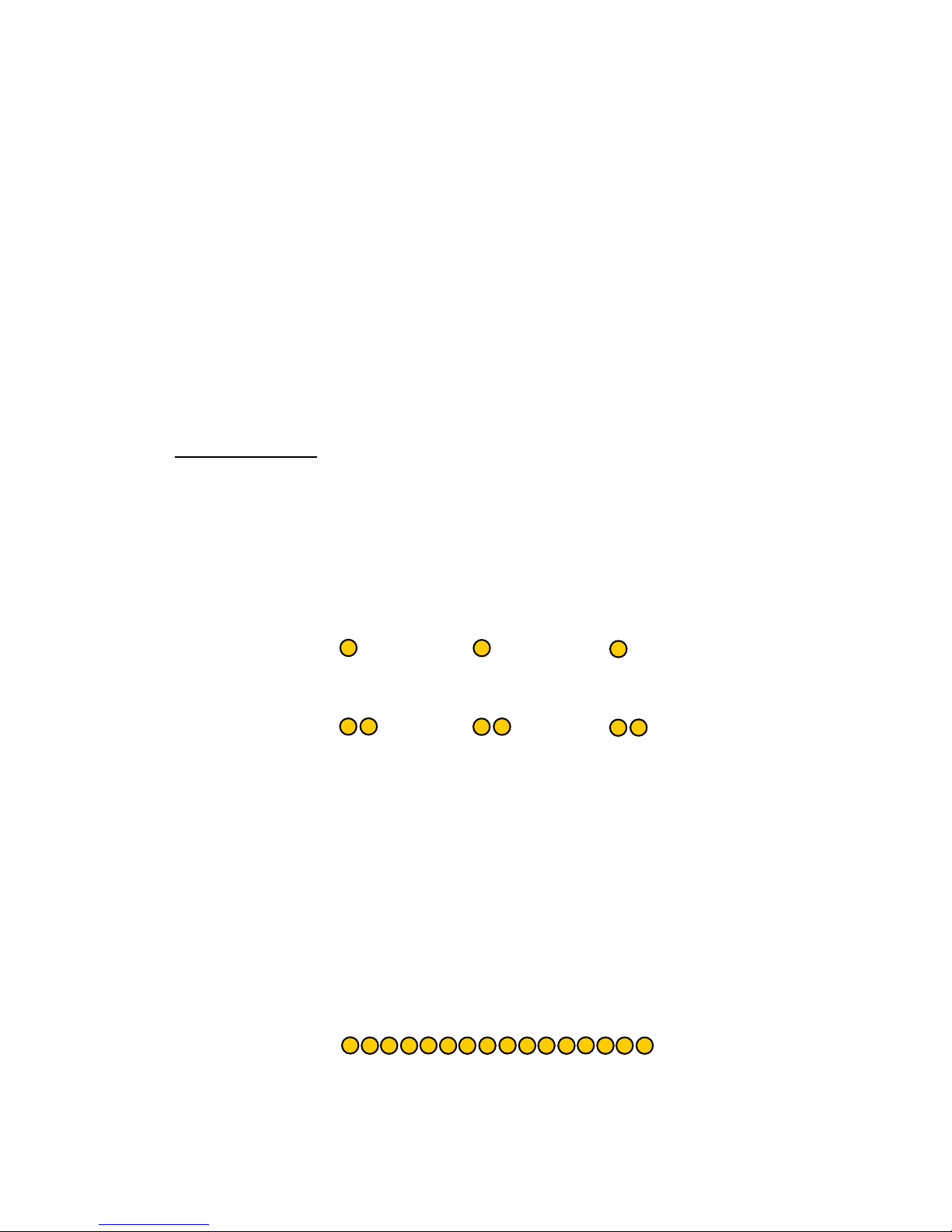
After its initial multi-coloured light display during which the joysticks should not be moved,
the Naza's status LED should settle down into regular yellow blinks spaced about two seconds
apart, like this:
If any of the joysticks is moved off-centre (except the throttle), then each yellow blink will
become a double one, like this:
When the motors are running, the double blinks will also appear if the throttle is off-centre. To
get the single blinks the throttle stick must be centred, whereupon the barometric control will try
to maintain constant height. Stick positions above or below centre will cause the aircraft to
climb or descend.
Prior to starting the motors, the single yellow blinks indicate that the QuadPod is ready to fly.
If the yellow blinks do not appear at all then it means that the QuadPod is set to Manual flight
mode. In this mode it is not self-levelling and barometric height control is inoperative. We
recommend switching to self levelling (called "Atti" mode), using the Channel 5 switch on the
transmitter.
If the LED gives continuous rapid yellow blinks, then it means that the transmitter signal is not
correct, and the Naza Lite has entered failsafe mode:
Check that the receiver has linked to the transmitter - most have an indicator light to confirm
this. Otherwise, the problem is most likely caused by incorrect setting of the Channel 5
endpoints in the transmitter. Please refer to Step 19 above.
Please see Page 19 for a summary of the various status LED indications and their meanings.
. . . etc
. . . etc
. . . etc

14
If all is well, stand the QuadPod on a level surface and try starting the motors. To do so, pull both
joysticks back into the "cross-eyed" (toe-in) position, like this:
The motors should start. They should also start if the joysticks are pulled into the "toe-out" position,
or if both are pointed down left or right. It doesn't matter if some of these positions don't work - it just
means that one of the joystick endpoints falls slightly short in one direction.
Having started the motors, the throttle needs to be raised above 10% within a couple of seconds,
otherwise they will stop again. It's worth getting into the habit of releasing the right-hand stick before
raising the throttle, so that the direction controls are at neutral before the motors rev-up. Otherwise the
propellers will run unevenly and the aircraft might tip over. Bring the throttle up a little way and then
check the directions of motor rotation. This can be done by gently resting a finger on each motor's
shiny cylindrical surface. The motors should turn in the directions shown in Figure 1. If any of the
directions are wrong then they must be corrected by swapping any two of the three motor wires -
switch off and disconnect the battery first!
If the throttle is the self-centring type, then its trim should be adjusted to get single yellow blinks when
both joysticks are released.
To turn off the motors, lower the throttle to minimum and wait for three seconds. Repeating the "start"
joystick positions will stop the motors quickly.
Completing the Assembly
21) Having tested the basic functioning of the QuadPod, the assembly can be completed ready for the first
flight. Make sure all the wiring is neat and secure. It is important to locate receiver antenna(s)
properly. The Snelflight Spektrum-compatible receiver has two short antennas. We pointed the left
hand one upwards and the right hand one out sideways. This perpendicular arrangement is
recommended for all 2.4GHz systems with dual antennas (Photo 13). The best setup will depend on
the particular receiver. It is always a good idea to keep the antennas away from the carbon fibre body.
Install the battery into the space under the upper platform, by sliding it in from the left hand side. A
strip of adhesive foam is provided in the kit – if necessary one or two layers of this should be applied
to the underside of the upper platform to pad out the battery and hold it in place.
To keep the battery lead tidy, the QuadPod's main power connector should be attached to the underside
of the body using a 6mm x 20mm piece of white double-sided foam (Photo 19).
19

15
Propellers
22) Now, propellers! Notice that these have black adhesive tape attached to some blades. The purpose of
this tape is to balance the propellers. It is very important that the propellers are well balanced, as out-
of-balance propellers will vibrate and cause unsteady flight. In extreme cases the motors or their
mountings may be damaged. Therefore, please observe the following cautions:
Do not disturb the tape on the blades.
Do not loosen the propeller from its spinner adapter. The propeller + spinner is balanced as a
unit, and will not remain balanced if disturbed.
Note that the propeller is assembled onto the spinner with the grub screw aligned 180º opposite
the “blank” blade (the other two blades have text embossed on them). If the propeller should
become loose in a crash for instance, it will usually remain quite well balanced if it is re-
tightened in this same orientation.
It is a good idea to check the aircraft for vibration before a flight, by holding it from underneath
and revving it up. Get used to the way it feels and sounds when it is running smoothly, and if it
doesn’t feel right, look for the problem.
A common cause of vibration after a crash is poor blade “tracking”. A propeller’s three blades
should all run level with each other when viewed edge-on. If one blade is bent slightly upwards
or downwards, it will cause vibration. Poor tracking is easily spotted if the propeller is gently
spun up whilst the aircraft is viewed from the side in front of a white surface (Photos 20 and 21).
Blades can get bent if knocked in a crash, but they can often be straightened again. However if
there is any sign of cracking of the plastic at the blade root then the propeller should be replaced.
DO NOT FLY UNBALANCED OR DAMAGED PROPELLERS
23) Each propeller carries a red or yellow sticker, to indicate whether it should run clockwise or
anticlockwise. Fit the propellers onto the motor shafts, in the locations indicated in Figure 1 (Note that
the positions are opposite to those on the original QuadPod!) Ensure that each propeller is oriented so
that its grub screw (set screw) bears onto the flat area of the motor shaft (Photo 22), then tighten the
grub screw with the Allen key (hex key) provided. Take care not to over-tighten the grub screws - it is
possible to strip the aluminium threads with extreme force.
22
20
21
16
2) Test Flying
Congratulations! Your QuadPod 2 is now ready for its first flight. We recommend test-flying the aircraft
before installing the dome cover for easy access to the innards in case something has to be adjusted.
Test flights are best performed indoors if possible. Choose the largest space available; a clear area 8 feet
square should be considered the minimum.
Pre-Flight Checks
These checks should be performed before all flying sessions, and also after any crash or tumble:
Check that the propellers are screwed tightly onto the motor shafts.
Check that the motors are firmly screwed down onto the carbon frame (nylon nuts).
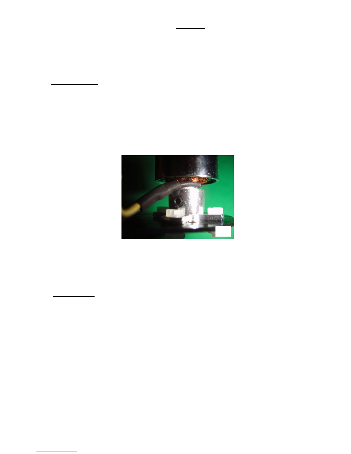
Check that the motors are tightly screwed into their base plates. There are two grub screws per motor
for this, and it is very important that they are not loose (Photo 23). They can be tightened with the
Allen key provided. When doing this hold the motor mount firmly – do not use the nylon mounting
screws to resist the force of tightening.
Switch on the transmitter and connect the QuadPod's Lithium battery. Wait for the LED to begin its
regular yellow blinks, then pick up the aircraft and hold it from underneath, grasping it firmly. Hold
the aircraft horizontally, and make absolutely sure that the propellers are well away from your
body and face. Now start the motors and gradually rev them up, listening and feeling for signs of
vibration.
The First Flight
We are assuming in this section that the pilot has some experience flying model rotorcraft. If not, then we
strongly recommend obtaining the help of an experienced pilot for the test flights. Please also refer to the
control function diagram on page 18.
If all is well, place the aircraft in the centre of the flying area for its first flight. Stand about four feet
behind it so that it is facing away from you –the curved rear part of the carbon body should be towards you
and the flashing yellow LED should be visible. Start the motors and gently raise the throttle. At about half-
throttle the aircraft should be light on the ground, and a little more will cause it to take off. Take it up to a
height of about 6 feet and then centre the throttle (single yellow blinks). The aircraft should maintain
height and keep itself level, but please note that it will not hold its position automatically. The pilot must
use the right hand joystick to guide the aircraft around the flying area, or to make corrections to keep it
hovering in one place. Although the aircraft will self-level when the right-hand joystick is centred, it will
not stop moving by itself. The pilot needs to apply opposite corrective control to slow the aircraft when
needed.
If the transmitter has a self-centring throttle then the QuadPod should maintain its height when the joystick
is released – adjust the trim to get the single yellow blinks from the LED. However please note that
barometric height control is not perfect, and small deviations in height are normal.
23

17
Battery Care / Low Charge Indicator
The Naza Lite has a built-in battery voltage monitor, which provides a warning of low charge level. The
status LED will change to continuous rapid red blinking when the power is low:
The QuadPod should be landed immediately when this happens. The final “running out of juice” occurs
quite suddenly, so it is important to descend to a safe height as soon as the warning appears. The QuadPod
will fly until the battery is discharged down to around 3V/cell. This is OK, but it is important to re-charge
the battery as soon as possible; it should not be left completely discharged. Please note that batteries should
not be stored fully charged either, as this will impair their performance in less than a week. If the battery
will not be flown within a few hours, it should be charged to about 50% for storage – some chargers have a
program for this. Never leave the battery connected to the QuadPod. It will be damaged by over-
discharge.
Installing the Dome Cover
The QuadPod is supplied with a transparent dome cover made from extremely tough Lexan – the material
used for bullet proof windows! It will offer real protection for the innards of your QuadPod, so it is well
worth installing, unless it is absolutely necessary to save the weight to allow for a heavy payload. In
addition to providing impact protection, the dome will also protect the electronics if it starts raining.
However, the QuadPod is not suitable for flying in wet weather, with or without dome!
The dome rests on the four carbon arm bracers, which have screw holes which align to holes in the edge of
the Lexan. It should be screwed down with the steel M2 nuts and bolts provided. Tip: position each nut and
hold in place with a fingertip, before inserting the screw. Steel screws are used for two reasons:
They prevent the dome from coming off, even in a severe crash. The Lexan can withstand heavy
impacts, so this combination offers a lot of protection.
When tightly screwed down, the dome locks the QuadPod’s four arms together, improving their
torsional rigidity.
Depending upon the receiver used and the antenna arrangements required, it may be necessary to make
some small holes in the dome for the wires to exit. In our build using the Snelflight receiver we made a
hole in the right hand side of the dome for one antenna to pass through. We let the other antenna lie within
the dome, pointing upwards.
Some receivers have two short antennas, and some have two long ones. Depending upon the arrangement,
holes might be needed in various locations, such as a hole on each side part-way up the dome, so that the
two antennas can protrude at 45º like little horns. Generally if there are two antennas then they should be
mounted perpendicular to one another. Holes can be made with a large heated needle or similar tool, a fine-
pointed soldering iron, or of course a small drill.
Because the QuadPod is relatively small, it will not be flown at a great distance. Therefore it may be
adequate to mount the two antennas within the dome, avoiding the need for holes.
General Flying Tips
During rapid descents, the QuadPod can get into its own turbulent downdraft, causing a very bumpy
ride! The cure is either to descend more slowly, or else to descend whilst flying along rather than
from a hover.
If the radio signal is lost (or the transmitter is switched off), the QuadPod will immediately begin
executing an emergency landing. Pilot control will be restored if the radio signal is recovered.
. . . etc

18
After an emergency landing the motors will remain running, so that the aircraft is ready to fly if the
radio signal comes back. If it is not possible to restore the radio link then it will be necessary to
disconnect the battery to power down the aircraft.
Aircraft Control Functions
The diagram below shows the effect that each joystick has on the aircraft in flight.

19
Status LED Indications
Before Take-off and During Flight
System start and self-check: Do not move the joysticks
during this time.
Atti flight mode: The aircraft will auto-level, and
barometric height control operates.
If one or more transmitter joysticks is moved off-
centre, then the yellow blinks become double.
In manual flight mode, there are no blinks: The
aircraft will not self-level, and the throttle is
completely manual with no barometric height control.
Failsafe auto-land - this happens if the transmitter
signal is lost.
Low flight battery voltage warning: Land as soon as
possible. When the voltage drops a little further, the
aircraft will start to descend automatically in an
attempt to land before control is lost.
This signal will also appear in other fault conditions,
such as a disconnected receiver lead.
USB connected.
3) Specifications
Size: 9" (23cm) diagonal motor-to-motor
Weight: 280g including supplied battery
Flight time: About 9 minutes with recommended battery
Battery: Snelflight 850mAh 3S 25C Lithium Polymer
Power consumption: Around 60W at hover (280g weight)
Payload: Up to 100g in addition to recommended battery
Maximum flight weight: 380g
. . . etc
. . . etc
. . . etc
. . . etc

20
V 1.0 Revised 27-05-2015
Snelflight Ltd, Unit 11C Oakway Court, Meadowfield Industrial Estate,
Durham, DH7 8XA, United Kingdom.
Web: www.snelflight.co.uk Email: [email protected]o.uk
Table of contents


