Snell Advanced Media MV-800 User manual

www.s-a-m.com
User Manual
MV-800 Integrated Multiviewer
for use in Sirius 830, 840 and 850 routers

MV-800 Integrated Multiviewer
Issue 1 Rev 6 Page 2 © 2017 SAM

MV-800 Integrated Multiviewer Contents
Issue 1 Rev 6 Page 3 © 2017 SAM
Contents
1 About this Manual . . . . . . . . . . . . . . . . . . . . . . . . . . . . . . . . . . . . . . . . . . . . . . . . . . . . 7
1.1 Contact Details . . . . . . . . . . . . . . . . . . . . . . . . . . . . . . . . . . . . . . . . . . . . . . . . . . . 7
1.2 Copyright and Disclaimer . . . . . . . . . . . . . . . . . . . . . . . . . . . . . . . . . . . . . . . . . . . 7
1.3 Trademarks . . . . . . . . . . . . . . . . . . . . . . . . . . . . . . . . . . . . . . . . . . . . . . . . . . . . . . 7
2 Warnings and Precautions. . . . . . . . . . . . . . . . . . . . . . . . . . . . . . . . . . . . . . . . . . . . . 9
2.1 Explanation of Safety Symbols . . . . . . . . . . . . . . . . . . . . . . . . . . . . . . . . . . . . . . . 9
2.2 Safety Warnings . . . . . . . . . . . . . . . . . . . . . . . . . . . . . . . . . . . . . . . . . . . . . . . . . . 9
2.3 Lithium Batteries . . . . . . . . . . . . . . . . . . . . . . . . . . . . . . . . . . . . . . . . . . . . . . . . . . 9
2.4 Fiber Output Modules Warning . . . . . . . . . . . . . . . . . . . . . . . . . . . . . . . . . . . . . . 10
2.5 Power Requirements. . . . . . . . . . . . . . . . . . . . . . . . . . . . . . . . . . . . . . . . . . . . . . 10
2.6 Cable Management . . . . . . . . . . . . . . . . . . . . . . . . . . . . . . . . . . . . . . . . . . . . . . . 10
2.7 Compliance Standards . . . . . . . . . . . . . . . . . . . . . . . . . . . . . . . . . . . . . . . . . . . . .11
3 Product Overview . . . . . . . . . . . . . . . . . . . . . . . . . . . . . . . . . . . . . . . . . . . . . . . . . . . 13
3.1 Integrated Multiviewer Benefits . . . . . . . . . . . . . . . . . . . . . . . . . . . . . . . . . . . . . . 13
3.2 Typical User Applications . . . . . . . . . . . . . . . . . . . . . . . . . . . . . . . . . . . . . . . . . . 14
3.3 Features . . . . . . . . . . . . . . . . . . . . . . . . . . . . . . . . . . . . . . . . . . . . . . . . . . . . . . . 14
3.4 Integration into Sirius 800 Routers . . . . . . . . . . . . . . . . . . . . . . . . . . . . . . . . . . . 16
3.5 MV-800 Main Input and Output Connections . . . . . . . . . . . . . . . . . . . . . . . . . . . 17
3.6 MV-800 Components. . . . . . . . . . . . . . . . . . . . . . . . . . . . . . . . . . . . . . . . . . . . . . 18
3.7 MV-800-DT Desktop Multiviewer Option Overview . . . . . . . . . . . . . . . . . . . . . . . 20
3.8 Order Codes . . . . . . . . . . . . . . . . . . . . . . . . . . . . . . . . . . . . . . . . . . . . . . . . . . . . 23
3.9 Terminology . . . . . . . . . . . . . . . . . . . . . . . . . . . . . . . . . . . . . . . . . . . . . . . . . . . . . 24
3.10 Video Wall design . . . . . . . . . . . . . . . . . . . . . . . . . . . . . . . . . . . . . . . . . . . . . . . 26
3.11 MV-800 Set up. . . . . . . . . . . . . . . . . . . . . . . . . . . . . . . . . . . . . . . . . . . . . . . . . . 26
4 Hardware Module Installation. . . . . . . . . . . . . . . . . . . . . . . . . . . . . . . . . . . . . . . . . . 27
4.1 Introduction . . . . . . . . . . . . . . . . . . . . . . . . . . . . . . . . . . . . . . . . . . . . . . . . . . . . . 27
4.2 Initial Checks and Actions . . . . . . . . . . . . . . . . . . . . . . . . . . . . . . . . . . . . . . . . . . 28
4.2.1 Power Checks . . . . . . . . . . . . . . . . . . . . . . . . . . . . . . . . . . . . . . . . . . . . . . . 28
4.2.2 Fitting of Video SFP’s to MV-800 Rear Panel . . . . . . . . . . . . . . . . . . . . . . . 29
4.3 Identifying Modules and Slots in Router . . . . . . . . . . . . . . . . . . . . . . . . . . . . . . . 31
4.4 Removal and then Fitting of Modules . . . . . . . . . . . . . . . . . . . . . . . . . . . . . . . . . 39
4.4.1 Removal Preliminaries . . . . . . . . . . . . . . . . . . . . . . . . . . . . . . . . . . . . . . . . 39
4.4.2 Module Removal Procedure . . . . . . . . . . . . . . . . . . . . . . . . . . . . . . . . . . . . 40
4.4.3 Fitting Preliminaries. . . . . . . . . . . . . . . . . . . . . . . . . . . . . . . . . . . . . . . . . . . 41
4.4.4 Module Fitting Procedure . . . . . . . . . . . . . . . . . . . . . . . . . . . . . . . . . . . . . . 43
4.5 Connecting Cables . . . . . . . . . . . . . . . . . . . . . . . . . . . . . . . . . . . . . . . . . . . . . . . 45
4.5.1 Connecting the Network and Multiviewer Display Output(s) . . . . . . . . . . . . 45
5 MV-800 Hardware Modules. . . . . . . . . . . . . . . . . . . . . . . . . . . . . . . . . . . . . . . . . . . . 47
5.1 MV-800 Multiviewer Front Module (5934) . . . . . . . . . . . . . . . . . . . . . . . . . . . . . . 48
5.1.1 Front Module Status LED Indicators . . . . . . . . . . . . . . . . . . . . . . . . . . . . . . 49
5.1.2 DIP switches . . . . . . . . . . . . . . . . . . . . . . . . . . . . . . . . . . . . . . . . . . . . . . . . 50
5.1.3 Engineering connectors . . . . . . . . . . . . . . . . . . . . . . . . . . . . . . . . . . . . . . . 50
5.2 MV-800-RP Multiviewer Rear Panel (1312) . . . . . . . . . . . . . . . . . . . . . . . . . . . . 51
5.2.1 Connectors . . . . . . . . . . . . . . . . . . . . . . . . . . . . . . . . . . . . . . . . . . . . . . . . . 52
5.2.2 Rear Panel LEDs . . . . . . . . . . . . . . . . . . . . . . . . . . . . . . . . . . . . . . . . . . . . 53
5.2.3 LTC and GPIO Connector Pin-outs . . . . . . . . . . . . . . . . . . . . . . . . . . . . . . . 54
5.2.4 Example: Driving LEDs from the GPI Outputs . . . . . . . . . . . . . . . . . . . . . . 55
6 MV-800 Module Booting . . . . . . . . . . . . . . . . . . . . . . . . . . . . . . . . . . . . . . . . . . . . . . 57
6.1 Module Booting . . . . . . . . . . . . . . . . . . . . . . . . . . . . . . . . . . . . . . . . . . . . . . . . . . 57
6.2 Start up Splash screen . . . . . . . . . . . . . . . . . . . . . . . . . . . . . . . . . . . . . . . . . . . . 57
7 Sirius 800 Router Configuration . . . . . . . . . . . . . . . . . . . . . . . . . . . . . . . . . . . . . . . 59

MV-800 Integrated Multiviewer Contents
Issue 1 Rev 6 Page 4 © 2017 SAM
7.1 Matrix Output Ports . . . . . . . . . . . . . . . . . . . . . . . . . . . . . . . . . . . . . . . . . . . . . . . 59
7.1.1 Router Output Ports . . . . . . . . . . . . . . . . . . . . . . . . . . . . . . . . . . . . . . . . . . 59
7.1.2 Matrix Destinations . . . . . . . . . . . . . . . . . . . . . . . . . . . . . . . . . . . . . . . . . . . 59
7.2 Module Configuration . . . . . . . . . . . . . . . . . . . . . . . . . . . . . . . . . . . . . . . . . . . . . 60
7.2.1 Module Type . . . . . . . . . . . . . . . . . . . . . . . . . . . . . . . . . . . . . . . . . . . . . . . . 60
7.2.2 Sirius Router Module Addresses. . . . . . . . . . . . . . . . . . . . . . . . . . . . . . . . . 60
8 MV-800 RollCall Configuration. . . . . . . . . . . . . . . . . . . . . . . . . . . . . . . . . . . . . . . . . 65
8.1 Control Panel Connection to MV-800 . . . . . . . . . . . . . . . . . . . . . . . . . . . . . . . . . 66
8.2 Using RollCall MV-800 Menu screens. . . . . . . . . . . . . . . . . . . . . . . . . . . . . . . . . 69
8.3 Initial MV-800 Configuration . . . . . . . . . . . . . . . . . . . . . . . . . . . . . . . . . . . . . . . . 70
8.4 Further MV-800 Configuration . . . . . . . . . . . . . . . . . . . . . . . . . . . . . . . . . . . . . . . 71
8.5 RollCall MV-800 System-Setup Screen. . . . . . . . . . . . . . . . . . . . . . . . . . . . . . . . 72
8.5.1 “System Reset” box. . . . . . . . . . . . . . . . . . . . . . . . . . . . . . . . . . . . . . . . . . . 74
8.5.2 “Product” box. . . . . . . . . . . . . . . . . . . . . . . . . . . . . . . . . . . . . . . . . . . . . . . . 75
8.5.3 “Network Settings” box . . . . . . . . . . . . . . . . . . . . . . . . . . . . . . . . . . . . . . . . 75
8.5.4 “NTP Servers” box. . . . . . . . . . . . . . . . . . . . . . . . . . . . . . . . . . . . . . . . . . . . 76
8.5.5 “Router Controller Settings” box . . . . . . . . . . . . . . . . . . . . . . . . . . . . . . . . . 76
8.5.6 “RollCall Settings” box. . . . . . . . . . . . . . . . . . . . . . . . . . . . . . . . . . . . . . . . . 76
8.5.7 “Streamed Input” box. . . . . . . . . . . . . . . . . . . . . . . . . . . . . . . . . . . . . . . . . . 77
8.5.8 “Output Format” box . . . . . . . . . . . . . . . . . . . . . . . . . . . . . . . . . . . . . . . . . . 77
8.5.9 “Reference Input” box . . . . . . . . . . . . . . . . . . . . . . . . . . . . . . . . . . . . . . . . . 77
8.5.10 “Information” box . . . . . . . . . . . . . . . . . . . . . . . . . . . . . . . . . . . . . . . . . . . . 78
8.5.11 System Reset to Effect Changes. . . . . . . . . . . . . . . . . . . . . . . . . . . . . . . . 78
8.6 RollCall MV-800 Video Alarms Screen . . . . . . . . . . . . . . . . . . . . . . . . . . . . . . . . 79
8.7 RollCall MV-800 Audio Alarms Screen . . . . . . . . . . . . . . . . . . . . . . . . . . . . . . . . 80
8.8 RollCall MV-800 Reference Alarms. . . . . . . . . . . . . . . . . . . . . . . . . . . . . . . . . . . 82
8.9 RollCall MV-800 Ancillary Alarms . . . . . . . . . . . . . . . . . . . . . . . . . . . . . . . . . . . . 83
8.10 RollCall MV-800 Layout Screen . . . . . . . . . . . . . . . . . . . . . . . . . . . . . . . . . . . . 84
8.11 RollCall TSL Screen . . . . . . . . . . . . . . . . . . . . . . . . . . . . . . . . . . . . . . . . . . . . . 85
8.12 RollCall GPIO Screen . . . . . . . . . . . . . . . . . . . . . . . . . . . . . . . . . . . . . . . . . . . . 86
8.13 RollCall Timer Control Screen . . . . . . . . . . . . . . . . . . . . . . . . . . . . . . . . . . . . . . 87
9 MV-800 License Installation . . . . . . . . . . . . . . . . . . . . . . . . . . . . . . . . . . . . . . . . . . . 89
9.1 License Files . . . . . . . . . . . . . . . . . . . . . . . . . . . . . . . . . . . . . . . . . . . . . . . . . . . . 89
9.2 License Installation Procedure . . . . . . . . . . . . . . . . . . . . . . . . . . . . . . . . . . . . . . 89
9.2.1 Add License to RollCall Control Panel . . . . . . . . . . . . . . . . . . . . . . . . . . . . 89
9.2.2 Install License on the MV-800 . . . . . . . . . . . . . . . . . . . . . . . . . . . . . . . . . . . 90
10 MV-800 Software Upgrade . . . . . . . . . . . . . . . . . . . . . . . . . . . . . . . . . . . . . . . . . . . 93
10.1 Software Upgrade Package . . . . . . . . . . . . . . . . . . . . . . . . . . . . . . . . . . . . . . . 93
10.2 Software Upgrade Procedure . . . . . . . . . . . . . . . . . . . . . . . . . . . . . . . . . . . . . . 93
10.2.1 Stage 1: Add Upgrade Package to RollCall. . . . . . . . . . . . . . . . . . . . . . . . 94
10.2.2 Stage 2: Install the Upgrade on the Multiviewer Unit. . . . . . . . . . . . . . . . . 95
11 Basic Video Wall . . . . . . . . . . . . . . . . . . . . . . . . . . . . . . . . . . . . . . . . . . . . . . . . . . . 97
11.1 Fusion Video Wall Terminology . . . . . . . . . . . . . . . . . . . . . . . . . . . . . . . . . . . . . 98
11.2 MV-800 Default Project . . . . . . . . . . . . . . . . . . . . . . . . . . . . . . . . . . . . . . . . . . . 99
11.2.1 Pull Default Project from Multiviewer (Connected Multiviewer Project). . 100
11.2.2 Make a Simple Change to the Default Project. . . . . . . . . . . . . . . . . . . . . 101
11.2.3 Push the Project to the Multiviewer . . . . . . . . . . . . . . . . . . . . . . . . . . . . . 103
11.2.4 Exercising the alarm . . . . . . . . . . . . . . . . . . . . . . . . . . . . . . . . . . . . . . . . 103
11.3 Fusion Client Home Screen. . . . . . . . . . . . . . . . . . . . . . . . . . . . . . . . . . . . . . . 104
11.4 Creating a New Project . . . . . . . . . . . . . . . . . . . . . . . . . . . . . . . . . . . . . . . . . . 105
11.4.1 New Project - Multiviewer project . . . . . . . . . . . . . . . . . . . . . . . . . . . . . . 105
11.4.2 New Project - Connected Multiviewer Project . . . . . . . . . . . . . . . . . . . . . 108
11.5 Opening an Existing Project . . . . . . . . . . . . . . . . . . . . . . . . . . . . . . . . . . . . . . .111
11.6 Opening a Recent Project . . . . . . . . . . . . . . . . . . . . . . . . . . . . . . . . . . . . . . . . .112
11.7 Fusion Client Project Screen . . . . . . . . . . . . . . . . . . . . . . . . . . . . . . . . . . . . . . .113
11.8 Making a Basic Video Wall Layout . . . . . . . . . . . . . . . . . . . . . . . . . . . . . . . . . .114

MV-800 Integrated Multiviewer Contents
Issue 1 Rev 6 Page 5 © 2017 SAM
11.8.1 Create a New Multiviewer Project . . . . . . . . . . . . . . . . . . . . . . . . . . . . . . .114
11.8.2 Create the Video Wall . . . . . . . . . . . . . . . . . . . . . . . . . . . . . . . . . . . . . . . .116
11.8.3 Import a Logo into the Project . . . . . . . . . . . . . . . . . . . . . . . . . . . . . . . . . 121
11.8.4 Create Custom Tiles . . . . . . . . . . . . . . . . . . . . . . . . . . . . . . . . . . . . . . . . 122
11.8.5 Add Custom Tiles to the Wall . . . . . . . . . . . . . . . . . . . . . . . . . . . . . . . . . 125
11.8.6 Assign Multiviewer Inputs to Wall Video Tiles . . . . . . . . . . . . . . . . . . . . . 127
11.8.7 Push the Project to the Multiviewer . . . . . . . . . . . . . . . . . . . . . . . . . . . . . 129
11.9 Fusion Client Wall Layouts . . . . . . . . . . . . . . . . . . . . . . . . . . . . . . . . . . . . . . . 130
11.10 Themes . . . . . . . . . . . . . . . . . . . . . . . . . . . . . . . . . . . . . . . . . . . . . . . . . . . . . 132
11.10.1 Baseline Default Theme . . . . . . . . . . . . . . . . . . . . . . . . . . . . . . . . . . . . 132
11.10.2 Creating Themes . . . . . . . . . . . . . . . . . . . . . . . . . . . . . . . . . . . . . . . . . . 132
11.10.3 Applying Themes to a Wall . . . . . . . . . . . . . . . . . . . . . . . . . . . . . . . . . . 133
11.10.4 Applying a Style to a Widget . . . . . . . . . . . . . . . . . . . . . . . . . . . . . . . . . 134
12 Configuring Alarms. . . . . . . . . . . . . . . . . . . . . . . . . . . . . . . . . . . . . . . . . . . . . . . . 135
12.1 Unit Alarms . . . . . . . . . . . . . . . . . . . . . . . . . . . . . . . . . . . . . . . . . . . . . . . . . . . 135
12.2 Input Alarms . . . . . . . . . . . . . . . . . . . . . . . . . . . . . . . . . . . . . . . . . . . . . . . . . . 136
13 TSL Support. . . . . . . . . . . . . . . . . . . . . . . . . . . . . . . . . . . . . . . . . . . . . . . . . . . . . . 139
13.1 TSL Protocol Tally Settings . . . . . . . . . . . . . . . . . . . . . . . . . . . . . . . . . . . . . . . 139
13.1.1 Specifying Multiviewer TSL Tally Mode . . . . . . . . . . . . . . . . . . . . . . . . . . 139
13.1.2 Specifying Index Parameters for each UMD . . . . . . . . . . . . . . . . . . . . . . 140
13.1.2.1TSL Protocol Version 3.1 . . . . . . . . . . . . . . . . . . . . . . . . . . . . . . . . . . . . . . . . 140
13.1.2.2TSL Protocol Version 5.0 . . . . . . . . . . . . . . . . . . . . . . . . . . . . . . . . . . . . . . . . 140
14 MV-800-DT Desktop Video Wall . . . . . . . . . . . . . . . . . . . . . . . . . . . . . . . . . . . . . . 143
14.1 System Requirements . . . . . . . . . . . . . . . . . . . . . . . . . . . . . . . . . . . . . . . . . . . 144
14.2 Installation and Preparation. . . . . . . . . . . . . . . . . . . . . . . . . . . . . . . . . . . . . . . 146
14.2.1 Installation Stages . . . . . . . . . . . . . . . . . . . . . . . . . . . . . . . . . . . . . . . . . . 146
14.3 Configure an MV-800 unit . . . . . . . . . . . . . . . . . . . . . . . . . . . . . . . . . . . . . . . . 147
14.4 Project Settings for MV-800-DT. . . . . . . . . . . . . . . . . . . . . . . . . . . . . . . . . . . . 148
14.5 Video Wall and Video Sources . . . . . . . . . . . . . . . . . . . . . . . . . . . . . . . . . . . . 153
14.6 Launching Fusion Client Video Wall . . . . . . . . . . . . . . . . . . . . . . . . . . . . . . . . 157
14.6.1 Running Fusion Client. . . . . . . . . . . . . . . . . . . . . . . . . . . . . . . . . . . . . . . 157
14.6.2 Fusion Client Window Controls . . . . . . . . . . . . . . . . . . . . . . . . . . . . . . . . 159
14.6.3 Switching into Design Mode . . . . . . . . . . . . . . . . . . . . . . . . . . . . . . . . . . 159
Appendix A MV-800 Multiviewer Specification . . . . . . . . . . . . . . . . . . . . . . . . . . . . 161
A.1 Power . . . . . . . . . . . . . . . . . . . . . . . . . . . . . . . . . . . . . . . . . . . . . . . . . . . . . . . . 161
A.2 Inputs . . . . . . . . . . . . . . . . . . . . . . . . . . . . . . . . . . . . . . . . . . . . . . . . . . . . . . . . 161
A.3 Display Outputs. . . . . . . . . . . . . . . . . . . . . . . . . . . . . . . . . . . . . . . . . . . . . . . . . 161
A.4 Input Video Standards . . . . . . . . . . . . . . . . . . . . . . . . . . . . . . . . . . . . . . . . . . . 162
A.5 IP Outputs . . . . . . . . . . . . . . . . . . . . . . . . . . . . . . . . . . . . . . . . . . . . . . . . . . . . . 163
A.6 MV-800-RP Rear Panel Connectors. . . . . . . . . . . . . . . . . . . . . . . . . . . . . . . . . 164
A.7 Monitoring and Alarms . . . . . . . . . . . . . . . . . . . . . . . . . . . . . . . . . . . . . . . . . . . 165
A.8 Video Wall Screen Display . . . . . . . . . . . . . . . . . . . . . . . . . . . . . . . . . . . . . . . . 166
A.9 Software Versions. . . . . . . . . . . . . . . . . . . . . . . . . . . . . . . . . . . . . . . . . . . . . . . 167
Appendix B MV-800-DT License Installation . . . . . . . . . . . . . . . . . . . . . . . . . . . . . . 169
B.1 Install License Server . . . . . . . . . . . . . . . . . . . . . . . . . . . . . . . . . . . . . . . . . . . . 169
B.2 Lock Code for License Host PC . . . . . . . . . . . . . . . . . . . . . . . . . . . . . . . . . . . . 172
B.3 Add MV-800-DT License to License Server . . . . . . . . . . . . . . . . . . . . . . . . . . . 174
Appendix C VLC Installation . . . . . . . . . . . . . . . . . . . . . . . . . . . . . . . . . . . . . . . . . . . 177
Appendix D Fusion Client Software Installation for Multiviewer Applications. . . 179
D.1 Supported OS . . . . . . . . . . . . . . . . . . . . . . . . . . . . . . . . . . . . . . . . . . . . . . . . . . 179
D.2 Supported SAM Fusion Client software version . . . . . . . . . . . . . . . . . . . . . . . . 179
D.3 Installation. . . . . . . . . . . . . . . . . . . . . . . . . . . . . . . . . . . . . . . . . . . . . . . . . . . . . 179

MV-800 Integrated Multiviewer Contents
Issue 1 Rev 6 Page 6 © 2017 SAM

MV-800 Integrated Multiviewer User Manual Contact Details About this Manual
Issue 1 Rev 6 Page 7 © 2017 SAM
1 About this Manual
This MV-800 Integrated Multiviewer user manual describes how to install, configure and
operate the MV-800 multiviewer in the Sirius 830, 840 and 850 routers.
Refer to the appropriate Sirius 800 router Installation Manuals for details on how to unpack,
install and test the Sirius 800 routers and the Sirius 800 User manual for router details.
If you have any questions regarding the installation and setup of your product, please contact
SAM Customer Support.
1.1 Contact Details
Customer Support
For details of our Regional Customer Support Offices and contact details please visit the SAM
web site and navigate to Support/247-Support.
www.s-a-m.com/support/247-support/
Customers with a support contract should call their personalized number, which can be found
in their contract, and be ready to provide their contract number and details.
1.2 Copyright and Disclaimer
Copyright protection claimed includes all forms and matters of copyrightable material and
information now allowed by statutory or judicial law or hereinafter granted, including without
limitation, material generated from the software programs which are displayed on the screen
such as icons, screen display looks etc.
Information in this manual and any software are subject to change without notice and does
not represent a commitment on the part of SAM.
Reproduction or disassembly of embedded computer programs or algorithms is prohibited.
No part of this publication can be transmitted or reproduced in any form or by any means,
electronic or mechanical, including photocopy, recording or any information storage and
retrieval system, without permission being granted, in writing, by the publishers or their
authorized agents.
SAM operates a policy of continuous improvement and development. SAM reserves the right
to make changes and improvements to any of the products described in this document
without prior notice.
1.3 Trademarks
Microsoft, Microsoft Windows and Windows are either registered trademarks or trademarks of
Microsoft Corporation in the United States and/or other countries.
All other trademarks or registered trademarks are the property of their respective owners.

MV-800 Integrated Multiviewer User Manual Trademarks About this Manual
Issue 1 Rev 6 Page 8 © 2017 SAM
MV-800 Integrated Multiviewer User Manual Explanation of Safety Symbols Warnings and Precautions
Issue 1 Rev 6 Page 9 © 2017 SAM
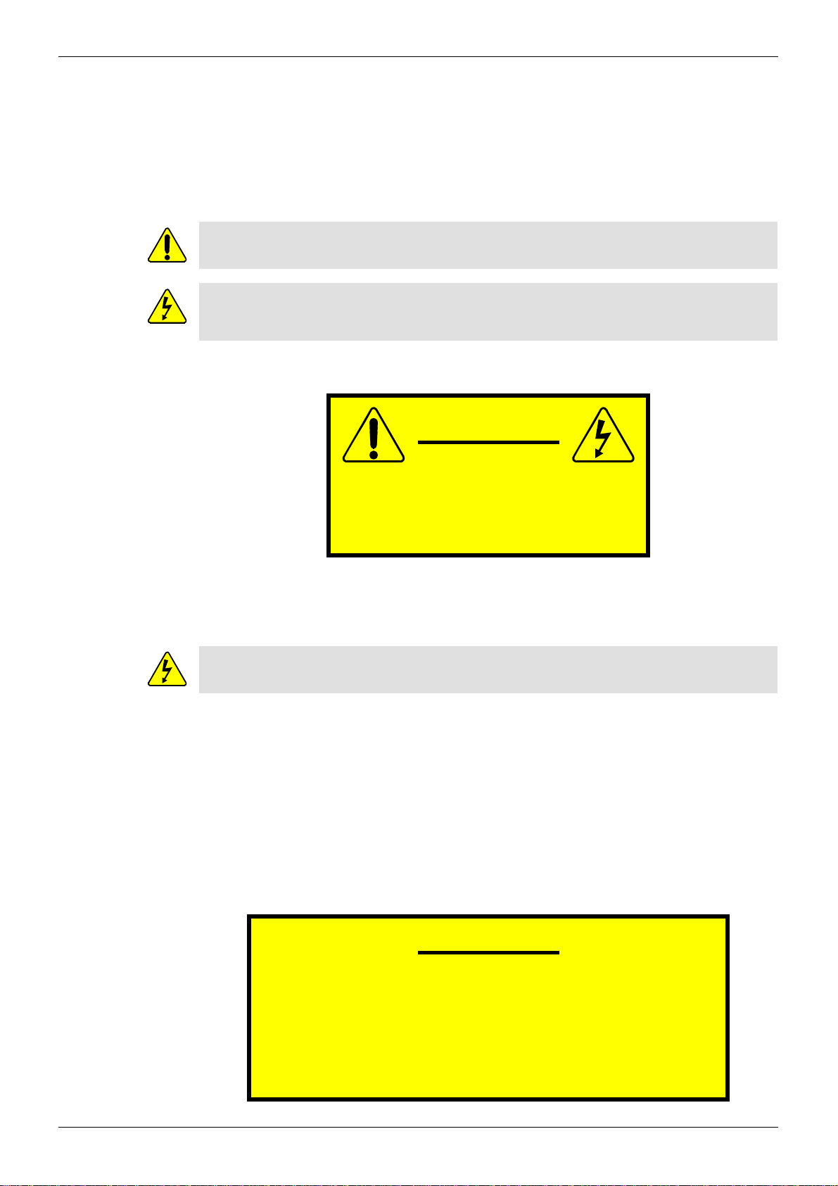
2 Warnings and Precautions
The hardware modules covered by this user manual are not mains powered. The hardware
modules must be fitted into a mains powered frame, host equipment, for operation.
2.1 Explanation of Safety Symbols
2.2 Safety Warnings
CAUTION: These servicing instructions are for use by qualified personnel only. To reduce the
risk of electric shock, do not perform any servicing other than that contained in the Operating
Instructions unless you are qualified to do so. Refer all servicing to qualified service
personnel.
Always ensure that the host equipment is properly earthed and power connections correctly
made.
The host equipment must be supplied from a power system providing a PROTECTIVE
EARTH connection and having a neutral connection which can be reliably identified.
The power circuit breakers or switches supplying power to the host equipment should be
close to the unit and easily accessible.
2.3 Lithium Batteries
The MV-800 Integrated Multiviewer card contains a Lithium battery.
This symbol refers the user to important information contained in the accompanying
literature.
This symbol indicates that hazardous voltages are present inside the router frame.
No user serviceable parts inside.
This system should only be serviced by trained personnel.
To reduce the risk of electric shock, do not expose the host equipment to rain or moisture.
CAUTION
RISK OF ELECTRIC SHOCK
DO NOT REMOVE COVERS
NO USER SERVICABLE PARTS
REFER SERVICING TO QUALIFIED
PERSONNEL ONLY
This equipment contains a lithium battery
There is a danger of explosion if this is replaced incorrectly
Replace only with the same type from the same manufacturer.
Dispose of used batteries in accordance with local
and national laws/regulations.
Batteries should only be replaced by trained service technicians
CAUTION

MV-800 Integrated Multiviewer User Manual Fiber Output Modules Warning Warnings and Precautions
Issue 1 Rev 6 Page 10 © 2017 SAM
2.4 Fiber Output Modules Warning
2.5 Power Requirements
Before adding an MV-800 Integrated Multiviewer to a Sirius 800 router check that the power
supplies fitted can supply sufficient power to the router. See the Sirius 800 User Manual for
router power requirements and contact SAM Support for advice.
2.6 Cable Management
It is important that the cabling to and from the multiviewer is correctly labelled and routed.
This will simplify the work required if the installation needs to be changed or added to at a
future date.
LASER SAFETY
The average optical output power does not exceed 0 dBm (1mW) under normal
operating conditions. Unused optical outputs should be covered to prevent direct
exposure to the laser beam.
Even though the power of these lasers is low, the beam should be treated with caution
and common sense because it is intense and concentrated. Laser radiation can cause
irreversible and permanent damage of eyesight. Please read the following guidelines
carefully:
• Make sure that a fiber is connected to the board's fiber outputs before power is
applied. If a fiber cable (e.g. patch cord) is already connected to an output, make
sure that the cable's other end is connected, too, before powering up the board.
•Do not look in the end of a fiber to see if light is coming out. The laser
wavelengths being used are totally invisible to the human eye and can cause
permanent damage. Always use optical instrumentation, such as an optical
power meter, to verify light output.
• Cables connected to the multiviewer must be fitted with adequate vertical and
horizontal strain relief to avoid twisting of the rear panels causing damage to the
MV-800 rear connectors and loss of electrical/signal connection to the multiviewer
or monitor displays.
• Cables connected to the multiviewer should be routed so they do not cover any of
the frame fan exhausts as this can restrict airflow through the router.
MV-800 Integrated Multiviewer User Manual Compliance Standards Warnings and Precautions
Issue 1 Rev 6 Page 11 © 2017 SAM
2.7 Compliance Standards
This equipment complies with the following standards:
EN60950-1 2006
Safety of information Technology Equipment Including Electrical Business Equipment.
UL1419 (3rd Edition) - UL File E193966
Standard for Safety - Professional Video and Audio equipment
EMC Standards
This unit conforms to the following standards:
EN 55032:2012 (Class A)
EN 55103-2:2009 (Environment E2)
EN 61000-3-2:2014 (Class A)
EN 61000-3-3:2013
Federal Communications Commission Rules, 47 CFR: Part 15, Subpart B (Class A)
EMC Performance of Cables and Connectors
SAM products are designed to meet or exceed the requirements of the appropriate European
EMC standards. In order to achieve this performance in real installations it is essential to use
cables and connectors with good EMC characteristics.
All signal connections (including remote control connections) shall be made with screened
cables terminated in connectors having a metal shell. The cable screen shall have a
large-area contact with the metal shell.
COAXIAL CABLES
Coaxial cables connections (particularly serial digital video connections) shall be made with
high-quality double-screened coaxial cables such as Belden 1694A or Belden 1505A.
D-TYPE CONNECTORS
D-type connectors shall have metal shells making good RF contact with the cable screen.
Connectors having “dimples” which improve the contact between the plug and socket shells,
are recommended.
Warning:
This equipment is compliant with Class A of CISPR 32.
In a residential environment this equipment may cause radio interference.

MV-800 Integrated Multiviewer User Manual Compliance Standards Warnings and Precautions
Issue 1 Rev 6 Page 12 © 2017 SAM

MV-800 Integrated Multiviewer User Manual Integrated Multiviewer Benefits Product Overview
Issue 1 Rev 6 Page 13 © 2017 SAM
3 Product Overview
The all new MV-800 Integrated Multiviewer brings a wealth of previously unseen capabilities
in an integrated multiviewer. One or more can be added into any existing Sirius 800 router.
The MV-800 is available from SAM as an option on a new Sirius 800 router from the factory or
as an option to be installed in the field. A single MV-800 can drive up to 12 multiviewer display
monitors.
3.1 Integrated Multiviewer Benefits
• No additional space required.
• Lower cost.
• Reduced power consumption and cooling requirements.
• No signal cabling, simplified installation.
• Control and monitoring integration using open protocols.
• H.264 streaming of all video sources on the multiviewer video wall.
• Flexible screen design from multi-channel quad-splits to flexible multi-tile screen
layouts, shown in Figure 1.
Figure 1 MV-800 Multiviewer Video Walls and Screens

MV-800 Integrated Multiviewer User Manual Typical User Applications Product Overview
Issue 1 Rev 6 Page 14 © 2017 SAM
3.2 Typical User Applications
The MV-800 Integrated Multiviewer is ideal for any user application that requires single or
multiple displays. For example: Play out control rooms, multi-channel play out, studio
galleries, OB trucks, post-production suites, and signal lines monitoring areas.
3.3 Features
With the development of advanced technology within the MV-800 Integrated Multiviewer,
SAM can offer some unique, powerful features:
Integrates into all Sirius 800 systems:
• Uses built-in dedicated multiviewer output slots.
• Uses a dedicated internal multiviewer crosspoint.
• Access to all router video inputs
• No loss of router capabilities:
• Main router outputs.
• Redundancy.
• Routing capacity.
• Processing capability.
• More than one MV-800 per router, see Table 1.
Display up to 48 router inputs per MV-800 on multiviewer screens:
• Sirius 830 – select from the router’s 288 inputs.
• Sirius 840/850 – select from the router’s 576 inputs.
Total screen layout flexibility:
• Additionally display web pages, automation play lists, device status screens etc.
• Display status and alarms from external devices.
• Drag and Drop objects onto the screen layout.
• Adjustable layering, transparencies and fine-positioning.
Flexible alarm capability:
• Monitoring of video, audio and metadata, with alarm notification.
• Intelligent monitoring of external devices, with configurable on-screen alarms.
• Control and acknowledgement of alarms from hardware- and soft-panels.
Sirius 800 Router Maximum number of MV-800’s
Sirius 830 2-off
Sirius 840 3-off
Sirius 850 2-off
Table 1 MV-800 in Sirius 800 series routers

MV-800 Integrated Multiviewer User Manual Features Product Overview
Issue 1 Rev 6 Page 15 © 2017 SAM
Up to 12 display outputs per MV-800, connections to monitor display screens:
• 3G 1080p
• Display outputs:
• 4 display outputs on baseline MV-800 model.
• Up to 12 display outputs per MV-800, enabled with MV-800 options.
• Four display outputs can be used together to provide a 4K UHD quad-link.
• Display outputs use flexible SFP modules.
• Outputs can be a mixture of 3G SDI dual-coax or dual-fiber SFP’s, or
single-HDMI SFP’s.
Streaming out of MV-800 inputs:
• MV-800 multiviewer inputs are H.264-encoded to create streamed copies which can
then be streamed out over IP.
• These MV-800 input video streams can be viewed on a desktop PC with appropriate
software.
Desktop Multiviewer Option for MV-800 input video streams:
• License option provides live video wall capabilities to a PC.
• Live video wall displayed on a PC monitor: live video, audio levels and alarms.
• IP video streams from one or more MV-800 units.
• Applications include: confidence monitoring, compliance monitoring.
Future Option - Advanced broadcast media monitoring.
• Biometric signature generation for all MV-800 inputs. Resilient.
• Low-bandwidth video and audio signatures streamed with media.
• Applications include: Lip sync, Channel mapping detection, Confidence
Monitoring. Identification and comparison.
Up to 48 internal scalers:
• One per MV-800 input. One per video wall “video” tile.
• Each scaled picture may be used multiple times on the multiviewer video wall.

MV-800 Integrated Multiviewer User Manual Integration into Sirius 800 Routers Product Overview
Issue 1 Rev 6 Page 16 © 2017 SAM
3.4 Integration into Sirius 800 Routers
The MV-800 Multiviewer fits into dedicated multiviewer module slots in a Sirius 800 router
frame. More than one MV-800 may be fitted to a router.
The Sirius 800 internal router architecture allows the MV-800 to tap into the signal flow within
the router at the input signals, just before the main router crosspoint. Figure 2 shows a Sirius
800 router block diagram which includes up to three MV-800 Integrated Multiviewer units.
The MV-800 uses a Sirius Multiviewer Crosspoint module (MV Crosspoint) to select which of
the router inputs the MV-800 can monitor. This is an auxiliary crosspoint which is dedicated to
multiviewer use. A Sirius 800 Multiviewer Crosspoint module is required for the MV-800.
Thus, the addition of an MV-800 Integrated Multiviewer into a Sirius router retains the router’s:
• Main outputs.
• Main Crosspoint redundancy.
• Processing capability on all router inputs and outputs.
Figure 2 Sirius 800 Router block diagram, with MV-800 Integrated Multiviewer(s)
MV-800 inputs,
48 inputs per MV-800
(selectable from all router inputs)
MV-800 Display Outputs
to monitor screens
(up to 12 per MV-800)
Up to 3 MV-800’s

MV-800 Integrated Multiviewer User Manual MV-800 Main Input and Output Connections Product Overview
Issue 1 Rev 6 Page 17 © 2017 SAM
3.5 MV-800 Main Input and Output Connections
Figure 3 shows the main MV-800 inputs and outputs, comprising:
•48inputs:
• Selected from all router inputs via the MV Crosspoint module.
• Mapped to router destinations.
For mapping details, see Table 12, “Router Destination Matrix Port Number
Mapping for MV-800 module slots,” on page 59.
• Ethernet connections:
• 2-off 1G - Communications traffic and H.264 streaming out of multiviewer inputs.
• 2-off 10G - For future options.
• LTC and GPIO
• Display screen outputs:
• Up to 6-off SFP’s.
• Up to 12 outputs for monitor display screens.
• Outputs available in SDI coax, fiber or HDMI.
• 4K-capable outputs.
For more detailed information about external connections to MV-800, see Section 5 “MV-800
Hardware Modules”.
Figure 3 MV-800 Main Input and Output Connections

MV-800 Integrated Multiviewer User Manual MV-800 Components Product Overview
Issue 1 Rev 6 Page 18 © 2017 SAM
3.6 MV-800 Components
The MV-800 Integrated Multiviewer option consists of some hardware modules fitted into front
and rear slots of a Sirius 800 router frame. The multiviewer may be purchased already fitted
into a new Sirius 800 router from SAM or bought separately as a hardware upgrade option, to
be fitted to an existing Sirius 800 router. One or more MV-800’s may be fitted to a router.
Section 4 “Hardware Module Installation” shows which Sirius router slots are used for the
MV-800.
When fitting the MV-800 into an existing router, the relevant router slots may already be used
by other Sirius 800 option modules and, in this case, some or all of those modules need to be
removed as part of the MV-800 installation.
For example, an existing router may already be fitted with the Sirius Multiviewer Output option
(i.e. router SDI outputs provided for an external multiviewer).
If in doubt, contact SAM Support.
The MV-800 Integrated Multiviewer requires:
• 1-off router front module slot and its corresponding rear module slot, per MV-800, in a
router frame.
• 1-off Sirius 5902 Multiviewer Crosspoint module fitted to the router.
• Sirius 800 router controller software version 3.17.4 or later.
• SAM RollCall Control Panel software version 4.16.11 or later.
• SAM Fusion Client software version 1.0 or later.
One MV-800 comprises a front module (5934) and a rear module (1312). Several factors
determine the parts required for an MV-800 installation, including:
• Model of Sirius router.
• Existing router options fitted.
• How many MV-800’s are being fitted to the router.
The list of front modules, rear panels etc. required for an MV-800 installation is given in
Table 2.

MV-800 Integrated Multiviewer User Manual MV-800 Components Product Overview
Issue 1 Rev 6 Page 19 © 2017 SAM
See See Section 1 “Hardware Module Installation” for hardware installation instructions.
Part Sirius Router Comment
830 840 850
5934 MV-800 Main Module 1 or 2-off 1, 2 or 3-off 1 or 2-off
5934 and 1312
ordered in pairs.
1312 MV-800 Rear Panel 1 or 2-off 1, 2 or 3-off 1 or 2-off
SFP video modules: 6-off
per 1312
6-off
per 1312
6-off
per 1312
6-off SFP’s per 1312 rear module.
Mixture of video SFP modules and
SFP blanking plugs.
See Note 1.
Baseline MV-800 is licensed for 4-off
display outputs,
i.e. 2-off SFP video modules, enough
for a 4K display.
SFP’s may be supplied separately or
already fitted to each 1312 Rear.
5902 Multiviewer Crosspoint
Module
1-off 1-off 1-off (Required if not already fitted to
router)
Note 1: Total 6-off SFP’s per 1312, comprising:
• Minimum 2-off: SFP video output modules.
(Depending on MV-800 licensing option purchased.)
• Up to 4-off: SFP blanking plugs.
SFP type:
• SM-RR-3G (SDI).
• ST31ST31-3 (Fiber).
• FC1-HDMI2 (HDMI).
• SFPBLANK.
Table 2 List of Front Modules and Rear Panels etc required for an MV-800 router installation

MV-800 Integrated Multiviewer User Manual MV-800-DT Desktop Multiviewer Option Overview Product Overview
Issue 1 Rev 6 Page 20 © 2017 SAM
3.7 MV-800-DT Desktop Multiviewer Option Overview
The MV-800-DT desktop multiviewer provides live video wall capabilities to a PC, extending
the capabilities of the MV-800.
Live information on a MV-800-DT video wall includes video, audio levels and alarms. The
MV-800-DT can display the same video wall as an MV-800 unit or it can show a different
video wall layout.
An MV-800 Multiviewer produces streamed versions of each of its 48 multiviewer inputs. The
input video is scaled to SD video size, streamed and multicast from a designated MV-800
network port.
The MV-800-DT is a licensed feature. The license is issued by a license server software
application, typically running on a separate PC.
One MV-800 Multiviewer can provide video streams to more than one MV-800-DT video wall.
One MV-800-DT can display live information from more than one MV-800 Multiviewer.
Thus, “One-to-Many” and “Many-to-One” video wall topologies are possible, see Figure 5,
and Figure 6 shows other flexible MV-800-DT possibilities.
Figure 4 MV-800-DT Multiviewer PC-based Video Wall
Sirius 800 Router
with MV-800 fitted
MV-800-DT Video Wall
PC-based video wall
IP Streaming
Other manuals for MV-800
2
Table of contents
Other Snell Advanced Media Media Converter manuals

Snell Advanced Media
Snell Advanced Media LiveTouch Lite User manual

Snell Advanced Media
Snell Advanced Media KudosPro MC500 User manual

Snell Advanced Media
Snell Advanced Media MV-800 User manual

Snell Advanced Media
Snell Advanced Media IQDNC30 Operator's manual

Snell Advanced Media
Snell Advanced Media IQUPC30 Operator's manual

Snell Advanced Media
Snell Advanced Media KudosPro MC1000 User manual

Snell Advanced Media
Snell Advanced Media IQUDC30 Operator's manual

Snell Advanced Media
Snell Advanced Media MV-820 User manual

Snell Advanced Media
Snell Advanced Media Kudos Pro UHD1000 User manual

Snell Advanced Media
Snell Advanced Media KudosPro LC2000 User manual


