manuals.online logo
Brands
  1. Home
  2. •
  3. Brands
  4. •
  5. Snell Advanced Media
  6. •
  7. Media Converter
  8. •
  9. Snell Advanced Media MV-820 User manual

Snell Advanced Media MV-820 User manual

MV-820 Quick Setup Guide
MV-820 Multiviewer Quick Setup Guide Issue 1 Rev 2 www.s-a-m.com www.s-a-m.com
Page 3
Edit Video Wall Layout and Configure an Alarm
A video wall layout is edited with SAM Orbit software;
see SAM website and MV-820 User Manual.
Perform the following steps to check some basic
functionality: editing the default video wall, setting an
alarm, and connecting SAM Orbit to a multiviewer unit.
Pull the default layout from the Multiviewer:
1. Run the SAM Orbit
application on a PC
(Orbit v2.1.10 or later).
The Orbit Initial Screen
is shown.
2. Click menu bar File > New Project.
Click “Connected Multiviewer Project”.
Browse into an empty PC folder, i.e. where the
project data is to be stored.
Note: Must be an empty folder.
Click Choose.
Click Next.
3. Set the RollCall Domain ID.
Click Search.
4. Select a multiviewer unit from
the displayed list.
Click OK.
5. Enter “admin” as Username
and as Password.
6. Click Login.
Multiviewer layout data is
pulled from the multiviewer unit,
read into SAM Orbit, and stored on the PC.
7. The SAM Orbit Project Screen is shown.
This has four large icons:
Manage Users, Themes, Walls, and Tiles.
8. Click the Walls icon. Click on Wall 1 in the
drop-down list.
The Wall Editor screen is shown for Wall 1.
To make a simple change to the multiviewer layout
and push it back to the multiviewer unit,
carry out the following steps:
Make a visible change to the wall:
9. Click on a middle wall tile to select the tile.
10. Change tile property Tile>Preferences>Type to
Analogue Clock. The tile shows a round clock face.
11. Click menu bar File > Save File to save change.
Enable a ‘Video Input Lost’ alarm:
12. Click menu bar Multiviewer > Input Alarms.
A dialog is shown with tabs:
a) Input Tab: Set Selected Input to Input 1.
b) Alarm Tab: Scroll down Selected Alarm box.
Select ‘Video Input Lost’. Tick Alarm Enable.
c) Input Tab: Click Copy All.
Alarm ‘Video Input Lost’ is enabled on all inputs.
Click OK.
13. Click menu bar File > Save File to save change.
Push the modified project to the multiviewer unit:
14. Click menu bar Project > Select Multiviewer.
Enter the IP address of the multiviewer unit.
15. Click menu bar Project > Push. The modified
project is pushed to the multiviewer unit.
The MV-820 unit adopts the new wall layout and the
analogue clock is shown on multiviewer Output 1.
Provoking a ‘Video Input Lost’ alarm warning:
16. Disconnect the video signal to
MV-820 video input 1.
‘Video input loss’ is detected;
a flashing red border appears
around corresponding wall tile.
17. An alarm error message can be seen in the SAM
Orbit window: Expand the Network View Pane
multiviewer item and right-click on the Input 1 item.
A Details text window shows Input 1 status.
Red text status message appears when a
‘Video Input Loss’ alarm is triggered.
This has exercised the MV-820 with SAM Orbit, sending
out alarm status messages which Orbit is intercepting.
Tile Properties are
shown on the right
of the screen.
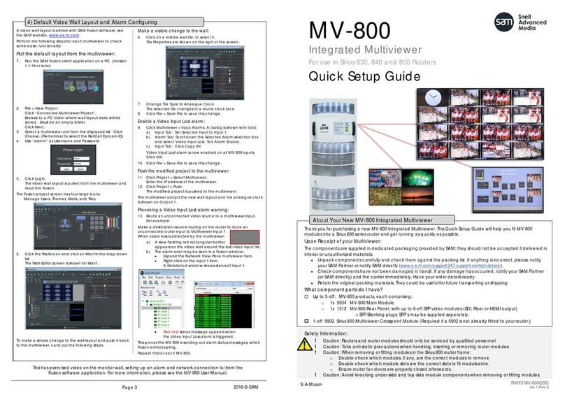
Thank you for purchasing a new MV-820 Multiviewer.
This Quick Setup Guide will help you get running as quickly as possible.
Upon Receipt of your MV-820 Multiviewer:
• The product is supplied in dedicated packaging provided by SAM;
it should not be accepted if delivered in inferior or unauthorized materials.
• Unpack the MV-820 product carefully and check components against the packing list.
If anything is incorrect, please notify your SAM Partner or notify SAM directly
(www.s-a-m.com/support/247-support-contact-details/).
• Check all components have not been damaged in transit.
If any damage has occurred, notify your SAM Partner (or SAM directly) and the carrier immediately.
Have your order details ready.
• Retain the original packing materials. They could be useful for future transporting or shipping.
MV-820
Multiviewer
Flexible Multi-head Displays
Quick Setup Guide
Safety Information:
Caution: MV-820 Multiviewer products should only be
serviced by qualified personnel.
Caution: Take anti-static precautions when handling the
product, or when inserting or removing any modules.
Caution: Ensure the MV-820 Multiviewer front door is
properly closed at all times.
Caution: The MV-820 can be equipped with optical
outputs, which contain low-power laser beams.
Warning: Do not look into an optical output. Laser
radiation can cause irreversible and permanent
damage of eyesight.
Warning: Do not look at the end of a fiber to see if light is
coming out. Use optical instrumentation.
Warning: Unused optical outputs should be covered, to
prevent direct exposure to the laser beam.
Warning: To reduce the risk of electric shock, do not
expose this equipment to water or moisture.
RMY3 MV-820QSG
MV-820 Quick Setup Guide
© 2017 SAM
MV-820 Quick Setup Guide
www.s-a-m.com
Fitting the MV-820 Multiviewer into a 19” Equipment Rack
The MV-820 is designed to be installed and used
in a standard 483mm (19 inch) equipment rack.
It requires a 2RU high rack-space.
MV-820 Unit Ventilation: see Figure 1.
•Caution: Always keep the MV-820 front
door closed. This ensures correct unit
ventilation and operation.
•Caution: Do not block the unit’s air intake
and exhaust holes.
•Caution: Ensure a minimum clearance at
the unit rear of 200 mm. This is essential.
•Warning: Use proper procedures to lift the
unit; it is heavy (14 kg, ~30.3 lb). Ask a
Health and Safety adviser for information
Rack-Mounting Instructions
1. Check the rack is rigid enough for the unit. Use a suitable rack tray to take the unit’s weight (see Table 1).
Note: The chassis rear will become heavier when cables are connected.
2. Position the MV-820 unit on the rack tray. Use the correct lifting procedures.
3. Open the front door by unscrewing the knurled door fasteners; then pull
the front door out approx. 2cm and then down. See Figure 2.
4. Secure the MV-820 Multiviewer chassis in the rack at each mounting
hole using 4-off M6 screws. See Figure 3 and Figure 4.
5. Close the front door by lifting it up and pushing it into the unit.
6. Secure the front door by tightening the knurled door fasteners.
Operating Environment 5ºC to 30 ºC ambient. 10 to 90% (non-condensing)
Weight 14 kg (~30.3lb)
Overall Chassis Dimensions: Width: 482.6 mm (~19 in.)
Depth: 604.8 mm (~23.8 in.)
Height: 87.0 mm (~3.42 in.)
Power Consumption 250 W
Table 1 MV-820 Specifications
Front Air Intake holes
Rear Air Exhaust holes
Side Air Exhaust
holes
Air Flow In
Figure 1 Ventilation of 2RU MV-820 Unit. Air Flow: Front-to-Rear
Knurled Front Door
Fasteners
Air Flow Out
Figure 2 Opening the Front Door
Out and
Down
Unit Rack
Mounting Holes
Figure 4 MV-820 Unit
Rack Mounting Holes
4-off M6 Screws
Rack Tray
Shelf
MV-820 Unit Chassis
Figure 3 Rack-Mounting MV-820 Unit
Connections
SFP modules are already fitted to the MV-820 Multiviewer unit. Rear connectors etc are shown in Figure 5.
Connect: a) Display Outputs 1 to 4 to monitor displays.
b) Analog reference signal to Ref In 1; terminate Ref Out 1 in 75 ohm.
c) Digital video signals to the Multiviewer Video Inputs.
d) A network cable to Network Interface Port 1 (1G Ethernet, “1G1”).
e) Connect IEC mains cords to the IEC inlets.
Powering Up MV-820 Multiviewer
1. Connect each mains cord to a separate branch mains circuits
employing separate service grounds.
2. The unit starts and boots up. Booting lasts 2 to 3 minutes. After
approx. 1 minute, a splash screen is shown on each Display
Output, see Figure 6.
3. When booting is complete, the splash screen goes away.
Initial MV-820 Configuration
1. Start SAM RollCall Control Panel (version 4.16.11 or later) on a laptop PC. Click the Build Network icon.
2. Enter MV-820 network interface port 1 (1G1) default IP address: 10.54.31.221. RollCall connects to MV-820.
3. Navigate to RollCall MV-820 Multiviewer System-Setup screen.
4. Set up Network Settings relevant for your house network (IP address, Subnet mask, etc).
5. In RollCall Settings, set up the Unit number (default = 01) and Domain ID (default = 100) for the MV-820.
Note: Unit number must be unique for each unit. Typically, Domain ID is the same for each MV-820.
Restart:
6. Click System Reset (in RollCall Control Panel System-Setup screen); then click Confirm.
A MV-820 System Reset is started.
While MV-820 reboots, a splash screen shows MV-820 unit’s IP address and other details, see Figure 6.
7. Disconnect the MV-820’s 1G1 port from the Laptop PC and connect the MV-820 to the house network.
Initial configuration for the MV-820 is done.
Default Video Wall
Each Display Output shows a 3x4 video tile-grid wall. Video Inputs 1 to 48 are shown across Display Outputs 1 to 4.
Figure 5 MV-820 Multiviewer Rear Connections and Indicators
Out 1: 123 Out 2: 13 14 15 Out 3: 25 26 27 Out 4: 37 38 39
4 5 6 16 17 18 28 29 30 40 41 42
7 8 9 19 20 21 31 32 33 43 44 45
10 11 12 22 23 24 34 35 36 46 47 48
Display Outputs 1 to 12:
6-off SFP Cages for Video SFP’s
(2x HD-BNC or 2xFiber) LTC & GPIO:
Female 26-way D
Network Interface Ports:
4-off SFP cages for
Ethernet RJ-45 SFP’s
[Port1, Port2, Port3, Port4
“1G1”, “1G2”, “10G3”, “10G4”]
Reference BNC’s:
2x Ref In & Ref-Out.
Unterminated.
Multiviewer Video Inputs 1 to 48:
(2x 24-off HD-BNC connectors)
SDI, HD-SDI, 3G-SDI PSU Status LEDs:
IEC
Mains
Inlets
Blue: Licensed and SFP fitted
Red: Licensed, No SFP fitted
Off: Unlicensed Output.
Output Status LED per Output
1 2 3 4......................11 12
Figure 6 MV-820 Booting Splash Screen
(Note: IP Address information shown)
Normal Operation
Standby
Warning
Fault
Green:
Flashing:
Flashing:
Yellow:
Page 2
Page 1

Other Snell Advanced Media Media Converter manuals

Snell Advanced Media MV-800 User manual

Snell Advanced Media

Snell Advanced Media MV-800 User manual

Snell Advanced Media IQUPC30 Operator's manual

Snell Advanced Media

Snell Advanced Media IQUPC30 Operator's manual

Snell Advanced Media IQDNC30 Operator's manual

Snell Advanced Media

Snell Advanced Media IQDNC30 Operator's manual

Snell Advanced Media MV-800 User manual

Snell Advanced Media

Snell Advanced Media MV-800 User manual

Snell Advanced Media LiveTouch Lite User manual

Snell Advanced Media

Snell Advanced Media LiveTouch Lite User manual

Snell Advanced Media KudosPro MC500 User manual

Snell Advanced Media

Snell Advanced Media KudosPro MC500 User manual

Snell Advanced Media KudosPro LC2000 User manual

Snell Advanced Media

Snell Advanced Media KudosPro LC2000 User manual

Snell Advanced Media KudosPro MC1000 User manual

Snell Advanced Media

Snell Advanced Media KudosPro MC1000 User manual

Snell Advanced Media Kudos Pro UHD1000 User manual

Snell Advanced Media

Snell Advanced Media Kudos Pro UHD1000 User manual

Snell Advanced Media MV-820 User manual

Snell Advanced Media

Snell Advanced Media MV-820 User manual

Snell Advanced Media IQUDC30 Operator's manual

Snell Advanced Media

Snell Advanced Media IQUDC30 Operator's manual

Popular Media Converter manuals by other brands

Datalogic AMT58-S-16x14 FBUS Series Mounting instructions

Datalogic

Datalogic AMT58-S-16x14 FBUS Series Mounting instructions

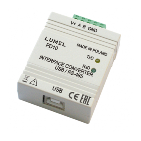
Lumel PD10 user manual

Lumel

Lumel PD10 user manual

Elettronica Santerno AMS90/1 Series Applications manual

Elettronica Santerno

Elettronica Santerno AMS90/1 Series Applications manual

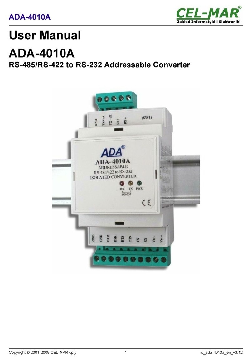
CEL-MAR ADA-4010A user manual

CEL-MAR

CEL-MAR ADA-4010A user manual

Kramer VP-409 user manual

Kramer

Kramer VP-409 user manual

Shinybow USA SB-3800 instruction manual

Shinybow USA

Shinybow USA SB-3800 instruction manual

TIE MIDI 1i1o-e user manual

TIE

TIE MIDI 1i1o-e user manual

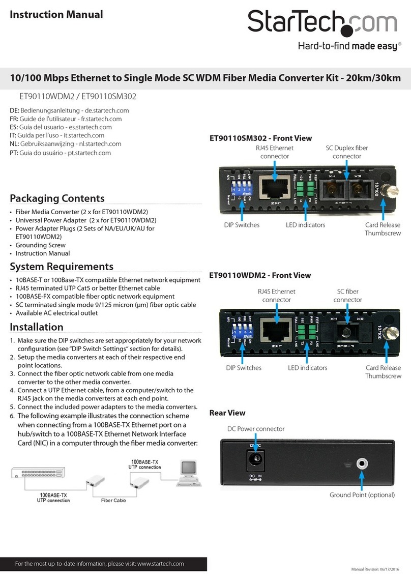
StarTech.com ET90110SM302 instruction manual

StarTech.com

StarTech.com ET90110SM302 instruction manual

Teryair SN 16 PG Operation & maintenance guide

Teryair

Teryair SN 16 PG Operation & maintenance guide

evertz SCRF Series quick start guide

evertz

evertz SCRF Series quick start guide

RGBlink VENUS X1 user manual

RGBlink

RGBlink VENUS X1 user manual

WEISS DAC204 operating manual

WEISS

WEISS DAC204 operating manual

HF Protoss-PE11 user manual

HF

HF Protoss-PE11 user manual

M-system 18JV instruction manual

M-system

M-system 18JV instruction manual

VAD DAC-10 user manual

VAD

VAD DAC-10 user manual

SMC Networks EZ Connect user guide

SMC Networks

SMC Networks EZ Connect user guide

PEAK COMMUNICATIONS P7001R Installation and operating handbook

PEAK COMMUNICATIONS

PEAK COMMUNICATIONS P7001R Installation and operating handbook

Allied Telesis AT-LMC100SC installation guide

Allied Telesis

Allied Telesis AT-LMC100SC installation guide

manuals.online logo
manuals.online logoBrands
  • About & Mission
  • Contact us
  • Privacy Policy
  • Terms and Conditions

Copyright 2025 Manuals.Online. All Rights Reserved.