Snell & Wilcox SHDFTRX0WQ2 User manual

SHDFTRX OPERATION
System HD Optical HD-SDI Transceiver
Operation Manual
SHDFTRX Version 1 Issue 5 180203 1
CONTENTS
INTRODUCTION TO THIS INSTALLATION
MANUAL................................................................ 2
SCOPE OF THIS OPERATION MANUAL ............4
MODULE DESCRIPTION ................................. 4
FEATURES ............................................................ 6
TECHNICAL PROFILE.......................................... 7
TRANSMITTER INPUT..................................... 7
Active Loop-through.....................................7
TRANSMITTER OUTPUTS ..............................7
RECEIVER INPUT............................................7
RECEIVER OUTPUTS ..................................... 7
SWITCHES, BOARD EDGE ............................. 7
INDICATOR LEDS............................................7
ROLLCALL....................................................8
OPTIONS..........................................................8
REAR INTERFACE CONNECTIONS.................... 9
REAR INTERFACE NOTATION GUIDE...........9
STANDARD AND WDM TRANSMITTER
INPUT .............................................................11
STANDARD AND WDM TRANSMITTER
ELECTRICAL LOOP-THROUGH ................... 11
STANDARD TRANSMITTER OUTPUTS .......12
OPTICAL HD-SDI OUTPUT – QUAD
OUTPUT OPTION .......................................... 12
OPTICAL HD-SDI OUTPUT – DUAL
OUTPUT OPTION .......................................... 12
OPTICAL HD-SDI OUTPUT – SINGLE
OUTPUT OPTION .......................................... 12
WDM TRANSMITTER INTERFACES.............13
STANDARD RECEIVER INPUT ..................... 13
STANDARD AND WDM RECEIVER
OUTPUTS.......................................................13
WDM COMBINED RECEIVER INPUT AND
OPTICAL TRANSMITTER OUTPUT ..............14
ROLLCALL MENU SYSTEM ..............................15
ROLLCALL MONITORING FEATURES .........16

SHDFTRX OPERATION
SHDFTRX Version 1 Issue 5 180203 2
Introduction to this Operation Manual
This manual covers the operation and use of the modules described below.
WARNING…
THE FRONT PANEL OF THE UNIT MUST NOT BE
OPENED BY THE OPERATOR. ACCESS IS ONLY
PERMITTED TO FULLY QUALIFIED
INSTALLATION ENGINEERS.
System HD Modules must only be installed and/or replaced by qualified service personnel, with reference to
the System HD Installation guide. Refer all installation and servicing to qualified personnel only.
All laser transmitters used in this product are Class
1 in accordance
with EN60825-1 as well as 21CFR 1040.10 and
1040.11
1. Laser light can be damaging to the eyes.
Optical fibres and Uniters should be handled with
great care.
2. System HD Modules which incorporate Fibre
Optic elements, are designed for use with Class 1
laser systems only. Ensure that all inputs do NOT
exceed Class 1 as doing so will impair the safety
of the system and may result in damage to the
equipment.
3. Active fibres should not be handled unless
their source can be positively identified as not
exceeding Class 1 limits.

SHDFTRX OPERATION
SHDFTRX Version 1 Issue 5 180203 3
Manufacturers Notice
Copyright protection claimed includes all forms and matters of copyrightable material and information now
allowed by statutory or judicial law or hereinafter granted, including without limitation, material generated from
the software programs which are displayed on the screen such as icons, screen display looks etc.
Reproduction or disassembly of embedded computer programs or algorithms is prohibited.
No part of this publication may be transmitted or reproduced in any form or by any means, electronic or
mechanical, including photocopy, recording or any information storage and retrieval system, without
permission being granted, in writing, by the publishers or their authorised agents.
Important Notice
No responsibility is taken by the manufacturer or supplier for any non-compliance to EMC standards due to
incorrect installation.
Information in this manual and software are subject to change without notice and does not represent a
commitment on the part of Snell & Wilcox Ltd. The software described in this manual is furnished under a
licence agreement and may not be reproduced or copied in any manner without prior agreement with Snell &
Wilcox Ltd. or their authorised agents.

SHDFTRX OPERATION
SHDFTRX Version 1 Issue 5 180203 4
Scope of this Operation Manual
This is the operation manual for the System HD Fibre Optic Transceiver module. It covers the modules ordered
under the following codes :
SHDFTRX0WQ4 – Standard Transceiver with 4 optical outputs from the Transmitter
SHDFTRX0WQ2 – Standard Transceiver with 2 optical outputs from the Transmitter
SHDFTRX0WQ0 – Standard Transceiver with a single optical output from the Transmitter
SHDFTRX0WQC – WDM Transceiver with a single optical interface (Use with SHDFTRX6WQD)
SHDFTRX6WQD – WDM Transceiver with a single optical interface (Use with SHDFTRX0WQC)
SHDFTRX0WQ4 : Rear Panel View
SHDFTRX0WQ2 and SHDFTRX0WQ1 : Rear Panel View
SHDFTRX0WQC and SHDFTRX6WQD : Rear Panel View
Module Description
The Optical HD-SDI Transceiver can convert an
electrical HD-SDI bitstream to an optical HD-SDI
bitstream while simultaneously converting a
separate optical HD-SDI bitstream into an electrical
HD-SDI bitstream. With the ‘standard’ interface
card fitted (rear view shown above), the optical
input path provides four identical electrical HD-SDI
outputs and the electrical HD-SDI input channel
can provide up to four identical optical HD-SDI
outputs.
The electrical high definition serial digital (HD-SDI)
bitstream interfaces are via 75ΩBNC connectors
on the backpanel of the rear interface card. The
optical outputs are via the SMPTE292M
recommended SC/PC singlemode fibre optic
connectors. The SC/PC connector is robust and
easy to use, a simple snap-fit enables a reliable
connection to be made in a matter of seconds.
Connected to the single output of the laser
transmitter is an optional passive optical splitting

SHDFTRX OPERATION
SHDFTRX Version 1 Issue 5 180203 5
device providing up to four identical optical outputs.
The options for this split are either a four way
splitter, a two way splitter, or a single output.
Selection between these options depends on the
rear interface fitted and does not affect the main
board part of the module. Even in the case of the
four way splitter the optical power available from
each of these outputs is sufficient to transmit a HD-
SDI signal over distances greater than 20km.
A re-clocked active loop-through of the electrical
HD-SDI bitstream input is available from a BNC
connector for monitoring purposes. Three optical
power options, including two wavelength variants
are available as laser options. The different
wavelengths are provided for Wavelength Division
Multiplexing (WDM) options on this board.
The receiver section of the transceiver main board
accepts a single optical high definition serial digital
(HD-SDI) bitstream input via a SC/PC singlemode
fibre optic connector. The re-clocked electrical HD-
SDI signal output from the receiver is split to
provide four identical coaxial HD-SDI outputs for
the user at the backpanel of the interface card.
When used in conjunction with a System HD
optical transmitter (and depending on the fibre
interconnect used) the sensitivity of the optical
receiver is sufficient to recover a signal transmitted
from up to 20km away. The receiver device is
capable of recovering wavelengths between 1.2-
1.6µm making it suitable for wavelength division
multiplexing (WDM) applications.
By using the ‘WDM’ interface card, the transceiver
card allows simultaneous transmission/reception of
two different wavelengths, 1.3µm and 1.5µm.
LEDs mounted at the front of the main board allow
monitoring of the receiver performance. More
detailed performance information can be obtained
via the RollCall interface.
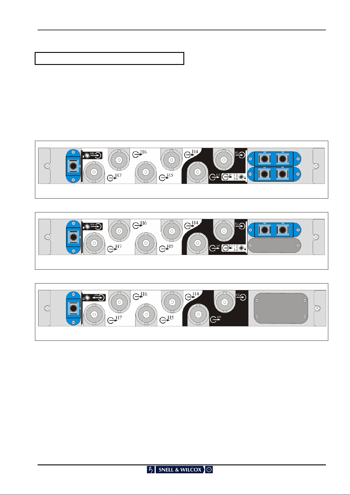
The ‘standard’ rear interface card option offers four
optical outputs for the transmitter section of the
transceiver. However, depending on the
application, two or single output options are also
available as well as a ‘WDM’ interface card.
It is recommended that the System HD Order Code
of the board and interface card combination is
recorded in this manual on the next page using the
table on this page for your own reference.
This will allow easy identification of the laser option
chosen and the type of interface card selected
when referring to this manual at a later date.
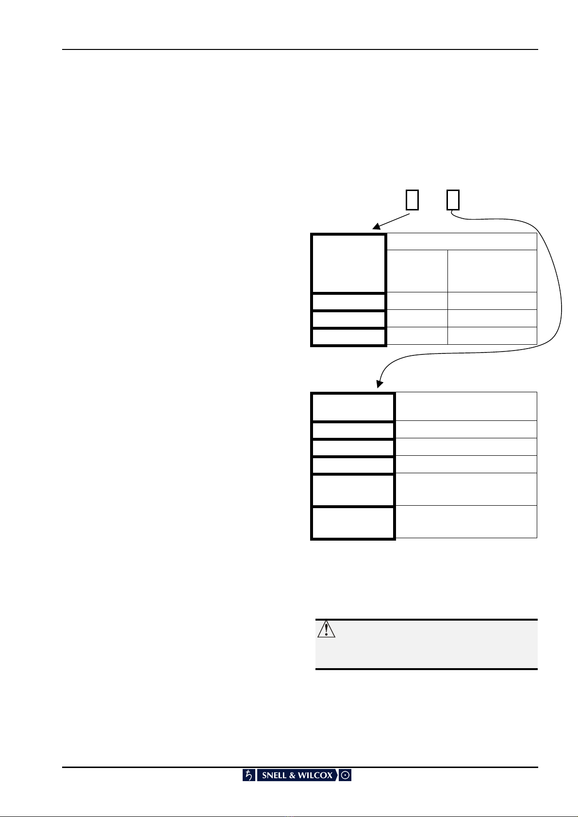
Quick guide to order codes:
SHDFTRX XW Q X
Laser properties
Laser device
option code Wavelength
λ(µm)
Laser output
power before split
Po (dBm)
01.3 -2
11.3 0
61.5 0
Interface card
option code
Interface card supplied with
main transmitter board
41x4 splitter on Tx out
21x2 splitter on Tx out
0Patch cord (no split) on Tx out
A‘WDM’ Mux fitted: 1.3µm OUT
1.5µm IN
B‘WDM’ Mux fitted: 1.5µm OUT
1.3µm IN
Codes other than those listed refer to custom laser
options. Additional information should have been
delivered with the module.
NOTE…
All the laser transmitters used on ‘System HD’
optical boards are CLASS 1 LASER PRODUCTS.
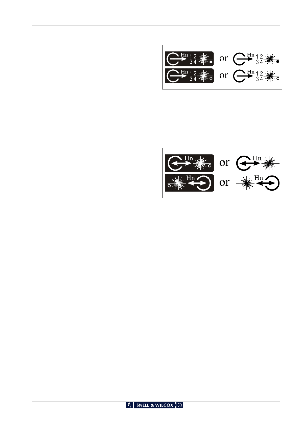
Laser
options
Interface
o
p
tions

SHDFTRX OPERATION
SHDFTRX Version 1 Issue 5 180203 6
Features
Optical transmission and recovery capability on
single board
SMPTE 292M 1.485Gbit/s HD-SDI data rates
supported
SMPTE 292M recommended SC/PC
singlemode user interface connectors
Four coaxial outputs from single optical input
Four optical outputs from single coaxial input
Transmission distances up to 20km
Two optical output wavelengths
(1300/1550nm) available for laser transmitter
Receiver wavelength input range 1200-
1600nm
WDM bi-directional capability
Optical to optical reclocking capability
Optical data transport offering:
EMI immunity
No earth loops
Small, lightweight, flexible cabling
Easy to locate and repair cable breaks
Alarm functions for poor quality input signals
and device malfunction
Stand-alone or RollCall operation
Incoming signal analysis available as an
option, it includes:
CRC status
Line standard
Frame rate
Error rate
Note:
RollCallTM enabled for remote system control &
monitoring.

SHDFTRX OPERATION
SHDFTRX Version 1 Issue 5 180203 7
Technical Profile
TRANSMITTER INPUT
Electrical 1.485GBit/s HD-SDI
Connector Format BNC 75ohm panel jack
Input Cable Length >100m
Peak-to-peak
signal amplitude
800mV ±10%
D.C. offset 0V ±0.5V
Rise time (20-80%)
Fall time (20-80%)
Difference
<270ps
<270ps
≤100ps
Return loss >15dB
Active Loop-through
Electrical 1.485GBit/s HD-SDI
Connector Format BNC 75ohm panel jack
Peak-to-peak
signal amplitude
800mV ±10%
D.C. offset 0V ±0.5V
Rise time (20-80%)
Fall time (20-80%)
Difference
< 270ps
< 270ps
≤100ps
Return loss >15dB
TRANSMITTER OUTPUTS
Optical 1.485Gbit/s HD-SDI
Connector Format SC/PC singlemode panel
uniter
Outputs 4 (other split options
available)
Wavelength 1300nm±30nm
(1550nm optional)
Spectral width
(FWHM)
<1nm
Output power
(after 4 way split)
Low power 1.3µm ~ -10dBm
High power 1.3µm ~ -8dBm
High power 1.55µm ~ -8dBm
Extinction ratio > 5:1
RECEIVER INPUT
Optical 1.485GBit/s HD-SDI
Connector Format SC/PC singlemode panel
uniter
Input wavelength
range
Min. 1200nm
Max. 1600nm
Optical power input
range
Max. <-3dBm
Min. >-23dBm
Detector damage
threshold
+10dBm
RECEIVER OUTPUTS
Electrical 1.485Gbit/s HD-SDI
Connector Format BNC 75ohm panel jack
Outputs 4
Output Cable
Length
>100m
Peak-to-peak
signal amplitude
800mV ±10%
D.C. offset 0V ±0.5V
Rise time (20-80%)
Fall time (20-80%)
Difference
< 270ps
< 270ps
≤100ps
Return loss >15dB
The shaded functions are not available to the
Operator
SWITCHES, Board Edge
Tx1 disable Disables the laser
INDICATOR LEDS
Transmitter
Power Power supplies valid
Fault Board fault
CPU Valid CPU activity
Dis Laser output disabled
Ihi Laser current high
PLL lock Output locked to input
standard
CRC status Data error
Line Indicates line standard
Frame Indicates frame rate
Prog/Int Indicates progressive or
interlaced frames
Receiver
Pin Input of sufficient power
present
PLL Lock Output locked to input
standard
CRC Error Data error
Line Indicates line rate
Frame Indicates frame rate
Prog/Int Indicates progressive or
interlaced frames

SHDFTRX OPERATION
SHDFTRX Version 1 Issue 5 180203 8
RollCall™
RollCall control
options:
RollCall monitoring
options:
General alarm
Supply voltage levels
Board temperature
For both data channels
CRC status
Line standard
Frame rate
Error rate
WEIGHT <850gm (Main Board plus
Interface Board)
POWER CODE 2
OPTIONS See page 5 for options
Notes…
1. The transmitter section of the transceiver
can have a different laser type depending
on its intended application. Refer to the
laser device option code on page 4 to
identify what laser is fitted to the board.
2. Various splitter options are available for the
transmitter section as well as a WDM
option. Refer to the interface card option
code on page 4 to identify what interface
card has been supplied with the main
transmitter board.
3. Codes in the ORDER NUMBER other than
those listed below will refer to custom
laser/interface card options. Additional
information should have been delivered
with the cards. If further information is
required please contact the factory.

SHDFTRX OPERATION
SHDFTRX Version 1 Issue 5 180203 9
Rear Interface Connections
Rear Interface Notation Guide
Electrical HD-SDI Input
A High Definition Serial Digital electrical input
though a 75ΩBNC connector is denoted in the way
shown opposite. The “ H ” denotes the High
Definition element and the “ n” is the connection
number for that particular rear interface.
Electrical HD-SDI Output
A High Definition Serial Digital electrical output
though a 75ΩBNC connector is denoted in the way
shown opposite. The “ H ” denotes the High
Definition element and the “ n” is the connection
number for that particular rear interface.
Optical HD-SDI Input
A High Definition Serial Digital optical input though
a SC/PC single mode panel uniter is denoted in the
way shown opposite. The “ H ” denotes the High
Definition element and the “ n” is the connection
number for that particular rear interface. The solid
“dot” indicates that only a single wavelength can be
presented through the connector. A hollow circle
indicates multiple wavelengths are permissible.
Single Optical HD-SDI Output
A single High Definition Serial Digital optical output
though one SC/PC single mode panel uniter is
denoted in the way shown opposite. The “ H ”
denotes the High Definition element and the “ n” is
the connection number for that particular rear
interface. The solid “dot” indicates that only a single
wavelength can be presented through the
connector. A hollow circle indicates multiple
wavelengths are permissible

SHDFTRX OPERATION
SHDFTRX Version 1 Issue 5 180203 10
Multiple Optical HD-SDI Outputs
Multiple High Definition Serial Digital optical
outputs though two or four SC/PC single mode
panel uniters are denoted in the way shown
opposite. The numbers 1 to 4 are arranged to
indicate the individual element within the multiple
output connector. The “ H ” denotes the High
Definition element and the “ n” is the overall
connection number for that particular rear interface.
The solid “dot” indicates that only a single
wavelength will be output through the connectors.
A hollow circle indicates multiple wavelengths are
present
Bi-directional Optical HD-SD I I/O
Bi-directional High Definition Serial Digital optical
input and output though a single connector using
different laser wavelengths (WDM). The “ H ”
denotes the High Definition element and the “ n” is
the overall connection number for that particular
rear interface. This intrinsically requires a hollow
circle to indicate multiple wavelengths are
permissible through this connector.

SHDFTRX OPERATION
SHDFTRX Version 1 Issue 5 180203 11
Standard and WDM
Transmitter Input
Electrical HD-SDI
Used On : SHDFTRX0WQ4
SHDFTRX0WQ2
SHDFTRX0WQ0
SHDFTRX0WQC
SHDFTRX6WQD
The high definition serial digital electrical input for
the laser transmitter is connected to a 75ΩBNC
connector. This connector is shown opposite and
is labelled H2 on the rear panel.
Standard and WDM
Transmitter Electrical
Loop-Through
Electrical HD-SDI
Used On : SHDFTRX0WQ4
SHDFTRX0WQ2
SHDFTRX0WQ0
SHDFTRX0WQC
SHDFTRX6WQD
An equalised and reclocked version of the high
definition serial digital electrical input for the
transmitter is available as an active loop-through
from a 75ΩBNC connector. This connector is
shown opposite and is labelled H3 on the rear
panel.
1. Laser light can be damaging to the eyes.
Optical fibres and Uniters should be
handled with great care.
2. System HD Modules which incorporate
Fibre Optic elements, are designed for use
with Class 1 laser systems only. Ensure
that all inputs do NOT exceed Class 1 as
doing so will impair the safety of the
system and may result in damage to the
equipment.
3. Active fibres should not be handled unless
their source can be positively identified as
not exceeding Class 1 limits.
Notes…
1. Optical uniters have plastic covers to prevent
the ingress of dust. These covers should only
be removed when connecting optical fibres. A
uniter should never be left open without a
cover or a fibre connector
2. The ends of optical fibres should be cleaned
with a liquid fibre cleaner, using a cotton bud,
to ensure that there is no dust present, before
they are plugged in (the uniter is polarised).
3. Observe the warning about not viewing live
optical sources.

SHDFTRX OPERATION
SHDFTRX Version 1 Issue 5 180203 12
Standard Transmitter Outputs
Optical HD-SDI Output – Quad Output Option
Used On : SHDFTRX0WQ4
The high definition serial digital optical outputs are
provided via a pair of dual SC/PC single mode
panel mounted uniters. The overall connection is
labelled as H1 on the rear panel as shown
opposite. The four optical outputs are denoted as
1, 2, 3, and 4 and arranged as shown in the
diagram. All four outputs produce almost identical
levels of optical power and identical digital
bitstreams. These are single optical wavelength
outputs.
Do not remove the covers from the uniters until a
fibre connection is ready to be inserted.
Optical HD-SDI Output – Dual Output Option
Used On : SHDFTRX0WQ2
The high definition serial digital optical outputs are
provided via a dual PC/SC single mode panel
mounted uniter set. The overall connection is
labelled as H1 on the rear panel as shown
opposite. The two optical outputs are denoted as 1,
and 2. The rear label mentions connections 3, and
4 as well, but these are not present in this case.
The connectors are arranged as shown in the
diagram. Both outputs produce almost identical
levels of optical power and identical digital
bitstreams. These are single optical wavelength
outputs.
Do not remove the covers from the uniters until a
fibre connection is ready to be inserted
Optical HD-SDI Output – Single Output Option
Used On : SHDFTRX0WQ0
The high definition serial digital optical output is
provided from one side of a dual SC/PC single
mode panel mounted uniter. The overall connection
is labelled as H1 on the rear panel as shown
opposite. The optical output is denoted as
connection 1. The rear label mentions 2, 3, and 4
as well but these are not present in this case. The
connector is arranged as shown in the diagram.
This is a single optical wavelength output.
Do not remove the cover from the uniter until a
fibre connection is ready to be inserted

SHDFTRX OPERATION
SHDFTRX Version 1 Issue 5 180203 13
WDM Transmitter Interfaces
Electrical HD-SDI - Only
Used On : SHDFTRX0WQC
SHDFTRX6WQD
The high definition serial digital electrical input for
the WDM laser transmitter is the same as for the
standard transceiver options. It is shown opposite
labelled as H2 on the rear panel. In the same
manner the electrical loop through of the
transmitter input is also the same as for the non-
WDM options and is shown in the diagram opposite
labelled as H3. However there is no independent
access to the optical output from the transmitter
from the rear panel in the WDM case. The area
used for the optical transmitter interfaces are
shown in the diagram opposite as blanked off.
Standard Receiver Input
Optical HD-SDI Input
Used On : SHDFTRX0WQ4
SHDFTRX0WQ2
SHDFTRX0WQ0
The high definition serial digital optical input is
connected to an SC/PC single mode panel uniter.
This connector is shown opposite and is labelled
H8 on the rear panel. This is a single optical
wavelength interface in these cases.
Standard and WDM
Receiver Outputs
Electrical HD-SDI : Quad Outputs
Used On : SHDFTRX0WQ4
SHDFTRX0WQ2
SHDFTRX0WQ0
SHDFTRX0WQC
SHDFTRX6WQD
The four high definition serial digital electrical
outputs are available from four 75ΩBNC
connectors. The same digital bitstream is provided
by all four connectors. This bitstream is a reclocked
version of the optical signal provided to the optical
receiver. These electrical outputs are labelled as
H4, H5, H6, and H7 on the rear panel as illustrated
in the diagram opposite.

SHDFTRX OPERATION
SHDFTRX Version 1 Issue 5 180203 14
WDM Combined
Optical Receiver Input and Optical
Transmitter Output
Optical HD-SDI Input and Output
Used On : SHDFTRX0WQC
SHDFTRX6WQD
For the WDM options of this module the high
definition serial digital optical input is combined with
the optical output from the transmitter. This is
achieved using different optical wavelengths for the
transmit and receive paths. Due to this only a
single SC/PC single mode panel uniter is required
to connect to both the transmitter and the receiver.
This connector is shown opposite and is labelled
H8 on the rear panel. This is a dual optical
wavelength interface in these cases.

SHDFTRX OPERATION
SHDFTRX Version 1 Issue 5 180203 15
RollCall Menu System
When a System HD Control and Monitor board is
fitted in the enclosure a range of monitoring
information is available to RollCall
External Monitoring Description
General alarm Input power fault or
overcurrent trip or
system failure
Supply voltage levels Actual voltage levels
Board temperature Actual board
temperature
For Both Data Channels
Bit error rate Error rate over defined
time period

SHDFTRX OPERATION
SHDFTRX Version 1 Issue 5 180203 16
Rollcall Monitoring Features
Module Infrastructure:
General Alarm
Supply Voltage Levels
Board Temperature
Incoming Signal analysis:
Input Status
Line Standard
Frame Type
Frame Rate
CRC Error analysis:
CRC Error Count
CRC Error Total
CRC Reset
Bias/EQ – The value in this field is a guide to
the strength of equalisation that is being
applied to the input signal for longer cable
runs. The lower the value, the less equalisation
is being employed. It is intended as a guide for
troubleshooting the system. It should be noted
that when an equalisation of 100% is shown, it
doesn’t necessarily mean that the maximum
input cable length has been reached. As soon
as CRC errors are being reported then the
input cable length should be decreased until an
error free signal can be received.
Laser Case Temperature / Bias (Degrees °C) –
The case temperature is an indication of how
much Laser Drive Strength is being applied i.e.
Laser Bias current. As the laser becomes
older, the drive strength will be increased
which will therefore cause its case temperature
to rise.
Received Laser Power (dBm) – This is the amount
of Laser power being received. It indicates how
much attenuation has been applied to the signal.

SHDFTRX OPERATION
SHDFTRX Version 1 Issue 5 180203 17
Manual Revision Record
Date Version No. Issue No. Change Comments
16/06/01 1 1 Revised draft document Issued
22/08/01 1 2 Edited current feature list Only
states features that are present in
current release A1.0.000
New issue released
030402 1 3 New monitoring features added New issue released
100203 1 4 Corrections New issue released
180203 1 5 To spec New issue released
This manual suits for next models
6
Table of contents
Other Snell & Wilcox Transceiver manuals