Snell MV-32 User manual

snellgroup.com
User Manual
MV-32/64 Multiviewer
Enables up to 32 or 64 channels of video to be
viewed on a single display device

MV-32/64 Multiviewer www.snellgroup.com
Issue 1 Rev 11 Page 2 © 2014 Snell Limited

MV-32/64 Multiviewer www.snellgroup.com Contents
Issue 1 Rev 11 Page 3 © 2014 Snell Limited
Contents
1. Information and Notices . . . . . . . . . . . . . . . . . . . . . . . . . . . . . . . . . . . . . . . . . . . . . . 7
1.1 Customer Support . . . . . . . . . . . . . . . . . . . . . . . . . . . . . . . . . . . . . . . . . . . . . . . . . 7
1.2 Copyright and Disclaimer . . . . . . . . . . . . . . . . . . . . . . . . . . . . . . . . . . . . . . . . . . . 7
1.3 Safety Standards . . . . . . . . . . . . . . . . . . . . . . . . . . . . . . . . . . . . . . . . . . . . . . . . . . 8
2. Introduction. . . . . . . . . . . . . . . . . . . . . . . . . . . . . . . . . . . . . . . . . . . . . . . . . . . . . . . . . 9
2.1 System concept. . . . . . . . . . . . . . . . . . . . . . . . . . . . . . . . . . . . . . . . . . . . . . . . . . . 9
2.1.1 Video Input Card types. . . . . . . . . . . . . . . . . . . . . . . . . . . . . . . . . . . . . . 10
2.1.2 Audio Input Card Types . . . . . . . . . . . . . . . . . . . . . . . . . . . . . . . . . . . . . .11
2.1.3 Audio Output Card Types. . . . . . . . . . . . . . . . . . . . . . . . . . . . . . . . . . . . .11
2.1.4 Card Type/Firmware Version Compatibility . . . . . . . . . . . . . . . . . . . . . . .11
2.2 Features and benefits . . . . . . . . . . . . . . . . . . . . . . . . . . . . . . . . . . . . . . . . . . . . . 12
2.2.1 Powerful alarms . . . . . . . . . . . . . . . . . . . . . . . . . . . . . . . . . . . . . . . . . . . 13
2.2.2 Captions and UMDs . . . . . . . . . . . . . . . . . . . . . . . . . . . . . . . . . . . . . . . . 13
2.2.3 Using bitmaps . . . . . . . . . . . . . . . . . . . . . . . . . . . . . . . . . . . . . . . . . . . . 13
2.2.4 Keeping time . . . . . . . . . . . . . . . . . . . . . . . . . . . . . . . . . . . . . . . . . . . . . 13
2.2.5 Genlocking . . . . . . . . . . . . . . . . . . . . . . . . . . . . . . . . . . . . . . . . . . . . . . . 14
2.2.6 Using GPI I/O . . . . . . . . . . . . . . . . . . . . . . . . . . . . . . . . . . . . . . . . . . . . . 14
2.2.7 Bargraph scales . . . . . . . . . . . . . . . . . . . . . . . . . . . . . . . . . . . . . . . . . . . 14
3. Installation . . . . . . . . . . . . . . . . . . . . . . . . . . . . . . . . . . . . . . . . . . . . . . . . . . . . . . . . 15
3.1 Power and fuses . . . . . . . . . . . . . . . . . . . . . . . . . . . . . . . . . . . . . . . . . . . . . . . . . 16
3.2 Health and safety considerations . . . . . . . . . . . . . . . . . . . . . . . . . . . . . . . . . . . . 16
3.2.1 Disposal . . . . . . . . . . . . . . . . . . . . . . . . . . . . . . . . . . . . . . . . . . . . . . . . . 16
3.2.2 FCC Compliance . . . . . . . . . . . . . . . . . . . . . . . . . . . . . . . . . . . . . . . . . . 16
3.3 Connector I/O . . . . . . . . . . . . . . . . . . . . . . . . . . . . . . . . . . . . . . . . . . . . . . . . . . . 17
3.3.1 Example: MV-32 Dual Multiviewer Rear Panel Connections . . . . . . . . . 17
3.3.2 Example: MV-64 Multiviewer Rear Panel Connections . . . . . . . . . . . . . 18
3.4 Input card configurations . . . . . . . . . . . . . . . . . . . . . . . . . . . . . . . . . . . . . . . . . . . 18
3.4.1 Video Inputs . . . . . . . . . . . . . . . . . . . . . . . . . . . . . . . . . . . . . . . . . . . . . . 20
3.4.2 Video Outputs. . . . . . . . . . . . . . . . . . . . . . . . . . . . . . . . . . . . . . . . . . . . . 20
3.4.3 Audio I/O . . . . . . . . . . . . . . . . . . . . . . . . . . . . . . . . . . . . . . . . . . . . . . . . 20
3.5 Serial port assignments. . . . . . . . . . . . . . . . . . . . . . . . . . . . . . . . . . . . . . . . . . . . 21
3.6 Audio I/O connector. . . . . . . . . . . . . . . . . . . . . . . . . . . . . . . . . . . . . . . . . . . . . . . 22
3.7 Backup Power Supply . . . . . . . . . . . . . . . . . . . . . . . . . . . . . . . . . . . . . . . . . . . . . 23
3.7.1 25 Way D-Type CN500 Pin Assignment . . . . . . . . . . . . . . . . . . . . . . . . 24
3.8 Thermal Protection . . . . . . . . . . . . . . . . . . . . . . . . . . . . . . . . . . . . . . . . . . . . . . . 26

MV-32/64 Multiviewer www.snellgroup.com Contents
Issue 1 Rev 11 Page 4 © 2014 Snell Limited
4. Operation . . . . . . . . . . . . . . . . . . . . . . . . . . . . . . . . . . . . . . . . . . . . . . . . . . . . . . . . . 27
4.1 Initial setup . . . . . . . . . . . . . . . . . . . . . . . . . . . . . . . . . . . . . . . . . . . . . . . . . . . . . 27
4.1.1 Network settings. . . . . . . . . . . . . . . . . . . . . . . . . . . . . . . . . . . . . . . . . . . 28
4.1.2 Keyboard Operation . . . . . . . . . . . . . . . . . . . . . . . . . . . . . . . . . . . . . . . . 28
4.2 Using the web interface. . . . . . . . . . . . . . . . . . . . . . . . . . . . . . . . . . . . . . . . . . . . 29
4.2.1 Object and Source Explorer . . . . . . . . . . . . . . . . . . . . . . . . . . . . . . . . . . 32
4.2.2 Navigating the User Interface. . . . . . . . . . . . . . . . . . . . . . . . . . . . . . . . . 33
4.3 Module Menu. . . . . . . . . . . . . . . . . . . . . . . . . . . . . . . . . . . . . . . . . . . . . . . . . . . . 33
4.4 Setup Audio Meter Properties . . . . . . . . . . . . . . . . . . . . . . . . . . . . . . . . . . . . . . . 34
4.5 Set Time . . . . . . . . . . . . . . . . . . . . . . . . . . . . . . . . . . . . . . . . . . . . . . . . . . . . . . . 35
4.6 Layout Menu . . . . . . . . . . . . . . . . . . . . . . . . . . . . . . . . . . . . . . . . . . . . . . . . . . . . 36
4.6.1 Layout Properties . . . . . . . . . . . . . . . . . . . . . . . . . . . . . . . . . . . . . . . . . . 37
4.7 Group Menu . . . . . . . . . . . . . . . . . . . . . . . . . . . . . . . . . . . . . . . . . . . . . . . . . . . . 37
4.8 Object Menu . . . . . . . . . . . . . . . . . . . . . . . . . . . . . . . . . . . . . . . . . . . . . . . . . . . . 38
4.9 Grid Menu . . . . . . . . . . . . . . . . . . . . . . . . . . . . . . . . . . . . . . . . . . . . . . . . . . . . . . 39
4.10 Help Menu . . . . . . . . . . . . . . . . . . . . . . . . . . . . . . . . . . . . . . . . . . . . . . . . . . . . . 39
4.10.1 About . . . . . . . . . . . . . . . . . . . . . . . . . . . . . . . . . . . . . . . . . . . . . . . . . . 39
4.11 Module Properties . . . . . . . . . . . . . . . . . . . . . . . . . . . . . . . . . . . . . . . . . . . . . . . 40
4.11.1 Boards Tab . . . . . . . . . . . . . . . . . . . . . . . . . . . . . . . . . . . . . . . . . . . . . . 40
4.11.2 Screen Tab . . . . . . . . . . . . . . . . . . . . . . . . . . . . . . . . . . . . . . . . . . . . . . 41
4.11.3 Sources Tab . . . . . . . . . . . . . . . . . . . . . . . . . . . . . . . . . . . . . . . . . . . . . 42
4.11.4 Audio Monitor Outputs Tab . . . . . . . . . . . . . . . . . . . . . . . . . . . . . . . . . . 43
4.11.5 External Audio Outputs Tab . . . . . . . . . . . . . . . . . . . . . . . . . . . . . . . . . 43
4.11.6 GPIs Tab - GPO Alarms Sub Tab . . . . . . . . . . . . . . . . . . . . . . . . . . . . . 44
4.11.7 GPI Inputs Tab . . . . . . . . . . . . . . . . . . . . . . . . . . . . . . . . . . . . . . . . . . . 45
4.11.8 Network Tab . . . . . . . . . . . . . . . . . . . . . . . . . . . . . . . . . . . . . . . . . . . . . 46
4.11.9 Data-xx Tab . . . . . . . . . . . . . . . . . . . . . . . . . . . . . . . . . . . . . . . . . . . . . 46
4.11.10 Protocols - Serial Ports Tab . . . . . . . . . . . . . . . . . . . . . . . . . . . . . . . . 47
4.11.11 Protocols - Snell Router Network Tab. . . . . . . . . . . . . . . . . . . . . . . . . 49
4.12 Source Properties - Audio Tab . . . . . . . . . . . . . . . . . . . . . . . . . . . . . . . . . . . . . 52
4.13 Source Properties - Alarm Tab . . . . . . . . . . . . . . . . . . . . . . . . . . . . . . . . . . . . . 53
4.14 Source Properties - Copy Tab . . . . . . . . . . . . . . . . . . . . . . . . . . . . . . . . . . . . . . 54
4.15 External Audio Source Properties . . . . . . . . . . . . . . . . . . . . . . . . . . . . . . . . . . . 55
4.16 Edit Object Window . . . . . . . . . . . . . . . . . . . . . . . . . . . . . . . . . . . . . . . . . . . . . . 56
4.16.1 Edit Object - Type Tab . . . . . . . . . . . . . . . . . . . . . . . . . . . . . . . . . . . . . 56
4.16.2 Edit Object - Border tab . . . . . . . . . . . . . . . . . . . . . . . . . . . . . . . . . . . . 58
4.16.3 Edit Object - Parent Tab . . . . . . . . . . . . . . . . . . . . . . . . . . . . . . . . . . . . 59
4.16.4 Edit Object - UMD Tab . . . . . . . . . . . . . . . . . . . . . . . . . . . . . . . . . . . . . 60
4.16.5 Properties Tab . . . . . . . . . . . . . . . . . . . . . . . . . . . . . . . . . . . . . . . . . . . 61
5. Connection to Other Equipment. . . . . . . . . . . . . . . . . . . . . . . . . . . . . . . . . . . . . . . 81
5.1 Interfaces. . . . . . . . . . . . . . . . . . . . . . . . . . . . . . . . . . . . . . . . . . . . . . . . . . . . . . . 81
5.1.1 D-sub 9 serial interface, RS232/RS422 . . . . . . . . . . . . . . . . . . . . . . . . . 81
5.1.2 Global GPI Input/Output Connector . . . . . . . . . . . . . . . . . . . . . . . . . . . . 82
5.1.3 Video card GPI Input/Output pin assignments . . . . . . . . . . . . . . . . . . . . 84
5.1.4 Analog Audio Input/Output (Connector 1) Channels 1 to 16 . . . . . . . . . 84
5.1.5 Analog Audio Input/Output (Connector 2) Channels 17 to 32 . . . . . . . . 85
5.1.6 AES/EBU Audio input/output Connector 44 Pole Female . . . . . . . . . . . 85
5.1.7 Analog Monitor Out Connector D-sub 25 Male . . . . . . . . . . . . . . . . . . . 86
5.2 Configuring the MV-32/MV-64 for TSL UMD Protocol . . . . . . . . . . . . . . . . . . . . . 86
5.3 Example for setting up a GPI input to use as a Tally. . . . . . . . . . . . . . . . . . . . . . 88
5.4 Example Interfacing with a Kahuna 360 or Kahuna 360 Compact . . . . . . . . . . . 90
5.4.1 Connect the Kahuna 360 Mainframe to the Multiviewer . . . . . . . . . . . . 90
5.4.2 Setup the Kahuna 360 Protocol . . . . . . . . . . . . . . . . . . . . . . . . . . . . . . . 92
5.4.3 Kahuna 360 Peripherals Setup . . . . . . . . . . . . . . . . . . . . . . . . . . . . . . . 93
5.4.4 Multiviewer Setup. . . . . . . . . . . . . . . . . . . . . . . . . . . . . . . . . . . . . . . . . . 94
5.5 Connecting the Multiviewer to a Nucleus or Nebula Controller . . . . . . . . . . . . . . 98
5.5.1 RS 422 Connection . . . . . . . . . . . . . . . . . . . . . . . . . . . . . . . . . . . . . . . . 99
5.5.2 TCP/IP Network Connection . . . . . . . . . . . . . . . . . . . . . . . . . . . . . . . . 100
5.5.3 MV-32/MV-64 Settings for RS 422 and TCP/IP Connections. . . . . . . . 101

MV-32/64 Multiviewer www.snellgroup.com Contents
Issue 1 Rev 11 Page 5 © 2014 Snell Limited
6. Maintenance Tasks. . . . . . . . . . . . . . . . . . . . . . . . . . . . . . . . . . . . . . . . . . . . . . . . . 103
6.1 Uploading Graphics Files . . . . . . . . . . . . . . . . . . . . . . . . . . . . . . . . . . . . . . . . . 103
6.2 Multiviewer Layout Files . . . . . . . . . . . . . . . . . . . . . . . . . . . . . . . . . . . . . . . . . . 103
6.2.1 Backing Up a Multiviewer XML Layout File . . . . . . . . . . . . . . . . . . . . . 104
6.2.2 Restoring an XML Layout file to a Multiviewer . . . . . . . . . . . . . . . . . . . 104
7. Upgrading Firmware. . . . . . . . . . . . . . . . . . . . . . . . . . . . . . . . . . . . . . . . . . . . . . . . 105
7.1 Updating the scalers . . . . . . . . . . . . . . . . . . . . . . . . . . . . . . . . . . . . . . . . . . . . . 106
Appendix A. Hydra Open Protocol . . . . . . . . . . . . . . . . . . . . . . . . . . . . . . . . . . . . . . 107
A.1 Introduction . . . . . . . . . . . . . . . . . . . . . . . . . . . . . . . . . . . . . . . . . . . . . . . . . . . . 107
A.2 Formatting. . . . . . . . . . . . . . . . . . . . . . . . . . . . . . . . . . . . . . . . . . . . . . . . . . . . . 107
A.3 Connections . . . . . . . . . . . . . . . . . . . . . . . . . . . . . . . . . . . . . . . . . . . . . . . . . . . 107
A.4 Transactions . . . . . . . . . . . . . . . . . . . . . . . . . . . . . . . . . . . . . . . . . . . . . . . . . . . 108
A.5 Commands . . . . . . . . . . . . . . . . . . . . . . . . . . . . . . . . . . . . . . . . . . . . . . . . . . . . 108
A.5.1 Commands - Summary . . . . . . . . . . . . . . . . . . . . . . . . . . . . . . . . . . . . 109
A.5.2 Object related commands . . . . . . . . . . . . . . . . . . . . . . . . . . . . . . . . . . 110
A.5.3 Source related commands. . . . . . . . . . . . . . . . . . . . . . . . . . . . . . . . . . 113
A.5.4 Module related commands . . . . . . . . . . . . . . . . . . . . . . . . . . . . . . . . . 115
A.6 Parameter Values . . . . . . . . . . . . . . . . . . . . . . . . . . . . . . . . . . . . . . . . . . . . . . . 117
A.6.1 Color Values . . . . . . . . . . . . . . . . . . . . . . . . . . . . . . . . . . . . . . . . . . . . 117
Appendix B. Technical Appendix . . . . . . . . . . . . . . . . . . . . . . . . . . . . . . . . . . . . . . . 119
B.1 Technical Data . . . . . . . . . . . . . . . . . . . . . . . . . . . . . . . . . . . . . . . . . . . . . . . . . 119
B.2 Backup Power Supply. . . . . . . . . . . . . . . . . . . . . . . . . . . . . . . . . . . . . . . . . . . . 125
Appendix C. Trouble Shooting . . . . . . . . . . . . . . . . . . . . . . . . . . . . . . . . . . . . . . . . . 127
C.1 Problem solving . . . . . . . . . . . . . . . . . . . . . . . . . . . . . . . . . . . . . . . . . . . . . . . . 127
C.2 Java Issues. . . . . . . . . . . . . . . . . . . . . . . . . . . . . . . . . . . . . . . . . . . . . . . . . . . . 128
C.3 Sample problems and their solutions . . . . . . . . . . . . . . . . . . . . . . . . . . . . . . . . 129
Appendix D. Hardware Configuration. . . . . . . . . . . . . . . . . . . . . . . . . . . . . . . . . . . . 131
D.1 Configuration rules . . . . . . . . . . . . . . . . . . . . . . . . . . . . . . . . . . . . . . . . . . . . . . 131
D.1.1 Video and audio cards. . . . . . . . . . . . . . . . . . . . . . . . . . . . . . . . . . . . . 131
D.1.2 Rear connector modules . . . . . . . . . . . . . . . . . . . . . . . . . . . . . . . . . . . 132

MV-32/64 Multiviewer www.snellgroup.com Contents
Issue 1 Rev 11 Page 6 © 2014 Snell Limited

MV-32/64 Multiviewer www.snellgroup.com Information and Notices
Issue 1 Rev 11 Page 7 © 2014 Snell Limited
1. Information and Notices
1.1 Customer Support
Customers with a support contract should call their personalized number, which can be found
in their contract, and be ready to provide their contract number and details.
1.2 Copyright and Disclaimer
Copyright protection claimed includes all forms and matters of copyrightable material and
information now allowed by statutory or judicial law or hereinafter granted, including without
limitation, material generated from the software programs which are displayed on the screen
such as icons, screen display looks etc.
Information in this manual and software are subject to change without notice and does not
represent a commitment on the part of Snell Ltd. The software described in this manual is
furnished under a license agreement and may not be reproduced or copied in any manner
without prior agreement with Snell Ltd. or their authorized agents.
Reproduction or disassembly of embedded computer programs or algorithms prohibited.
No part of this publication may be transmitted or reproduced in any form or by any means,
electronic or mechanical, including photocopy, recording or any information storage and
retrieval system, without permission being granted, in writing, by the publishers or their
authorized agents.
Snell operates a policy of continuous improvement and development. Snell reserves the right
to make changes and improvements to any of the products described in this document
without prior notice.
United Kingdom (HQ)
+44 (0) 118 921 4214 (tel)
+44 (0) 118 921 4268 (fax)
customersupport@snellgroup.com
Regional Support Contacts
Snell USA
+1 818 556 2616 (tel)
+1 818 556 2626 (fax)
Snell Germany
+49 (0) 6122 98 43 0 (tel)
+49 (0) 6122 98 43 44 (fax)
Snell Spain
+34 91 446 23 07 (tel)
+34 91 446 17 74 (fax)
Snell France
+33 1 41 95 30 50 (tel)
+33 1 41 95 30 51 (fax)
support.france@snellgroup.com
Snell Asia Pacific
+852 2356 1660 (tel)
+852 2575 1690 (fax)
Snell India
+91 124 462 6000 (tel)
+91 124 437 5888 (fax)
support.india@snellgroup.com
Snell Russia
+7 499 248 3443 (tel)
+7 499 248 1104 (fax)
support.russia@snellgroup.com
Snell China
+86 10 6515 6158 (tel)
+86 10 6515 5659 (fax)
support.china@snellgroup.com

MV-32/64 Multiviewer www.snellgroup.com Information and Notices
Issue 1 Rev 11 Page 8 © 2014 Snell Limited
1.3 Safety Standards
This equipment complies with the following standards:
EN60950-1 2006
Safety of information Technology Equipment Including Electrical Business Equipment.
EMC Standards
This unit conforms to the following standards:
EN55103-1:2009 (Environment E4)
Electromagnetic Compatibility, Product family standard for audio, video, audio-visual and
entertainment lighting control apparatus for professional use. Part 1. Emission
EN55103-2:2009 (Environment E4)
Electromagnetic Compatibility, Product family standard for audio, video, audio-visual and
entertainment lighting control apparatus for professional use. Part 2. Immunity
Federal Communications Commission Rules 47 CFR: 2009, Part 15, Subpart B (Class A)
EMC Performance of Cables and Connectors
Snell products are designed to meet or exceed the requirements of the appropriate European
EMC standards. In order to achieve this performance in real installations it is essential to use
cables and connectors with good EMC characteristics.
All signal connections (including remote control connections) shall be made with screened
cables terminated in connectors having a metal shell. The cable screen shall have a
large-area contact with the metal shell.
FCC Compliance
In order to comply with FCC/CFR47: Part 15 regulations, it is necessary to use the following
specification of cable assemblies for DVI interconnections:
• For DVI to DVI interconnection, use a high-quality triple-screened cable assembly for
optimum RF/EMI integrity in compliance with DVI specifications.
• For DVI to HDMI interconnection, use a high-quality triple-screened cable assembly,
with integrated ferrite suppression at both ends of the cable for optimum RF/EMI
integrity in compliance with DVI and HDMI specifications.

MV-32/64 Multiviewer www.snellgroup.com Introduction
Issue 1 Rev 11 Page 9 © 2014 Snell Limited
2. Introduction
The MV-series multiviewers enable up to 64 channels of video to be viewed on a single
display device. However, each multiviewer has a pair of DVI-I outputs that may be
independently configured if required. The video inputs are auto-sensing for video sources,
see section 2.1.1 for details of the video input types supported by each card type.
Multi-definition standards up to 3G 1080p are supported. Comprehensive alarm functions,
audio metering and monitoring capabilities are also incorporated.
MV-32/MV-64 multiviewers are designed to optimize monitoring flexibility within the
multi-channel video environment, including video production, television broadcast, CCTV,
medical, aerospace, exhibition and conference applications. It is supplied in either single or
dual multiviewer configurations as a 3U rack mounting frame. The MV-32/MV-64 can be
connected to an optional external backup power supply (MV-Power). The MV-32/MV-64
multiviewers are easily controlled from a PC web browser hosted by the frame itself, either
directly via an Ethernet cable or over a network.
The MV-32/MV-64 multiviewers are can also be used as a multi-channel audio matrix,
de-embedder and analog to AES/EBU digital cross converter, depending on the I/O cards
fitted.
Various combinations of video/audio inputs can be configured. The maximum number of
audio outputs is 64 channels (using 2 x output boards). Any input may be routed to single or
multiple outputs.
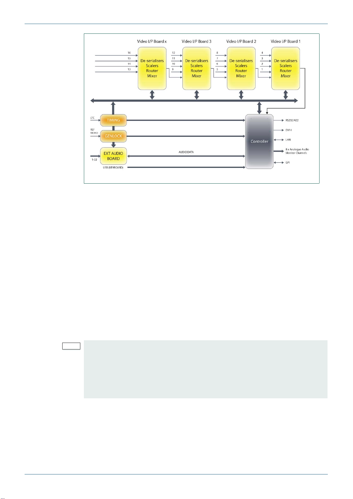
2.1 System concept
The modular architecture is designed for scalability. Of the two 3U frame types available, the
single multiviewer frame (MV-64), is equipped with one controller (CPU), one Buffer card and
one power supply module (PSU). The dual multiviewer frame (MV-32) is centrally divided and
capable of housing two separate multiviewers, each with its own CPU and Buffer card. The
Buffer card generates the 5 Volt power and distributes it to the rear cards. The card also
buffers signals generated on the CPU (such as clocks, data and I2C) and distributes them to
the VIP cards and rears.
Each video input card handles 4 sources. The single MV-64 frame will accommodate up to 16
video cards, providing a maximum capacity of 64 video channels. The dual MV-32 frame
provides a maximum capacity of 32 video channels for each multiviewer (8 video cards per
side). The video cards include support for SDI embedded audio. If external audio interfacing
is required, audio input or output cards may be fitted. These will reduce the capacity available
for video cards in the MV-32 but the MV-64 has two dedicated audio slots in addition to
16 video/audio slots. A maximum of eight audio cards (any mix of input and output) can be
fitted in an MV-64 multiviewer.
The video input cards will simultaneously support sources of differing rate, for example, 50Hz
and 60Hz. However, synchronisation is achieved by frame add and drop rather than
standards conversion. The system rate is either locked to the reference signal provided or a
designated video input source.
MV-32/64 Multiviewer www.snellgroup.com Introduction
Issue 1 Rev 11 Page 10 © 2014 Snell Limited
A scaler on each video card processes one of the possible input sources and scales it to the
desired tile size for the selected position on the display output. A mixer on each video card
combines all the video tiles and sends the resulting image to the next video card. The final
display output comprises all of the tiles in a single picture.
2.1.1 Video Input Card types
Possible video inputs are shown below. For details of card and Multiviewer firmware
compatibility see Table 1. on page 11.
•Card Type MV-VIP3 - Composite (limited to 2 inputs per card, inputs 1 and 2),
SD-SDI, HD-SDI 3 Gb/s (Level A) & 1.5 Gb/s (up to 4 inputs per card)
•Card Type MV-VIP3D - Composite (limited to 2 inputs per card, inputs 1 and 2),
SD-SDI, HD-SDI 3 Gb/s (Level A) & 1.5 Gb/s, including Dolby E level metering (up to
4 inputs per card)
•Card Type MV-VIP1 - (no longer supplied) - Composite, S-video, RGB, YUV, SD-SDI,
DVI-I
•Card Type MV-VIP2 - (no longer supplied) - Composite, S-video, RGB, YUV, SD-SDI,
HD-SDI 3 Gb/s (Level A) & 1.5 Gb/s, DVI-I
Overlay of audio and graphics information is performed inside each scaler, which receives
control data from the main CPU in real-time for external audio sources, or from the video card
itself in the case of embedded SDI/HD-SDI audio.
To allow arbitrary layering of sources, each input board has information about all of the tile
positions, allowing each tile to be displayed as required and enabling picture overlay with
complex borders.
Fig 1. The MV-32/MV-64 System Concept.
Note:
• The MV-VIP1 and MV-VIP2 cards were supplied with earlier multiviewers and are
shown in this manual for users that already have them fitted.
• The MV-VIP3 and MV-VIP3D cards cannot be mixed with MV-VIP1 or MV-VIP2
cards in the multiviewer frame because they use different versions of firmware.
If MV-VIP3 or 3D cards are to be fitted in a multiviewer frame that contains
MV-VIP1 or MV-VIP2 cards they must first be removed and replaced with MV-VIP3
or 3D cards.

MV-32/64 Multiviewer www.snellgroup.com Introduction
Issue 1 Rev 11 Page 11 © 2014 Snell Limited
2.1.2 Audio Input Card Types
Non-embedded external audio sources are supported by dedicated input cards.
• Card Type MV-AIA - analog, 32 channels (16 pairs)
• Card Type MV-AID - Digital, 16 AES/EBU pairs
2.1.3 Audio Output Card Types
Optional audio outputs are supported by dedicated output cards.
• Card Type MV-AOP1A: 32 channel analog audio output
• Card Type MV-AOP1D: 16 AES/EBU pairs audio output
2.1.4 Card Type/Firmware Version Compatibility
The MV-VIP3 and MV-VIP3D cards cannot be mixed with MV-VIP1 or MV-VIP2 cards in a
multiviewer frame because they use different versions of firmware. All cards fitted in a
Multiviewer frame run on the same firmware version and must be compatible with that
firmware version.
The following table gives details of the firmware that each of the card types is compatible with.
Note:
• For audio card rules and limitations see appendix D.1.1 and D.1.1.1.
Note:
• For audio card rules and limitations see appendix D.1.1 and D.1.1.1.
Important:
If MV-VIP3 or 3D cards are to be fitted in a multiviewer frame that contains MV-VIP1 or
MV-VIP2 cards they must first be removed and replaced with MV-VIP3 or 3D cards.
Card Type Multiviewer
Firmware
Version 2.X.X
Multiviewer
Firmware
Version 3.X.X
Video Input Cards:
MV-VIP3 No Yes
MV-VIP3D No Yes
MV-VIP1 (No longer supplied) Yes No
MV-VIP2 (No longer supplied) Yes No
Audio Input Cards:
MV-AIA Yes Yes
MV-AID Yes Yes
Audio Output Cards:
MV-AOP1A Yes Yes
MV-AOP1D Yes Yes
Table 1. Card Type and Firmware Version Compatibility Table

MV-32/64 Multiviewer www.snellgroup.com Introduction
Issue 1 Rev 11 Page 12 © 2014 Snell Limited
2.2 Features and benefits
• Single multiviewer with up to 64 auto-sensing video inputs, or dual multiviewer with up
to 2 x 32 video inputs in a 3U frame (multi-definition capable up to 3G 1080p)
• DVI-I output up to 1080p60 (1920x1080) in 16:9
• Genlocked inputs for flicker-free and full frame operation
•MV-VIP3/3D - Teletext subtitles display (WST on SD-SDI or OP-47 on HD-SDI).
•MV-VIP2 - Teletext subtitles display (WST on composite and SDI or OP-47 on
HD-SDI) and WSS.
•MV-VIP1 - Teletext subtitles display (WST on composite) and WSS.
• AFD decoding for adjusting the aspect ratio
• D-VITC and ancillary timecode decoding and display (SD-SDI/HD-SDI sources only)
• Audio metering is supported for up to 16 mono channels per display tile with MV-VIP2
cards or up to 32 mono channels per display tile with MV-VIP3 and MV-VIP3D cards.
•MV-VIP3D only - Audio metering of Dolby E encoded on any SDI embedded audio
pair. Up to four Dolby encoded pairs per SDI source can be metered. In total 32 mono
audio channels can be metered. Decoding of Dolby E audio content is not supported.
• Audio may be sourced from SD-SDI/HD-SDI 3Gb/s (Level A) & 1.5 Gb/s embedded
audio groups (PCM or *Dolby E), or externally via optional analog and AES/EBU (with
SRC) interfaces. *Dolby E - MV-VIP3D only.
• 4 pairs of assignable analog audio monitor outputs
• Up to 32 channels of audio per output card (analogue or AES/EBU), sourced from any
embedded audio input (PCM only, not Dolby E decoded), or from external audio input
cards.
• Alarms for video, audio and metadata, with outputs to, GPI Outputs, LAN and/or
SNMP traps
• Assignable tallies
• Under Monitor Displays (UMD) entered via keyboard, LAN or serial cable, supporting
TSL and other protocols
• Clock display receiving time information via NTP network protocol or LTC
• 3 RU compact design, ideal for OB-vans and other space restricted installations
• Optional external backup power supply
• User-friendly set-up via browser software

MV-32/64 Multiviewer www.snellgroup.com Introduction
Issue 1 Rev 11 Page 13 © 2014 Snell Limited
2.2.1 Powerful alarms
Alarms may be created for video sync loss, black (loss of luminance), freeze-frame,
embedded audio loss, external audio loss, over level, out of phase (of chosen pairs), teletext
loss, and closed caption loss. Audio alarms can be configured to be displayed above the
audio bars and/or in text boxes.
The colors used for on-screen alarms located above the audio bars are as follows:
• Audio Loss: Yellow - position (left or right) indicates channel
• Audio Over: Red - position (left or right) indicates channel
• Anti-Phase: Cyan - middle alarm
• Carrier Loss: White - middle alarm
If carrier loss occurs, only that alarm will flash, unless audio loss had already been active for
the same channel.
Alarms are also available for WST, OP-47 and closed caption loss.
On screen alarm indication may be a stationary or flashing colored tile border. External alarm
indication may be via the GPI I/O or the LAN/software application.
Optional triggering of SNMP traps for each alarm function or group is also supported.
Tiles have an optional color coded border to provide status indication, such as tally or alarms.
VITC loss is indicated by the burnt in VITC display flashing. Burnt in VITC is available from
SDI sources only.
2.2.2 Captions and UMDs
Captions or Under Monitor Display (UMD) information may be generated manually from a
keyboard connected to a front panel USB-2 port or automatically from remote sources via the
LAN, using browser software operating on a remote PC, or via the RS232/422 port using TSL
or other protocols. Up to two lines of UMD text can be left, centre, or right justified and may be
placed anywhere in the tile.
2.2.3 Using bitmaps
There is storage capacity (approximately 200MB) for bitmaps. These can be used as
backgrounds, or to display station idents, etc. The bitmaps must be in bmp or png file format
and can be uploaded to the frame via the LAN. Up to four bitmaps may be displayed at any
one time.
2.2.4 Keeping time
Clock/date display data can be derived from several sources; the system clock, NTP
synchronisation, LTC, or VITC from a chosen SDI input.
If there is no LTC present, the frame searches the network for an NTP Server in the nearby
region (pool.ntp.org). If a server is found, the time is taken from that.
In the absence of any clock, the system time is used. A battery on the CPU board insures that
time data is retained if the unit be powered down.
Note:
When LTC is present this source becomes the exclusive reference for clocks.
The input is balanced; to use an unbalanced LTC input, the signal must be properly
converted with a Balun in-line transformer. Grounding either of the LTC input pins will not
work.
MV-32/64 Multiviewer www.snellgroup.com Introduction
Issue 1 Rev 11 Page 14 © 2014 Snell Limited
For each input is possible to display either the Ancillary Timecode or the DVITC from the
video source.
LTC is applied to the frame through a BNC on at the rear of the frame.
See section 4.5 for more information.
If VBI data is present on a video input and the video is an SDI source then the data can be
displayed on the relevant video tile (see sections 4.16.5.6 and 4.16.5.7 for setting details).
If multiple sources of timecode are present in a video source then the timecode selected for
display, in order of priority is; Ancillary VITC, Ancillary LTC and D-VITC.
2.2.5 Genlocking
Genlocking of the MV-32/MV-64 multiviewer is via SD color black or HD tri-level sync, using
the genlock input.
2.2.6 Using GPI I/O
Assignable GPI I/O with 16 inputs and 8 outputs for external alarm indication and tally
functions.
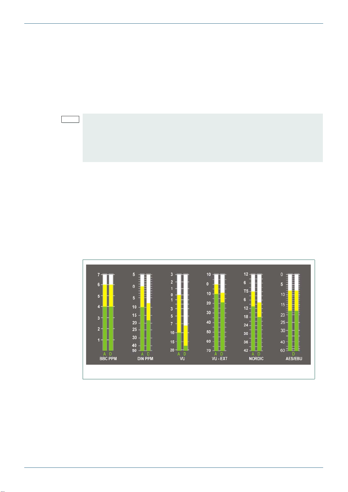
2.2.7 Bargraph scales
The following audio scales are supported:
Colors used for the upper and lower ranges of each bar type can be customized to satisfy any
in-house monitoring style for each of the six scale types.
For the MV-VIP3D cards the meters can be configured appropriately to display the levels of all
channels in a Dolby E stream (embedded audio only, not audio from external audio input
cards).
Note:
1. D-VITC is only available on SD sources as there is currently no standard for HD
sources. Ancillary Timecode is available on both SD and HD sources.
2. The Timecode is displayed in a fixed position near the bottom center of the tile
within the video.
3. The display will start to be cropped when the tile is 150 pixels or less wide.
Fig 2. Available Meter Scales.
MV-32/64 Multiviewer www.snellgroup.com Installation
Issue 1 Rev 11 Page 15 © 2014 Snell Limited
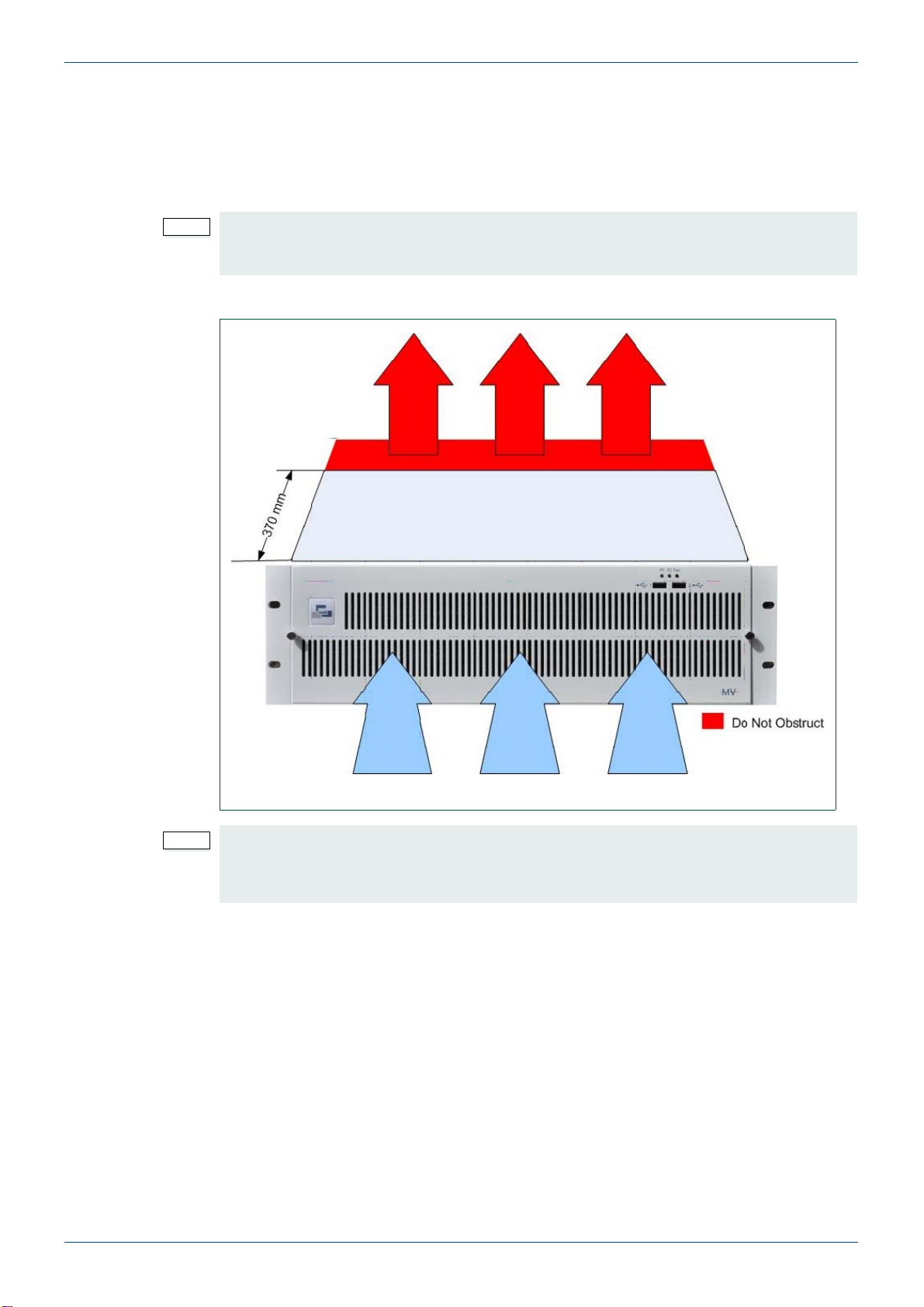
3. Installation
The MV-32/MV-64 multiviewer 3U frame may be installed in 19 inch bays and has a depth of
approximately 462mm, including connectors. Ventilation is assisted by cooling fans located
on the removable front panel of the frame. Exhaust grilles are located on the upper, lower and
side panels, at a depth of approximately 370 mm from the front panel.
Maximum operating ambient temperature must not exceed 40oC.
Note:
If installing other equipment immediately above or below, it is essential that the ventilation
outlets are not obstructed. Frames should be installed into bays such that airflow is not
impeded in any way.
Fig 3. The 3U MV-32/MV-64 Multiviewer Frame Showing Ventilation Airflow.
Note:
The front rack ears are intended to provide a means of retaining the unit in the rack.
To ensure adequate support the unit MUST also be supported at the rear of the frame.
Please ensure that ventilation is not impaired when selecting suitable supports.

MV-32/64 Multiviewer www.snellgroup.com Installation
Issue 1 Rev 11 Page 16 © 2014 Snell Limited
3.1 Power and fuses
The mains voltage (240/100 volts) will be auto detected provided it is in the range
90 - 264 V AC 50/60Hz. A 5A fuse is fitted and a spare fuse should be located under the
pull-out flap.
The IEC power inlet is the mains disconnection device for this unit.
3.2 Health and safety considerations
The Installation and Maintenance of the MV-32/MV-64 multiviewer unit and any associated
equipment must be carried out by PERSONS SUITABLY QUALIFIED to work with equipment
which may be connected to the mains supply.
The unit MUST BE DISCONNECTED & ISOLATED FROM THE MAINS INPUT and from
other product outputs before undertaking maintenance.
ELECTRIC SHOCK HAZARDS exist if conductive instruments, neck chains or fingers etc. are
placed within the unit or in close proximity of the input/output terminals/connectors.
Incorrect installation can cause internal components to rupture and particles to be ejected
from the product.
TOXIC FUME HAZARDS exist if the unit is subjected to direct flames or excessive
temperature of above 100 Degrees Centigrade ambient.
The mounting and installation of the unit must be arranged by the user to comply with all
safety regulations by the indigenous authority.
3.2.1 Disposal
Do not incinerate as explosive and toxic fume hazards exist. Disposal must be by dismantling
the product to component level and disposing of each component by an approved method.
3.2.2 FCC Compliance
In order to comply with FCC/CFR47: Part 15 regulations, it is necessary to use the following
specification of cable assemblies for DVI interconnections:
• For DVI to DVI interconnection, use a high-quality triple-screened cable assembly for
optimum RF/EMI integrity in compliance with DVI specifications.
• For DVI to HDMI interconnection, use a high-quality triple-screened cable assembly,
with integrated ferrite suppression at both ends of the cable for optimum RF/EMI
integrity in compliance with DVI and HDMI specifications.
This equipment has more than one power supply cord. To reduce the risk of electrical
shock, disconnect all the power supply cords before servicing.
For your own protection, observe the following safety precautions when installing,
operating and servicing your device:

MV-32/64 Multiviewer www.snellgroup.com Installation
Issue 1 Rev 11 Page 17 © 2014 Snell Limited
3.3 Connector I/O
The multiviewers use coaxial BNCs for the video inputs, LTC and sync inputs. Microcross
connectors are used for DVI-I inputs and outputs. External audio connections (input or output)
are via female 44 way D-Type connectors, with audio monitoring outputs on a male 25 way
D-Type connector.
The global GPI I/O connector is a high density 26 way female D-Type connector. Local video
card GPI I/O connections are via 15 way female D-Type connectors. There are two USB
connectors on the front panel for keyboard connection and auxiliary functions.
The serial ports comprise a pair of 9 way female D-Type connectors and a pair of standard
RJ45 connectors are provided for LAN connection. The LAN-1 & RS422-1 ports serve the
CPU/Buffer cards fitted in the left of the frame as viewed from the rear panel (the right when
viewed from the front of the multiviewer). The LAN-2 & RS422-2 ports serve the CPU/Buffer
cards fitted in the centre of the multiviewer (MV-32 dual frames only).
3.3.1 Example: MV-32 Dual Multiviewer Rear Panel Connections
The MV-32 dual multiviewer shown below is fully equipped with single width video rear
panels.
Note:
MV-VIP3 and MV-VIP3D cards cannot be used with DVI inputs or Component video inputs.
Fig 4. Example MV-32 Dual Multiviewer 3U Dual Frame Rear Connector I/O.
Note:
• If Audio cards are fitted they must be fitted in the slots immediately following the
last populated video card slot, see Appendix D.1.1 for further details.
• Slots 1 and 2 are not compatible with audio cards. If audio cards are installed a
minimum of one video card must be fitted in slot 1 with a loop through rear panel.
This allows the first audio card to be fitted in slot 3.
• When fitted with a second CPU/buffer card slots 13 and 14 are not compatible with
audio cards. If audio cards are installed a minimum of one video card must be fitted
in slot 13 with a loop through rear panel. This allows the first audio card to be fitted
in slot 15.
• Composite video input signals can only be connected to the bottom two BNC
connectors of the rear panel when MV-VIP3 & MV-VIP3D cards are fitted.
Video
Input 4
Video
Input 32
Video
Input 1
Video
Input 29
Video
Input 4
Video
Input 32
Video
Input 1
Video
Input 29
CPU/Buffer Cards
(LAN-1 & RS422-1)
CPU/Buffer Cards
(LAN-2 & RS422-2)
LAN-1, RS422-1
LAN-2, RS422-2

MV-32/64 Multiviewer www.snellgroup.com Installation
Issue 1 Rev 11 Page 18 © 2014 Snell Limited
3.3.2 Example: MV-64 Multiviewer Rear Panel Connections
The MV-64 multiviewer shown below is fully equipped with single width video rear panels and
two audio cards.
3.4 Input card configurations
The MV-32/MV-64 multiviewer may be fitted with up to sixteen MV-VIP3*, MV-VIP3D*
MV-VIP1* or MV-VIP2* video input cards. See section 2.1.4 for details on card and frame
firmware compatibility.
Frame configuration options also include video loop-through and external audio I/O cards,
which will reduce the total capacity available for video input cards.
MV-VIP3 and MV-VIP3D video cards support the following standards:
• Composite video PAL/NTSC, CVBS - 1Vpp (limited to 2)
• SDI - SMPTE 259M
• HD-SDI up to SMPTE 292M 3G
Fig 5. Example MV-64 Multiviewer 3U Frame Rear Connector I/O.
Note:
• Slots 1 and 2 are not compatible with audio cards. If audio cards are installed a
minimum of one video card must be fitted in slot 1 with a loop through rear panel.
This allows the first audio card to be fitted in slot 3.
• Slots 17 and 18 are reserved for Audio cards but can’t be used until slots 1 to 16
have been filled, see Appendix D.1.1.1 for further details.
• A maximum of 8 audio cards (any mix of input and output) can be fitted in an MV-64
multiviewer.
• Composite video input signals can only be connected to the bottom two BNC
connectors of the rear panel for MV-VIP3 & MV-VIP3D cards.
Video
Input 4
Video
Input 1
Video
Input 64
Video
Input 61
CPU/Buffer Cards
(LAN 1 & RS422-1)
Slots 17 & 18 reserved for
Audio Cards (optional)
LAN 1, RS422-1
LAN 2, RS422-2
(Not Used)
Note:
*The MV-VIP3 and MV-VIP3D cards cannot be mixed with MV-VIP1 or MV-VIP2 cards in
the multiviewer frame because they use different versions of firmware.
If MV-VIP3 or 3D cards are to be fitted in a multiviewer frame that contains MV-VIP1 or
MV-VIP2 cards they must first be removed and replaced with MV-VIP3 or 3D cards.
See section 2.1.4 for details on card and frame firmware compatibility.

MV-32/64 Multiviewer www.snellgroup.com Installation
Issue 1 Rev 11 Page 19 © 2014 Snell Limited
MV-VIP2 video cards support the following standards (no longer supplied):
• Composite video PAL/NTSC, CVBS - 1Vpp
• SDI - SMPTE 259M
• HD-SDI up to SMPTE 292M 3G
• DVI-I - digital or analog component, 1920 x 1080
• S-Video (Y/C)
• Component video RGB/YUV
MV-VIP1 video cards support the following standards (no longer supplied):
• Composite video PAL/NTSC, CVBS - 1Vpp
• SDI - SMPTE 259M
• DVI-I - digital or analog component, 1920 x 1080
• S-Video (Y/C)
• Component video RGB/YUV
Fig 6. Example MV-32 Multiviewer 3U Dual Frame With Front Door Open.
Fig 7. Example MV-64 Multiviewer 3U Single Frame With Front Door Open.
PSUCPU CardBuffer CardCPU CardBuffer Card
LAN-1 & RS422-1
LAN-2 & RS422-2
CPU Card PSUBuffer Card
LAN-1 & RS422-1

MV-32/64 Multiviewer www.snellgroup.com Installation
Issue 1 Rev 11 Page 20 © 2014 Snell Limited
The CPU card, Buffer card and PSU module are located in fixed positions within both the
single (MV-64) and dual (MV-32) multiviewer frames. A CPU card will always be fitted to slot 1
and a buffer card in slot 2. A dual frame MV-32 multiviewer will additionally have a CPU card
fitted in slot 11 and a buffer card in slot 12.
Video and audio cards are installed in the remaining slots in sequence, from right to left, as
viewed from the front.
3.4.1 Video Inputs
Separate rear connector modules of the required type are fitted to allow interfacing with each
input card. These are available with different combinations of BNC and Microcross DVI-I
connectors to suit the application. A single BNC connector is used for formats such as
SD-SDI, HD-SDI and *Composite video. For S-Video, two BNC connectors are required, for
RGB/YUV three BNC connectors are required.
Most video input card connector modules are also equipped with an 8 x GPI port, although in
some instances, insufficient space is available.
3.4.2 Video Outputs
The two DVI-I display outputs (per multiviewer) support resolutions up to HD 1080p60, 16:9
(1920 x 1080). Both digital and analog outputs are available on these connectors. Tiles
displayed via the outputs can be varied continuously in size and position, cropped or
displayed in pre-configured screen layouts on a chosen colored background. The pair of
outputs may either be set to provide two identical display configurations, or they may have
differing arrangements.
3.4.3 Audio I/O
Audio levels may be displayed using up to 16 bargraphs in each tile (32 bargraphs per tile
with MV-VIP3D cards), either superimposed on each video image or outside active video.
Audio is derived from the incoming embedded audio (when using SD-SDI or HD-SDI inputs),
or from external sources, for which the appropriate audio input card option must be installed.
Optional audio output cards (32 channels analog or 16 AES/EBU pairs) may be fitted to
provide demuxed outputs from embedded audio.
Audio input and output cards must be fitted in conjunction with the appropriate rear connector
modules.
There is an 8 channel analog audio monitor output, which may be assigned from any input
channel of any format, excluding incoming external audio level data.
All bargraph scales and ballistics conform to international standards and include BBC PPM,
DIN PPM, Nordic PPM, VU, extended VU, and AES/EBU digital.
Note:
The I/O cards are not hot-swappable and the multiviewer must be powered down when
inserting and removing cards.
Note:
• Component and DVI inputs are not supported by the MV-VIP3 and MV-VIP3D
cards.
• *Only inputs 1 and 2 can be used for Composite video on MV-VIP3 and MV-VIP3D
cards.
Note:
The number of audio channels described always refers to individual channels, not channel
pairs. For example, eight monitor outputs relate to eight individual analog channels or 4
pairs AES/EBU channels.
This manual suits for next models
1
Table of contents
Other Snell Switch manuals


Popular Switch manuals by other brands


Tippkemper-Matrix
Tippkemper-Matrix IRS-OFN Series operating manual

Xantech
Xantech D5XH installation instructions

Jedia
Jedia JFS-381 operating instructions

Kinivo
Kinivo 350BN user manual

Rose electronics
Rose electronics MultiVideo HDMI MDM-4T2HD-A1MultiVideo HDMI... Installation and operation manual

Rompa
Rompa GUMDROP 17772 quick start guide

Allied Telesis
Allied Telesis AT-RH505BE Quick install guide

ATEN
ATEN Altusen KH1508a quick start guide

Linkskey
Linkskey LKV-248AUSK Quick installation guide

StarTech.com
StarTech.com HB30A3A1CST quick start guide

NETGEAR
NETGEAR M4100 Series ProSAFE installation guide

Lencore
Lencore G420 Installation & operation manual