Snell VEGA-16MV User manual

www.s-a-m.com
User Manual
Vega-MV Router Multiviewer
Video Routing and Multiviewer Outputs

Vega-MV Router Multiviewer - User Manual
Issue 1 Revision 2 Page 2 © 2017 SAM
Contents
Contents
1 Information and Notices . . . . . . . . . . . . . . . . . . . . . . . . . . . . . . . . . . . . . . . . . . . . . . . 7
1.1 Customer Support . . . . . . . . . . . . . . . . . . . . . . . . . . . . . . . . . . . . . . . . . . . . . . . . . 7
1.2 Copyright and Disclaimer . . . . . . . . . . . . . . . . . . . . . . . . . . . . . . . . . . . . . . . . . . . 7
1.3 Trademarks . . . . . . . . . . . . . . . . . . . . . . . . . . . . . . . . . . . . . . . . . . . . . . . . . . . . . . 7
2 Safety . . . . . . . . . . . . . . . . . . . . . . . . . . . . . . . . . . . . . . . . . . . . . . . . . . . . . . . . . . . . . . 8
2.1 Explanation of Safety Symbols . . . . . . . . . . . . . . . . . . . . . . . . . . . . . . . . . . . . . . . 8
2.2 Mains Power Supply . . . . . . . . . . . . . . . . . . . . . . . . . . . . . . . . . . . . . . . . . . . . . . 10
2.3 Health and Safety Considerations. . . . . . . . . . . . . . . . . . . . . . . . . . . . . . . . . . . . 10
2.4 Lithium Batteries . . . . . . . . . . . . . . . . . . . . . . . . . . . . . . . . . . . . . . . . . . . . . . . . . .11
2.5 Rack Mounting . . . . . . . . . . . . . . . . . . . . . . . . . . . . . . . . . . . . . . . . . . . . . . . . . . .11
2.6 Compliance Standards . . . . . . . . . . . . . . . . . . . . . . . . . . . . . . . . . . . . . . . . . . . . .11
2.7 EMC Standards: . . . . . . . . . . . . . . . . . . . . . . . . . . . . . . . . . . . . . . . . . . . . . . . . . .11
3 Product Introduction. . . . . . . . . . . . . . . . . . . . . . . . . . . . . . . . . . . . . . . . . . . . . . . . . 13
3.1 Application Areas . . . . . . . . . . . . . . . . . . . . . . . . . . . . . . . . . . . . . . . . . . . . . . . . 13
3.2 Features . . . . . . . . . . . . . . . . . . . . . . . . . . . . . . . . . . . . . . . . . . . . . . . . . . . . . . . 14
3.3 Order Codes . . . . . . . . . . . . . . . . . . . . . . . . . . . . . . . . . . . . . . . . . . . . . . . . . . . . 15
3.4 Vega-MV Inputs and Outputs . . . . . . . . . . . . . . . . . . . . . . . . . . . . . . . . . . . . . . . 16
3.5 Functional Description. . . . . . . . . . . . . . . . . . . . . . . . . . . . . . . . . . . . . . . . . . . . . 18
3.5.1 Vega-MV Components . . . . . . . . . . . . . . . . . . . . . . . . . . . . . . . . . . . . . . . . 20
3.5.2 Using GPI I/O . . . . . . . . . . . . . . . . . . . . . . . . . . . . . . . . . . . . . . . . . . . . . . . 22
3.5.3 Genlocking and Reference . . . . . . . . . . . . . . . . . . . . . . . . . . . . . . . . . . . . . 22
3.6 On-screen Notifications . . . . . . . . . . . . . . . . . . . . . . . . . . . . . . . . . . . . . . . . . . . . 22
3.6.1 Powerful Alarms . . . . . . . . . . . . . . . . . . . . . . . . . . . . . . . . . . . . . . . . . . . . . 22
3.6.2 Captions and UMDs . . . . . . . . . . . . . . . . . . . . . . . . . . . . . . . . . . . . . . . . . . 23
3.6.3 Using Still Images . . . . . . . . . . . . . . . . . . . . . . . . . . . . . . . . . . . . . . . . . . . . 23
3.6.4 Keeping Time . . . . . . . . . . . . . . . . . . . . . . . . . . . . . . . . . . . . . . . . . . . . . . . 23
3.6.5 Bargraph Scales . . . . . . . . . . . . . . . . . . . . . . . . . . . . . . . . . . . . . . . . . . . . . 23
3.7 Vega-MV Monitoring and Switching Signals . . . . . . . . . . . . . . . . . . . . . . . . . . . . 24
3.8 Thermal Protection, Thermal Shutdown . . . . . . . . . . . . . . . . . . . . . . . . . . . . . . . 25
3.8.1 MV-NET Card Thermal Protection. . . . . . . . . . . . . . . . . . . . . . . . . . . . . . . . 25
3.8.2 MV-1000PSU - Power Supply Module Thermal Protection. . . . . . . . . . . . . 26
3.9 External Power Supply Shelf, MV-EXTPSU3 . . . . . . . . . . . . . . . . . . . . . . . . . . . 26
4 Vega-MV Unit Hardware . . . . . . . . . . . . . . . . . . . . . . . . . . . . . . . . . . . . . . . . . . . . . . 27
4.1 Vega-MV Unit’s Components . . . . . . . . . . . . . . . . . . . . . . . . . . . . . . . . . . . . . . . 27
4.2 Unit Front Panel . . . . . . . . . . . . . . . . . . . . . . . . . . . . . . . . . . . . . . . . . . . . . . . . . 28
4.2.1 Front Panel Status LEDs. . . . . . . . . . . . . . . . . . . . . . . . . . . . . . . . . . . . . . . 28
4.2.2 Front Panel OLED Display . . . . . . . . . . . . . . . . . . . . . . . . . . . . . . . . . . . . . 29
4.2.3 Unit Serial Number Label . . . . . . . . . . . . . . . . . . . . . . . . . . . . . . . . . . . . . . 30
4.3 Unit Rear . . . . . . . . . . . . . . . . . . . . . . . . . . . . . . . . . . . . . . . . . . . . . . . . . . . . . . . 31
4.3.1 LAN 0 Default IP Addresses . . . . . . . . . . . . . . . . . . . . . . . . . . . . . . . . . . . . 33
4.3.2 LAN 1 Default IP Addresses . . . . . . . . . . . . . . . . . . . . . . . . . . . . . . . . . . . . 33
4.4 Card Slots . . . . . . . . . . . . . . . . . . . . . . . . . . . . . . . . . . . . . . . . . . . . . . . . . . . . . . 34
4.4.1 Card Slot Numbering. . . . . . . . . . . . . . . . . . . . . . . . . . . . . . . . . . . . . . . . . . 34
4.4.2 Component Card Slot Locations . . . . . . . . . . . . . . . . . . . . . . . . . . . . . . . . . 34
4.5 MV-NET Card and Rear Module - Slot 0 . . . . . . . . . . . . . . . . . . . . . . . . . . . . . . . 37
4.5.1 MV-NET Front Module - Front Slot 0 only. . . . . . . . . . . . . . . . . . . . . . . . . . 37
4.5.2 MV-NET Rear Panel Module (Part MV-NRP1) - Rear Slot 0 only . . . . . . . . 38
4.5.3 GPI Input/Output Connectors . . . . . . . . . . . . . . . . . . . . . . . . . . . . . . . . . . . 38
4.5.4 Serial Comms Port Mode of Operation . . . . . . . . . . . . . . . . . . . . . . . . . . . . 40
4.5.5 Serial Comms Port Pin Assignments . . . . . . . . . . . . . . . . . . . . . . . . . . . . . 41
4.6 MV-CTL Card and Rear Module - Slot 1 . . . . . . . . . . . . . . . . . . . . . . . . . . . . . . . 42
4.6.1 MV-CTL Front Module - Slot 1. . . . . . . . . . . . . . . . . . . . . . . . . . . . . . . . . . . 42
4.6.2 MV-CTL Rear Panel Module (Part MV-RMVCS8) - Rear Slot 1 . . . . . . . . . 42
4.7 MV-VIP4 Card and Rear Module - Slots 2 to 5 . . . . . . . . . . . . . . . . . . . . . . . . . . 45
4.7.1 MV-VIP4 Front Modules - Slots 2 to 5 . . . . . . . . . . . . . . . . . . . . . . . . . . . . . 46

Vega-MV Router Multiviewer - User Manual
Issue 1 Revision 2 Page 3 © 2017 SAM
Contents
4.7.2 MV-VIP4 Rear Panel Modules (Part MV-RMVRO8) - Slots 2 to 5. . . . . . . . 46
4.8 Dust Blanking Rear Panel (MV-BRP) . . . . . . . . . . . . . . . . . . . . . . . . . . . . . . . . . 47
4.9 Vega-MV Power Supply Connectors . . . . . . . . . . . . . . . . . . . . . . . . . . . . . . . . . . 48
4.9.1 Mains AC Supply Inlet. . . . . . . . . . . . . . . . . . . . . . . . . . . . . . . . . . . . . . . . . 48
4.9.2 24V DC Backup Power Inlet . . . . . . . . . . . . . . . . . . . . . . . . . . . . . . . . . . . . 48
5 Vega-MV Installation . . . . . . . . . . . . . . . . . . . . . . . . . . . . . . . . . . . . . . . . . . . . . . . . . 49
5.1 Ventilation . . . . . . . . . . . . . . . . . . . . . . . . . . . . . . . . . . . . . . . . . . . . . . . . . . . . . . 50
5.1.1 Vega-MV . . . . . . . . . . . . . . . . . . . . . . . . . . . . . . . . . . . . . . . . . . . . . . . . . . . 50
5.1.2 MV-EXTPSU3 Backup Power Supply . . . . . . . . . . . . . . . . . . . . . . . . . . . . . 51
5.2 Rack Mounting . . . . . . . . . . . . . . . . . . . . . . . . . . . . . . . . . . . . . . . . . . . . . . . . . . 51
5.2.1 Before Rack Mounting. . . . . . . . . . . . . . . . . . . . . . . . . . . . . . . . . . . . . . . . . 51
5.2.2 Mounting in a Rack . . . . . . . . . . . . . . . . . . . . . . . . . . . . . . . . . . . . . . . . . . . 51
5.2.3 Before Powering . . . . . . . . . . . . . . . . . . . . . . . . . . . . . . . . . . . . . . . . . . . . . 52
5.3 FCC Compliance . . . . . . . . . . . . . . . . . . . . . . . . . . . . . . . . . . . . . . . . . . . . . . . . . 52
5.4 HDMI Cable Retention Options. . . . . . . . . . . . . . . . . . . . . . . . . . . . . . . . . . . . . . 53
5.4.1 HDMI with Integral Screw Fitting. . . . . . . . . . . . . . . . . . . . . . . . . . . . . . . . . 53
5.4.2 HDMI Connector without a Fixing System. . . . . . . . . . . . . . . . . . . . . . . . . . 54
5.4.3 HDMI Connector with Friction Lock. . . . . . . . . . . . . . . . . . . . . . . . . . . . . . . 54
5.5 Vega-MV Power Supplies and Fuses . . . . . . . . . . . . . . . . . . . . . . . . . . . . . . . . . 55
5.6 Vega-MV Frame Power Supplies . . . . . . . . . . . . . . . . . . . . . . . . . . . . . . . . . . . . 55
5.6.1 Mains AC Supply Power Socket . . . . . . . . . . . . . . . . . . . . . . . . . . . . . . . . . 55
5.6.2 DC Backup Power Input Connector . . . . . . . . . . . . . . . . . . . . . . . . . . . . . . 56
5.7 Powering Up (Unit Start Up) . . . . . . . . . . . . . . . . . . . . . . . . . . . . . . . . . . . . . . . . 57
6 Front Panel Operation. . . . . . . . . . . . . . . . . . . . . . . . . . . . . . . . . . . . . . . . . . . . . . . . 59
6.1 Front Panel . . . . . . . . . . . . . . . . . . . . . . . . . . . . . . . . . . . . . . . . . . . . . . . . . . . . . 59
6.1.1 General Status Display . . . . . . . . . . . . . . . . . . . . . . . . . . . . . . . . . . . . . . . . 59
6.2 Front Panel Operational Settings Screens . . . . . . . . . . . . . . . . . . . . . . . . . . . . . 61
6.2.1 Accessing Other Unit Operating Settings . . . . . . . . . . . . . . . . . . . . . . . . . . 61
6.2.2 Editing Settings . . . . . . . . . . . . . . . . . . . . . . . . . . . . . . . . . . . . . . . . . . . . . . 64
7 Web Interface. . . . . . . . . . . . . . . . . . . . . . . . . . . . . . . . . . . . . . . . . . . . . . . . . . . . . . . 67
7.1 The Web Interface. . . . . . . . . . . . . . . . . . . . . . . . . . . . . . . . . . . . . . . . . . . . . . . . 68
7.1.1 Menu Bar. . . . . . . . . . . . . . . . . . . . . . . . . . . . . . . . . . . . . . . . . . . . . . . . . . . 70
7.1.2 Main Tool Bar . . . . . . . . . . . . . . . . . . . . . . . . . . . . . . . . . . . . . . . . . . . . . . . 70
7.1.3 Lost Connection . . . . . . . . . . . . . . . . . . . . . . . . . . . . . . . . . . . . . . . . . . . . . 71
7.2 Workspace and the Web Interface . . . . . . . . . . . . . . . . . . . . . . . . . . . . . . . . . . . 72
7.2.1 Tile Object: . . . . . . . . . . . . . . . . . . . . . . . . . . . . . . . . . . . . . . . . . . . . . . . . . 74
7.2.2 Video Object Tiles . . . . . . . . . . . . . . . . . . . . . . . . . . . . . . . . . . . . . . . . . . . . 74
7.2.3 Object and Source Explorer . . . . . . . . . . . . . . . . . . . . . . . . . . . . . . . . . . . . 76
7.2.4 Edit Object Menu. . . . . . . . . . . . . . . . . . . . . . . . . . . . . . . . . . . . . . . . . . . . . 77
7.3 Module Menu. . . . . . . . . . . . . . . . . . . . . . . . . . . . . . . . . . . . . . . . . . . . . . . . . . . . 78
7.3.1 Setup Module - Module Properties Dialog. . . . . . . . . . . . . . . . . . . . . . . . . . 80
7.3.2 Setup Selected Video Source - Source Properties Dialog . . . . . . . . . . . . 102
7.3.3 Ext. Audio Source Properties (Not applicable to Vega-MV) . . . . . . . . . . . 109
7.3.4 Setup Audio Meter Properties . . . . . . . . . . . . . . . . . . . . . . . . . . . . . . . . . . .110
7.3.5 SDI I/O Router Dialog (for the Internal Router) . . . . . . . . . . . . . . . . . . . . . .111
7.3.6 Set Time . . . . . . . . . . . . . . . . . . . . . . . . . . . . . . . . . . . . . . . . . . . . . . . . . . .114
7.4 Layout Menu . . . . . . . . . . . . . . . . . . . . . . . . . . . . . . . . . . . . . . . . . . . . . . . . . . . .116
7.4.1 Setup Layout . . . . . . . . . . . . . . . . . . . . . . . . . . . . . . . . . . . . . . . . . . . . . . . .117
7.5 Group Menu . . . . . . . . . . . . . . . . . . . . . . . . . . . . . . . . . . . . . . . . . . . . . . . . . . . .118
7.6 Object Menu . . . . . . . . . . . . . . . . . . . . . . . . . . . . . . . . . . . . . . . . . . . . . . . . . . . .119
7.6.1 Edit Object Window. . . . . . . . . . . . . . . . . . . . . . . . . . . . . . . . . . . . . . . . . . 120
7.6.2 Edit Object - Type . . . . . . . . . . . . . . . . . . . . . . . . . . . . . . . . . . . . . . . . . . . 121
7.6.3 Edit Object - Border. . . . . . . . . . . . . . . . . . . . . . . . . . . . . . . . . . . . . . . . . . 122
7.6.4 Edit Object - Parent. . . . . . . . . . . . . . . . . . . . . . . . . . . . . . . . . . . . . . . . . . 122
7.6.5 Edit Object - Properties . . . . . . . . . . . . . . . . . . . . . . . . . . . . . . . . . . . . . . . 123
7.6.6 Edit Object - Properties, Source (Video or Audio object) . . . . . . . . . . . . . 124
7.6.7 Edit Object - Properties, Audio (Video or Audio object) . . . . . . . . . . . . . . 126

Vega-MV Router Multiviewer - User Manual
Issue 1 Revision 2 Page 4 © 2017 SAM
Contents
7.6.8 Edit Object - Properties, Error (Video or Audio object) . . . . . . . . . . . . . . . 132
7.6.9 Edit Object - Properties, Tally (Video object). . . . . . . . . . . . . . . . . . . . . . . 133
7.6.10 Edit Object - Properties, VBI (Video object) . . . . . . . . . . . . . . . . . . . . . . 134
7.6.11 Edit Object - Properties, WSS (Video object) . . . . . . . . . . . . . . . . . . . . . 136
7.6.12 Edit Object - Properties, SAG - Safe Area - (Video Object) . . . . . . . . . . 137
7.6.13 Edit Object - Properties, Text (Text object) . . . . . . . . . . . . . . . . . . . . . . . 138
7.6.14 Edit Object - Properties, Logo Tab (Logo object) . . . . . . . . . . . . . . . . . . 139
7.6.15 Edit Object - Properties, Clock (Clock object) . . . . . . . . . . . . . . . . . . . . . 140
7.6.16 Edit Object - Properties, Timer (Timer Object) . . . . . . . . . . . . . . . . . . . . 141
7.6.17 Edit Object - UMD Tab. . . . . . . . . . . . . . . . . . . . . . . . . . . . . . . . . . . . . . . 146
7.7 Grid Menu . . . . . . . . . . . . . . . . . . . . . . . . . . . . . . . . . . . . . . . . . . . . . . . . . . . . . 147
7.8 Help Menu. . . . . . . . . . . . . . . . . . . . . . . . . . . . . . . . . . . . . . . . . . . . . . . . . . . . . 148
7.8.1 Help > About . . . . . . . . . . . . . . . . . . . . . . . . . . . . . . . . . . . . . . . . . . . . . . . 148
7.8.2 Help > Logging . . . . . . . . . . . . . . . . . . . . . . . . . . . . . . . . . . . . . . . . . . . . . 149
8 Getting Started. . . . . . . . . . . . . . . . . . . . . . . . . . . . . . . . . . . . . . . . . . . . . . . . . . . . . 150
8.1 Unpacking . . . . . . . . . . . . . . . . . . . . . . . . . . . . . . . . . . . . . . . . . . . . . . . . . . . . . 150
8.2 Checking Internal Cards . . . . . . . . . . . . . . . . . . . . . . . . . . . . . . . . . . . . . . . . . . 151
8.3 Initial Network Setup . . . . . . . . . . . . . . . . . . . . . . . . . . . . . . . . . . . . . . . . . . . . . 152
8.3.1 Network Settings . . . . . . . . . . . . . . . . . . . . . . . . . . . . . . . . . . . . . . . . . . . . 152
8.4 Initial Unit Connections . . . . . . . . . . . . . . . . . . . . . . . . . . . . . . . . . . . . . . . . . . . 153
8.5 Set up Reference Input Format and Router Outputs. . . . . . . . . . . . . . . . . . . . . 154
8.6 Set Up Internal Router. . . . . . . . . . . . . . . . . . . . . . . . . . . . . . . . . . . . . . . . . . . . 154
8.7 Set Up Multiviewer Output Format . . . . . . . . . . . . . . . . . . . . . . . . . . . . . . . . . . 154
8.8 Set Up Multiviewer Layout. . . . . . . . . . . . . . . . . . . . . . . . . . . . . . . . . . . . . . . . . 154
8.9 Initial Basic Checks . . . . . . . . . . . . . . . . . . . . . . . . . . . . . . . . . . . . . . . . . . . . . . 155
9 Connection to Other Equipment . . . . . . . . . . . . . . . . . . . . . . . . . . . . . . . . . . . . . . 156
9.1 RS232/RS422 Serial Port . . . . . . . . . . . . . . . . . . . . . . . . . . . . . . . . . . . . . . . . . 156
9.1.1 D-sub 9 serial interface, RS232/RS422 . . . . . . . . . . . . . . . . . . . . . . . . . . 158
9.2 Controlling LEDs from a GPI Output . . . . . . . . . . . . . . . . . . . . . . . . . . . . . . . . . 158
9.3 Configuring Vega-MV for TSL UMD Protocol . . . . . . . . . . . . . . . . . . . . . . . . . . 159
9.4 Example: Setting up GPI input as a Tally . . . . . . . . . . . . . . . . . . . . . . . . . . . . . 161
9.5 Example: Interfacing with Kahuna 360 or 360 Compact . . . . . . . . . . . . . . . . . . 163
9.5.1 Connect the Kahuna 360 Mainframe to the Vega-MV unit . . . . . . . . . . . . 163
9.5.2 Setup the Kahuna 360 Protocol . . . . . . . . . . . . . . . . . . . . . . . . . . . . . . . . 165
9.5.3 Kahuna 360 Peripherals Setup . . . . . . . . . . . . . . . . . . . . . . . . . . . . . . . . . 166
9.5.4 MV-NET Serial Port Setup. . . . . . . . . . . . . . . . . . . . . . . . . . . . . . . . . . . . . 167
9.6 Connecting to Nucleus/2460/Nebula/Aurora . . . . . . . . . . . . . . . . . . . . . . . . . . . 172
9.6.1 RS 422 Connection . . . . . . . . . . . . . . . . . . . . . . . . . . . . . . . . . . . . . . . . . . 173
9.6.2 TCP/IP Network Connection . . . . . . . . . . . . . . . . . . . . . . . . . . . . . . . . . . . 174
9.6.3 Vega-MV Settings for RS 422 and TCP/IP Connections. . . . . . . . . . . . . . 175
9.7 Configuring IP Connections to SAM Router Controllers . . . . . . . . . . . . . . . . . . 176
9.8 Configuring Serial Port Connections to SAM Router Controllers . . . . . . . . . . . 179
9.9 Configuring Each Multiviewer Input with a Router Controller . . . . . . . . . . . . . . 181
10 Maintenance Tasks . . . . . . . . . . . . . . . . . . . . . . . . . . . . . . . . . . . . . . . . . . . . . . . . 183
10.1 Upgrading MV-CTL and MV-NET Firmware . . . . . . . . . . . . . . . . . . . . . . . . . . 184
10.1.1 Updating the Video Input Cards . . . . . . . . . . . . . . . . . . . . . . . . . . . . . . . 184
10.2 Uploading Graphics Files . . . . . . . . . . . . . . . . . . . . . . . . . . . . . . . . . . . . . . . . 185
10.3 Multiviewer Layout Files . . . . . . . . . . . . . . . . . . . . . . . . . . . . . . . . . . . . . . . . . 186
10.3.1 Backing Up a Multiviewer XML Layout File. . . . . . . . . . . . . . . . . . . . . . . 186
10.3.2 Restoring an XML Layout file to a Multiviewer . . . . . . . . . . . . . . . . . . . . 187
10.4 Vega-MV Front Panel Opening . . . . . . . . . . . . . . . . . . . . . . . . . . . . . . . . . . . . 188
10.5 Fitting / Removing Cards and Rear Panels . . . . . . . . . . . . . . . . . . . . . . . . . . . 190
10.5.1 Vega-MV - Removing Cards . . . . . . . . . . . . . . . . . . . . . . . . . . . . . . . . . . 191
10.5.2 Vega-MV - Fitting Cards . . . . . . . . . . . . . . . . . . . . . . . . . . . . . . . . . . . . . 192
10.5.3 Adding and Removing Rear Panels . . . . . . . . . . . . . . . . . . . . . . . . . . . . 192
10.6 Replacing a PSU module . . . . . . . . . . . . . . . . . . . . . . . . . . . . . . . . . . . . . . . . 193

Vega-MV Router Multiviewer - User Manual
Issue 1 Revision 2 Page 5 © 2017 SAM
Contents
11 MV-EXTPSU3 External Power Supply Shelf . . . . . . . . . . . . . . . . . . . . . . . . . . . . 194
11.1 Front and Rear Views . . . . . . . . . . . . . . . . . . . . . . . . . . . . . . . . . . . . . . . . . . . 194
11.2 Connectors . . . . . . . . . . . . . . . . . . . . . . . . . . . . . . . . . . . . . . . . . . . . . . . . . . . 195
11.3 Ventilation . . . . . . . . . . . . . . . . . . . . . . . . . . . . . . . . . . . . . . . . . . . . . . . . . . . . 196
11.4 Internal Modules . . . . . . . . . . . . . . . . . . . . . . . . . . . . . . . . . . . . . . . . . . . . . . . 196
11.5 LED Indicators . . . . . . . . . . . . . . . . . . . . . . . . . . . . . . . . . . . . . . . . . . . . . . . . . 196
11.6 Cabling . . . . . . . . . . . . . . . . . . . . . . . . . . . . . . . . . . . . . . . . . . . . . . . . . . . . . . 197
11.7 Specification . . . . . . . . . . . . . . . . . . . . . . . . . . . . . . . . . . . . . . . . . . . . . . . . . . 197
12 MV-EXTPSU3 Installation . . . . . . . . . . . . . . . . . . . . . . . . . . . . . . . . . . . . . . . . . . . 198
12.1 Fuse location . . . . . . . . . . . . . . . . . . . . . . . . . . . . . . . . . . . . . . . . . . . . . . . . . . 198
12.2 Installation . . . . . . . . . . . . . . . . . . . . . . . . . . . . . . . . . . . . . . . . . . . . . . . . . . . . 199
12.3 Connecting MV-EXTPSU3 to an Vega-MV Unit . . . . . . . . . . . . . . . . . . . . . . . 200
12.4 Disconnecting MV-EXTPSU3 from a Vega-MV Router Multiviewer . . . . . . . . 201
13 MV-EXTPSU3 Maintenance Tasks . . . . . . . . . . . . . . . . . . . . . . . . . . . . . . . . . . . . 202
13.1 Removing a Power Supply Module . . . . . . . . . . . . . . . . . . . . . . . . . . . . . . . . . 202
13.2 Fitting a Power Supply Module . . . . . . . . . . . . . . . . . . . . . . . . . . . . . . . . . . . . 202
Appendix A Hydra Open Protocol. . . . . . . . . . . . . . . . . . . . . . . . . . . . . . . . . . . . . . . 203
A.1 Introduction . . . . . . . . . . . . . . . . . . . . . . . . . . . . . . . . . . . . . . . . . . . . . . . . . . . . 203
A.2 Formatting. . . . . . . . . . . . . . . . . . . . . . . . . . . . . . . . . . . . . . . . . . . . . . . . . . . . . 203
A.3 Connections . . . . . . . . . . . . . . . . . . . . . . . . . . . . . . . . . . . . . . . . . . . . . . . . . . . 203
A.4 Transactions . . . . . . . . . . . . . . . . . . . . . . . . . . . . . . . . . . . . . . . . . . . . . . . . . . . 204
A.5 Commands . . . . . . . . . . . . . . . . . . . . . . . . . . . . . . . . . . . . . . . . . . . . . . . . . . . . 204
A.5.1 Commands - Summary . . . . . . . . . . . . . . . . . . . . . . . . . . . . . . . . . . . . 205
A.5.2 Object related commands . . . . . . . . . . . . . . . . . . . . . . . . . . . . . . . . . . 206
A.5.3 Source related commands. . . . . . . . . . . . . . . . . . . . . . . . . . . . . . . . . . 209
A.5.4 Module related commands . . . . . . . . . . . . . . . . . . . . . . . . . . . . . . . . . 212
A.6 Parameter Values . . . . . . . . . . . . . . . . . . . . . . . . . . . . . . . . . . . . . . . . . . . . . . . 216
A.6.1 Color Values . . . . . . . . . . . . . . . . . . . . . . . . . . . . . . . . . . . . . . . . . . . . 216
Appendix B Technical Specification. . . . . . . . . . . . . . . . . . . . . . . . . . . . . . . . . . . . . 217
B.1 Physical. . . . . . . . . . . . . . . . . . . . . . . . . . . . . . . . . . . . . . . . . . . . . . . . . . . . . . . 217
B.2 Electrical . . . . . . . . . . . . . . . . . . . . . . . . . . . . . . . . . . . . . . . . . . . . . . . . . . . . . . 217
B.3 Inputs . . . . . . . . . . . . . . . . . . . . . . . . . . . . . . . . . . . . . . . . . . . . . . . . . . . . . . . . 218
B.4 Outputs . . . . . . . . . . . . . . . . . . . . . . . . . . . . . . . . . . . . . . . . . . . . . . . . . . . . . . . 219
B.5 Router Switching Timing . . . . . . . . . . . . . . . . . . . . . . . . . . . . . . . . . . . . . . . . . . 220
B.6 Control . . . . . . . . . . . . . . . . . . . . . . . . . . . . . . . . . . . . . . . . . . . . . . . . . . . . . . . 220
B.7 Connections . . . . . . . . . . . . . . . . . . . . . . . . . . . . . . . . . . . . . . . . . . . . . . . . . . . 221
B.8 Network Defaults. . . . . . . . . . . . . . . . . . . . . . . . . . . . . . . . . . . . . . . . . . . . . . . . 222
B.8.1 LAN 0 Defaults. . . . . . . . . . . . . . . . . . . . . . . . . . . . . . . . . . . . . . . . . . . 222
B.8.2 LAN 1 Defaults. . . . . . . . . . . . . . . . . . . . . . . . . . . . . . . . . . . . . . . . . . . 222
B.9 Multiviewer . . . . . . . . . . . . . . . . . . . . . . . . . . . . . . . . . . . . . . . . . . . . . . . . . . . . 223
B.10 Software . . . . . . . . . . . . . . . . . . . . . . . . . . . . . . . . . . . . . . . . . . . . . . . . . . . . . 224
Appendix C MV-EXTPSU3 Specification . . . . . . . . . . . . . . . . . . . . . . . . . . . . . . . . . 225
C.1 Mechanical . . . . . . . . . . . . . . . . . . . . . . . . . . . . . . . . . . . . . . . . . . . . . . . . . . . . 225
C.2 Electrical . . . . . . . . . . . . . . . . . . . . . . . . . . . . . . . . . . . . . . . . . . . . . . . . . . . . . . 225
C.3 Controls, Connections and Indicators. . . . . . . . . . . . . . . . . . . . . . . . . . . . . . . . 225
C.4 Features . . . . . . . . . . . . . . . . . . . . . . . . . . . . . . . . . . . . . . . . . . . . . . . . . . . . . . 225
Appendix D Trouble Shooting. . . . . . . . . . . . . . . . . . . . . . . . . . . . . . . . . . . . . . . . . . 226
D.1 Problem solving . . . . . . . . . . . . . . . . . . . . . . . . . . . . . . . . . . . . . . . . . . . . . . . . 226
D.1.1 Front Panel LED Status Display . . . . . . . . . . . . . . . . . . . . . . . . . . . . . 227
D.2 Changing IP Address of an MV-CTL Card (Vega-MV unit CPU) . . . . . . . . . . . 228
D.3 Java Issues. . . . . . . . . . . . . . . . . . . . . . . . . . . . . . . . . . . . . . . . . . . . . . . . . . . . 229
D.3.1 Java applet:
Takes a long time to launch from the browser
or Will not launch due to security issues

Vega-MV Router Multiviewer - User Manual
Issue 1 Revision 2 Page 6 © 2017 SAM
Contents
or Will not launch after an update to the latest Java release . . . . . . . 229
D.3.2 Why does the Java applet:
Report an error
or Say 'Program Will Not Load' when launching the web interface?. . 230
D.4 Other Common Issues and Solutions . . . . . . . . . . . . . . . . . . . . . . . . . . . . . . . . 231
D.4.1 No Video Output . . . . . . . . . . . . . . . . . . . . . . . . . . . . . . . . . . . . . . . . . 231
D.4.2 Fuzzy Image . . . . . . . . . . . . . . . . . . . . . . . . . . . . . . . . . . . . . . . . . . . . 231
D.4.3 Image Off-center . . . . . . . . . . . . . . . . . . . . . . . . . . . . . . . . . . . . . . . . . 231
D.4.4 Command Response Issue . . . . . . . . . . . . . . . . . . . . . . . . . . . . . . . . . 232
D.4.5 RS232/422 Options . . . . . . . . . . . . . . . . . . . . . . . . . . . . . . . . . . . . . . . 232
D.4.6 Loss of Clock/Date at Frame Power Cycle . . . . . . . . . . . . . . . . . . . . . 232
D.4.7 ‘Program Will Not Load’ Message . . . . . . . . . . . . . . . . . . . . . . . . . . . . 233
D.4.8 Single Tally Working on a Tile . . . . . . . . . . . . . . . . . . . . . . . . . . . . . . . 233
D.4.9 Digital Audio and Analogue Bar Graphs . . . . . . . . . . . . . . . . . . . . . . . 234
D.4.10 Audio Bar Color and Dolby E. . . . . . . . . . . . . . . . . . . . . . . . . . . . . . . 234
D.4.11 Fixing NTP Time Discrepancies . . . . . . . . . . . . . . . . . . . . . . . . . . . . 234
D.5 Fault Identification and Basic Problem Solving. . . . . . . . . . . . . . . . . . . . . . . . . 235
D.5.1 Types of Issue . . . . . . . . . . . . . . . . . . . . . . . . . . . . . . . . . . . . . . . . . . . 235
D.5.2 User Fault Report Form. . . . . . . . . . . . . . . . . . . . . . . . . . . . . . . . . . . . 235
D.5.3 First Stage - “Other Common Issues and Solutions”. . . . . . . . . . . . . . 236
D.5.4 2nd Stage, Fault Identification - Power Supplies. . . . . . . . . . . . . . . . . 236
D.5.5 3rd Stage, Fault Identification - Firmware Revisions . . . . . . . . . . . . . . 245
D.5.6 Last Stage - Reporting A Fault . . . . . . . . . . . . . . . . . . . . . . . . . . . . . . 248
Appendix E Audio Input Channel Numbering . . . . . . . . . . . . . . . . . . . . . . . . . . . . . 249
E.1 Audio Input Channel Numbering. . . . . . . . . . . . . . . . . . . . . . . . . . . . . . . . . . . . 249
E.2 Configuring Audio Metering . . . . . . . . . . . . . . . . . . . . . . . . . . . . . . . . . . . . . . . 250
Appendix F Work-round for Java Update Issues . . . . . . . . . . . . . . . . . . . . . . . . . . 252
F.1 Work-round . . . . . . . . . . . . . . . . . . . . . . . . . . . . . . . . . . . . . . . . . . . . . . . . . . . . 252
F.1.1 Getting the Previous Version of Java. . . . . . . . . . . . . . . . . . . . . . . . . . 252
Appendix G User Fault Report . . . . . . . . . . . . . . . . . . . . . . . . . . . . . . . . . . . . . . . . . 254

Vega-MV Router Multiviewer - User Manual
Issue 1 Revision 2 Page 7 © 2017 SAM
Customer Support Information and Notices 1.1
1 Information and Notices
1.1 Customer Support
For details of our Regional Customer Support Offices please visit the SAM web site and
navigate to:
www.s-a-m.com/support/247-support-contact-details/
Customers with a support contract should call their personalized number, which can be found
in their contract, and be ready to provide their contract number and details.
1.2 Copyright and Disclaimer
Copyright protection claimed includes all forms and matters of copyrightable material and
information now allowed by statutory or judicial law or hereinafter granted, including without
limitation, material generated from the software programs which are displayed on the screen
such as icons, screen display looks etc.
Information in this manual and software are subject to change without notice and does not
represent a commitment on the part of SAM. The software described in this manual is
furnished under a license agreement and can not be reproduced or copied in any manner
without prior agreement with SAM or their authorized agents.
Reproduction or disassembly of embedded computer programs or algorithms is prohibited.
No part of this publication can be transmitted or reproduced in any form or by any means,
electronic or mechanical, including photocopy, recording or any information storage and
retrieval system, without permission being granted, in writing, by the publishers or their
authorized agents.
SAM operates a policy of continuous improvement and development. SAM reserves the right
to make changes and improvements to any of the products described in this document
without prior notice.
1.3 Trademarks
Microsoft, Microsoft Windows and Windows are either registered trademarks or trademarks of
Microsoft Corporation in the United States and/or other countries.
Mac is either a registered trademark or a trademark of Apple Inc. in the United States and/or
other countries.
Java is a registered trademark of Oracle and/or its affiliates in the United States and/or other
countries.
All other trademarks or registered trademarks are the property of their respective owners.

Vega-MV Router Multiviewer - User Manual
Issue 1 Revision 2 Page 8 © 2017 SAM
Explanation of Safety Symbols Safety 2.1
2 Safety
2.1 Explanation of Safety Symbols
Erklärung der Sicherheitssymbole
Dieses Symbol weist den Benutzer auf wichtige Informationen
hin, die in der begleitenden Dokumentation enthalten sind.
Dieses Symbol zeigt an, dass gefährliche Spannung vorhanden ist.
Es befinden sich keine vom Benutzer zu wartenden Teile im Geräteinneren.
Dieses Gerät sollte nur von geschultem Personal gewartet werden
· Um das Risiko eines Elektroschocks zu reduzieren, setzen Sie das
Gerät weder Regen noch Feuchtigkeit aus.
· Stellen Sie immer sicher, dass das Gerät ordnungsgemäß geerdet
und verkabelt ist.
· Dieses Equipment muss an eine Netzsteckdose mit Schutzleiter
angeschlossenwerdenund einen zuverlässig identifizierbaren Nullleiterhaben.
· Die Netzsteckdose sollte nahe beim Gerät und einfach zugänglich sein.
Sicherheits-Warnhinweise
D
!
Die angeführten Service-/Reparatur-Anweisungen sind
ausschließlich von qualifiziertem Service-Personal
auszuführen. Um das Risiko eines lektroschocks zu
reduzieren, führen Sie ausschließlich die im
Benutzerhandbuch eschriebenen Anweisungen aus,
es sei denn, Sie haben die entsprechende Qualifikation.
Wenden Sie sich in allen Service-Fragen an qualifiziertes Personal.
!ACHTUNG
Gefahr von Elektroschocks.
Abdeckungen nicht e ntferne n
Keine vom Benutzer zu wartende Teile
Wenden Sie sich ausschließlich
an qualifiziertes Personal
Explicación de los Símbolos de Seguridad
Éste símbolo refiere al usuario información importante contenida
en la literatura incluida. Referirse al manual.
Éste símbolo indica que voltajes peligrosos están presentes en el interior.
No hay elementos accesibles al usuario dentro.
Esta unidad sólo debería ser tratada por personal cualificado.
Las instrucciones de servicio cuando sean dadas, son
sólo para uso de personal cualificado. Para reducir el
riesgo de choque eléctrico no llevar a cabo ninguna
operación de servicio aparte de las contenidas en las
instrucciones de operación, a menos que se esté
cualificado para realizarlas.
Referir todo el trabajo de servicio a personal cualificado.
· Para reducir el riesgo de choque eléctrico, no exponer este equipo
a la lluvia o humedad.
· Siempre asegurarse de que la unidad está propiamente conectada a
tierra y que las conexiones de alimentación están hechas correctamente.
· Este equipo debe ser alimentado desde un sistema de alimentación
con conexión a TIERRA y teniendo una conexión neutra fácilmente
identificable.
·La toma de alimentación para la unidad debe ser cercana y fácilmente
accesible.
ESP
!
Advertencias de Seguridad
RIESGO DE CHOQUE ELECTRICO
NO QUITAR LAS PROTECCIONNES
ELEMENTOS NO ACCESIBLES AL
USUARIO.
SERVICIO SOLAMENTE A PERSONAL
CUALIFIC AD O
Simboli di sicurezza:
Questo simbolo indica l'informazione importante contenuta nei
manuali appartenenti all'apparecchiatura. Consultare il manuale.
Questo simbolo indica che all'interno dell'apparato sono presenti
tensioni pericolose. Non cercare di smontare l'unità.
Per qualsiasi tipo di intervento rivolgersi al personale qualificato.
Le istruzioni relative alla manutenzione sono ad uso
esclusivo del personale qualificato. E' proibito all'utente
eseguire qualsiasi operazione non esplicitamente
consentita nelle istruzioni. Per qualsia si informazione
rivolgersi al personale qualificato.
· Per prevenire il pericolo di scosse elettriche è necessario non esporre
mai l'apparecchiatura alla pioggia o a qualsiasi tipo di umidità.
· Assicurarsi sempre, che l'unità sia propriamente messa a terra e che
le connessioni elettriche siano eseguite correttamente.
· Questo dispositivo deve essere collegato ad un impianto elettrico
dotato di un sistema di messa a terra efficace.
·La presa di corrente deve essere vicina all'apparecchio
e facilmente accessibile.
I
!
Attenzione:
!ATTENZIONE
RISCHIO DISHOCK ELETTRICO
NON CERCARE DI SMONTARE
L'UNITA PER QUALSIASI TIPO DI
INTERVENTO RIVOLGERSIAL
PERSONALE QUALIFICATO
Forklaring på sikkerhedssymboler
Dette symbol gør brugeren opmæ rksom på vigtig information
i den medfølgende manual.
Dette symbol indikerer farlig spænding inden i apparatet. Ingen bruger
servicerbare dele i apparatet på brugerniveau.
Dette apparat må kun serviceres af faglærte personer..
Serviceinstruktioner er kun til brug for faglærte
servicefolk. For at reducere risikoen for elektrisk
stød må bruger kun udføre anvisninger i
betjeningsmanualen.
Al service skal udføres af faglærte personer.
· For at reducere risikoen for elektrisk stød må apparatet ikke
udsættes for regn eller fugt.
· Sørg altid for at apparatet er korrekt tilsluttet og jordet.
· Dette apparat skal forbindes til en nettilslutning, der yder
BESKYTTENDE JORD og 0 forbindelse skal være tydeligt markeret.
· Stikkontakten, som forsyner apparatet, skal være tæt på apparatet
og let tilgængelig.
DK
!
!
Sikkerhedsadvarsler
!FORSIGTIG
RISIKO FOR ELEKTRISK STØD
DÆKPLADER MÅ IKKE FJERNES
INGEN BRUGER SERVICERBARE
DELESERVICE MÅ KUN UDFØRES
AF FAGLÆRTE PERSONER

Vega-MV Router Multiviewer - User Manual
Issue 1 Revision 2 Page 9 © 2017 SAM
Explanation of Safety Symbols Safety 2.1
Förklaring av Säkerhetssymboler
Denna sym bol hänvisar användaren till viktig inform ation som
återfinns i litteraturen som medföljer. Se manualen.
Denna symbol indikerar att livsfarlig spänning finns på insidan.
Det finns inga servicevänliga delar inne i apparaten.
Denna apparat få endast repareras av utbildad personal.
Serviceinstruktioner som anges avser endast kvalificerad
och utbildad servicepersonal.För att minska risken för
elektrisk stöt, utför ingen annan service än den som
återfinns i medföljande driftinstruktionerna, om du ej är
behörig. Överlåt all service till kvalificerad personal.
· För att reducera risken för elektrisk stöt, utsätt inte apparaten för
regn eller fukt.
· Se alltid till att apparaten är ordentligt jordad samt att strömtillförseln
är korrekt utförd.
· Denna apparat måste bli försörjd från ett strömsystem som är försedd
med jordadanslutning samt ha en neutralanslutning som lättidentifierbar.
· Vägguttaget som strömförsörjer apparaten bör finnas i närheten samt
vara lätttillgänglig.
S
!CAUTION
RISK OF ELECTRIC SHOCK
DO NOT REMOVE COVERS
NO USER SERVICEABLE PARTS
REFER SERVICING TO Q UALIFIED
PERSONNEL ONLY
!
Säkerhetsvarningar
Turvamerkkien selitys
Tämä merkki tarkoittaa, että laitteen mukana toimitettu kirjallinen
materiaali sisältää tärkeitä tietoja. Lue käyttöohje.
Täm ä merkki ilmoittaa, että la itteen sisällä on vaara llisen voimakas jännite .
Sisäpuolella ei ole mitään osia, joita käyttäjä voisi itse huoltaa.
Huollon saa suorittaa vain alan ammattilainen.
Huolto-ohjeet on tarkoitettu ainoastaan alan
amm attilaisille. Älä suorita laitteelle muita
toimenpiteitä, kuin mitä käyttöohjeissa on
neuvottu, ellet ole asiantuntija. Voit saada sähköiskun.
Jätä kaikki huoltotoimet amm attilaiselle.
· Sähköiskujen välttämiseksi suojaa laite sateelta ja kosteudelta.
· Varmistu, että laite on asianmukaisesti maadoitettu ja että
sähkökytkennät on tehty oikein.
· Laitteelle tehoa syöttävässä järjestelmässä tulee olla
SUOJAMAALIITÄNTÄ ja nollaliitännän on oltava luotettavasti
tunnistettavissa.
· Sähköpistorasian tulee olla laitteen lähellä ja helposti tavoitettavissa.
FI
!
Turvaohjeita
!
SÄHKÖISKUN VAARA ÄLÄ AVAA
LAITTEEN KANSIA EI SISÄLLÄ
KÄYTTÄJÄLLE HUOLLETTAVIA
OSIA HUO LTO AINOASTAAN
AMMATTILAISEN SUORITTAMANA
VAR OIT US
Símbolos de Segurança
O símbolo triangular adverte para a necessidade de consultar o
manual antes de utilizar o equipamento ou efectuar qualquer ajuste.
Este símbolo indica a presença de voltagens perigosas no interior
do equipamento. As peças ou partes existentes no interior do equipamento
não necessitam de intervenção, manutenção ou manuseamento por parte
do utilizador. Reparações ou outras intervenções devem ser efectuadas
apenas por técnicos devidamente habilitados.
As instruções de manutenção fornecidas são para
utilização de técnicos qualificados. Para reduzir o
risco de choque eléctrico, não devem ser realizadas
intervenções no equipamento não especificadas no
manual de instalações a menos que seja efectuadas
por técnicos habilitados.
· Para reduzir o risco de choque eléctrico, não expor este equipamento
à chuva ou humidade.
· Assegurar que a unidade está sempre devidamente ligada à terra e
que as ligações à alimentação estão correctas.
· O sistema de alimentação do equipamento deve, por razões de
segurança, possuir ligação a terra de protecção e ligação ao
NEUTRO devidamente identificada.
· A tomada de energia à qual a unidade está ligada deve situar-se na
sua proximidade e facilmente acessível.
P
!
Avisos de Segurança
Vega-MV Router Multiviewer - User Manual
Issue 1 Revision 2 Page 10 © 2017 SAM
Mains Power Supply Safety 2.2
2.2 Mains Power Supply
The AC mains voltage (240/100 volts) will be auto-detected, provided it is in the range
100-240V AC 50/60Hz.
Fuses:
• Vega-16MV, Vega-32MV:
A 3.15A fuse is fitted. A spare fuse is located under a pull-out flap.
•Power Supply Shelf:
An 8A fuse is fitted. A spare fuse is located under each pull-out flap.
2.3 Health and Safety Considerations
• The Installation and Maintenance of the unit and any associated equipment must be
carried out by persons suitably qualified to work with equipment which may be
connected to the mains supply.
• Incorrect installation can cause internal components to rupture and particles to be
ejected from the product.
• Toxic fume hazards exist if the unit is subjected to direct flames or excessive
temperature of above 100°C ambient.
• The mounting and installation of the unit must be arranged by the user to comply with
all current local safety regulations.
Note:
A mains cable with a minimum rating of 10A, fitted with a 10A fuse is recommended.
WARNINGS:
• This equipment may have more than one power supply:
i.e. Mains (IEC inlet) and 24V DC backup.
• The IEC power inlet is the AC mains disconnection device for the unit.
• Disconnect all the power sources to the unit before servicing, to reduce the risk of
electrical shock.
• Electric shock hazards exist if conductive instruments, neck chains or fingers etc.
are placed within the unit or in close proximity of the input/output
terminals/connectors.
Before undertaking unit maintenance:
• Disconnect & isolate a unit from sources of power.
Thus:
•The unit must be disconnected & isolated from:
• AC mains supply.
• Any backup power supplies.
• All other product outputs. (i.e. disconnect unit inputs.)
•Power Supply Shelf must be disconnected & isolated from:
• All of its AC mains inputs.
• Any units that the power supply shelf is powering.

Vega-MV Router Multiviewer - User Manual
Issue 1 Revision 2 Page 11 © 2017 SAM
Lithium Batteries Safety 2.4
2.4 Lithium Batteries
The Vega-MV unit’s MV-NET card contains a Lithium battery.
2.5 Rack Mounting
2.6 Compliance Standards
This equipment complies with the following standards:
EN60950-1 2006
Safety of information Technology Equipment Including Electrical Business Equipment.
UL1419 (4th Edition) - UL File E193966
Standard for Safety - Professional Video and Audio equipment
2.7 EMC Standards:
This unit conforms to the following standards:
EN 55032:2012 (Class A)
EN 55103-2:2009 (Environment E2)
EN 61000-3-2:2014 (Class A)
EN 61000-3-3:2013
Federal Communications Commission Rules 47 CFR, Part 15, Subpart B (Class A)
Hazardous Material
UK: RoHS-6 - Complies with EU Directive.
This equipment contains a lithium battery
There is a danger of explosion if this is replaced incorrectly
Replace only with the same type from the same manufacturer.
Dispose of used batteries in accordance with local
and national laws/regulations.
Batteries should only be replaced by trained service technicians
CAUTION
• Do not rack-mount the equipment using only the front unit rack ears.
• If installing equipment immediately above or below the equipment,
it is essential to ensure that the ventilation outlets are not obstructed.
For ventilation details see Section 5.1 “Ventilation” on page 50 and Section 11.3
“Ventilation” on page 196
Warning:
This equipment is compliant with Class A of CISPR 32.
In a residential environment this equipment may cause radio interference.

Vega-MV Router Multiviewer - User Manual
Issue 1 Revision 2 Page 12 © 2017 SAM
EMC Standards: Safety 2.7
EMC Performance of Cables and Connectors:
SAM products are designed to meet or exceed the requirements of the appropriate European
EMC standards. In order to achieve this performance in real installations it is essential to use
cables and connectors with good EMC characteristics.
All signal connections (including remote control connections) shall be made with screened
cables terminated in connectors having a metal shell. The cable screen shall have a
large-area contact with the metal shell.
FCC Compliance;
In order to comply with FCC/CFR47: Part 15 regulations, it is necessary to use the following
specification of cable assemblies for HDMI interconnections:
• For HDMI to HDMI use a high-quality triple-screened cable assembly for optimum
with integrated ferrite suppression at both ends of the cable for optimum RF/EMI
integrity in compliance with HDMI specifications.
Vega-MV Router Multiviewer - User Manual
Issue 1 Revision 2 Page 13 © 2017 SAM
Application Areas Product Introduction 3.1
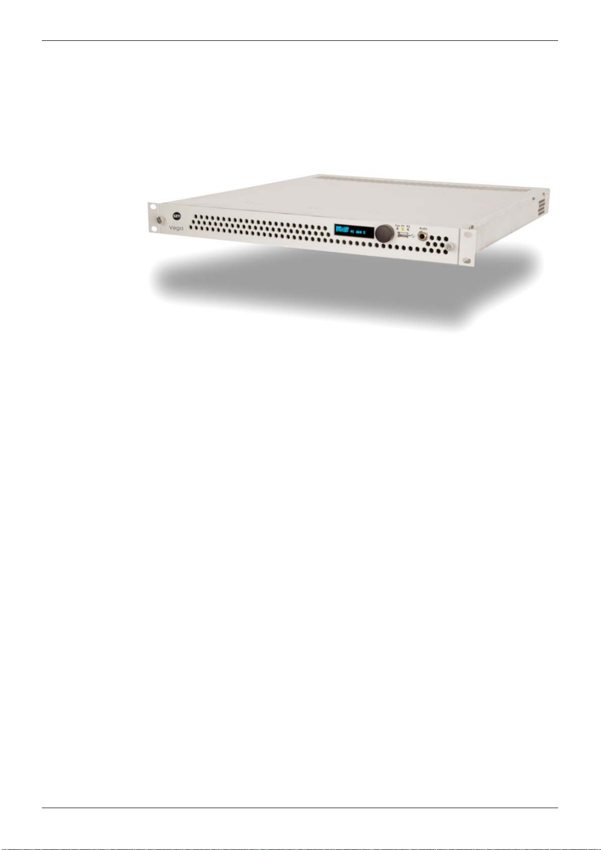
3 Product Introduction
Vega-MV is a family of compact 1RU video routers with integrated multiviewers for small and
medium scale applications. These are ideal for OB van and other space-restricted
installations.
Video routing is up to 32x32, with up to 32 video inputs and 32 outputs. The unit supports up
to 4K SDI video. Video inputs are auto-sensing for video sources.
All video inputs are visible on a dual-head multiviewer output. The unit is capable of driving up
to two quad-split multiviewer displays. Each display output comprises an HDMI output with an
copy SDI output.
The unit’s multiviewer features comprehensive alarm functions, audio metering and
monitoring capabilities.
Vega-MV also has a redundant/backup power supply option.
3.1 Application Areas
• OB-vans.
• Edit suites or studios.
• Other space-restricted installations.
Figure 1 Vega-MV Unit

Vega-MV Router Multiviewer - User Manual
Issue 1 Revision 2 Page 14 © 2017 SAM
Features Product Introduction 3.2
3.2 Features
• 1RU frame.
• Independent video routing for both SDI router outputs and multiviewer:
• Vega-16MV:Fixed 16 x 16 video router
with a second internal 16 x 16 crosspoint for multiviewer inputs.
• Vega-32MV:Fixed 32 x 32 video router
with a second internal 32 x 32 crosspoint for multiviewer inputs.
• Multi-definition capable inputs, up to 3G 1080p and 4K SDI.
Supports dual- and quad-link.
• Auto-sensing video inputs.
• Reference input for flicker-free and full frame operation.
• Control:
• SW-P-02 protocol
• SW-P-08 protocol
• RollCall Control Panel.
• Luna hardware control panels.
• Internal router and external router multiviewer modes.
• 8 character and 32 character source names supported.
• Switching of Router outputs and Multiviewer inputs:
• Independently controllable.
• Multiviewer ‘follow router destination’ mode.
• Single Multiviewer, dual-headed:
• Main outputs: 2-off 1.4a HDMI (up to 1920x1200p60).
• Copy outputs: 2-off Quad-link SDI 3G SDI (up to 1080p50/59/60).
• HDMI outputs support HDCP encrypted signals.
• Multiviewer On-Screen:
• Teletext subtitles display (WST on SD-SDI or OP-47 on HD-SDI).
• AFD decoding for adjusting the aspect ratio
• D-VITC and ancillary timecode decoding and display (SD-SDI/HD-SDI sources)
• Audio metering is supported for up to 32 mono channels per video display tile.
• Audio metering sourced from SD-SDI/HD-SDI/3G-SDI embedded audio groups
(PCM or *Dolby E metadata meter segment).
• Audio metering of Dolby E encoded audio from any SDI embedded audio pair. Up
to four Dolby E encoded pairs per SDI source. (Decoding of Dolby E audio
content is not supported.)
Important:
HDMI inputs/outputs support HDCP but this must be enabled from the Module menu,
Screens tab to display HDCP encrypted sources, see section 7.3.1.2.

Vega-MV Router Multiviewer - User Manual
Issue 1 Revision 2 Page 15 © 2017 SAM
Order Codes Product Introduction 3.3
• Alarms for video, audio and metadata,
with outputs to, GPI Outputs, LAN and/or SNMP traps
• Input standard decode available as on-screen caption.
• Assignable tallies
• Under Monitor Display (UMD) text entered via LAN or serial cable, supporting
TSL and other protocols, including SW-P-08.
• Clock display receiving time information via NTP network protocol or LTC
•Unit:
• Front panel mounted OLED display giving chassis and card status information.
• Intelligent fan speed control
• Power supply redundancy via optional external backup power supply.
• User-friendly set-up via browser software.
3.3 Order Codes
Order Code Description
Vega MV:
VEGA-16MV 1RU Vega-MV Router Multiviewer,
with 16 x 16 video router and dual-head multiviewer.
VEGA-32MV 1RU Vega-MV Router Multiviewer,
with 32 x 32 video router and dual-head multiviewer.
Other:
MV-EXTPSU3 1RU External Redundant/Backup Power Supply Shelf.
MV-1000PSU Power Supply Module
used in MV-EXTPSU3 and Vega-MV products.
Table 1 Vega-MV Order Codes

Vega-MV Router Multiviewer - User Manual
Issue 1 Revision 2 Page 16 © 2017 SAM
Vega-MV Inputs and Outputs Product Introduction 3.4
3.4 Vega-MV Inputs and Outputs
Figure 2 shows inputs and outputs of a Vega-16MV, which contains a 16 x 16 video router.
Vega-32MV is similar to Figure 2 but has 32 video inputs and outputs with a 32 x 32 router.
Figure 2 Vega-16MV I/O Diagram
Input/ Output Description
Router:
Video Inputs 1 to 16 Vega-16MV router and multiviewer video inputs.
Video Inputs 1 to 32 Vega-32MV router and multiviewer video inputs.
Video Outputs 1 to 16 Vega-16MV router video outputs.
Video Outputs 1 to 32 Vega-32MV router video outputs.
Multiviewer Display Outputs:
HDMI 1 and SDI copy Multiviewer display head 1:
• HDMI head output.
• plus quad-link SDI copy output.
HDMI 2 and SDI copy Multiviewer display head 2:
• HDMI head output.
• plus quad-link SDI copy output.
Table 2 Vega-MV Inputs and Outputs

Vega-MV Router Multiviewer - User Manual
Issue 1 Revision 2 Page 17 © 2017 SAM
Vega-MV Inputs and Outputs Product Introduction 3.4
Other:
LAN 1 Network connection for Router/Multiviewer.
This is the main network connection for the unit.
LAN 0 Network connection for NTP and for any firmware update
of the unit’s MV-NET card.
Serial Comms RS232/422 serial comms connection.
GPI/O GPI inputs and outputs.
Video Reference In Video reference input for the router multiviewer unit.
LTC In LTC input for the router multiviewer unit.
AC Mains AC mains power supply to Vega-MV.
DC Backup Supply Optional 24V DC backup supply to Vega-MV.
Input/ Output Description
Table 2 Vega-MV Inputs and Outputs (Continued)

Vega-MV Router Multiviewer - User Manual
Issue 1 Revision 2 Page 18 © 2017 SAM
Functional Description Product Introduction 3.5
3.5 Functional Description
The Vega-MV comprises a video router and a multiviewer. Figure 3 shows the system
architecture.
The video inputs and router outputs support video standards up to 4K. The video inputs form
both the router inputs and the multiviewer inputs.
Router Block:
The router block comprises an N x N router. The router is controllable from an external
controller or control panel.
MV Crosspoint Block:
The MV crosspoint block comprises an N x N crosspoint switch which permits a multiviewer
input to be connected to any Vega-MV video input. This allows the multiviewer to show the
same video source with different on-screen scaling or to follow a destination output of the
internal router.
Figure 3 Vega-MV Block Diagram

Vega-MV Router Multiviewer - User Manual
Issue 1 Revision 2 Page 19 © 2017 SAM
Functional Description Product Introduction 3.5
Multiviewer Block:
The multiviewer video inputs are routed from the Vega-MV video inputs via the MV Crosspoint
block. There are no separate controls for the MV crosspoint. SDI sources from any video
input can be assigned to any on-screen multiviewer tile.
The multiviewer inputs are processed by the multiviewer block. Video images are scaled and
other information is extracted, including audio levels, for display on the multiviewer display
outputs.
Video images are resized in scalers to form small images for video tiles; audio level and
status information is added and combined with some on-screen graphics to form the different
multiviewer display tiles. The tiles are arranged to form the final multiviewer display outputs.
Video sources can be layered in any order and any multiviewer input can be assigned onto
each display output.
There are two independent HDMI multiviewer display outputs (heads), each with a quad-link
SDI copy output.
LAN 1:
A network interface for control and media, for both the router and multiviewer blocks. It is also
used for firmware upgrades.
LAN 0:
A network interface for NTP connections. It is also used for firmware upgrades (upgrade of
Vega-MV’s MV-NET card only).
Network and Control:
The Network and Control block carries out the following functions:
• Passes video genlock information to the router and multiviewer.
• Passes LTC and NTP time information to the router and multiviewer.
• Controls the unit’s GPI/O ports.
• Controls the unit’s cooling fans.
• Interfaces to the unit’s front panel, including:
OLED display, control knob, status LEDs, USB port and headphones socket.

Vega-MV Router Multiviewer - User Manual
Issue 1 Revision 2 Page 20 © 2017 SAM
Functional Description Product Introduction 3.5
3.5.1 Vega-MV Components
A Vega-MV unit comprises various component parts. These are listed in Table 3 and shown in
Figure 4, which shows how the components are inter-connected.
Component Description
MV-NET “MV-NET”, Network and Control card
MV-NET Rear MV-NET rear panel (Part MV-NRP1)
MV-CTL “MV-CTL”, control and output card
MV-CTL Rear MV-CTL rear panel (Part MV-RMVCS8)
MV-VIP4 “VIP4”, 4K video input card
MV-VIP4 Rear VIP4 rear panel, 8x 4K inputs. (Part MV-RMVRO8)
Front Panel Vega-MV unit front panel
Fans Vega-MV unit fans, for ventilation
Midplane and Router All Vega-MV front cards and rear panel modules plug into a
midplane. The midplane houses a router block.
Table 3 Vega-MV Components
This manual suits for next models
1
Table of contents
Other Snell Switch manuals


Popular Switch manuals by other brands

Ascentic
Ascentic HLS-71 Series user manual

Cisco
Cisco WS C4224V 8FXS - 200Mbps Ethernet Switch Software configuration guide

Panasonic
Panasonic WH-0M1101A operating instructions

AETEK
AETEK H40-022-90-120-A Quick installation guide

Aurora
Aurora ASP-S123V user guide

Cisco
Cisco NMH Series Quick installation guide


