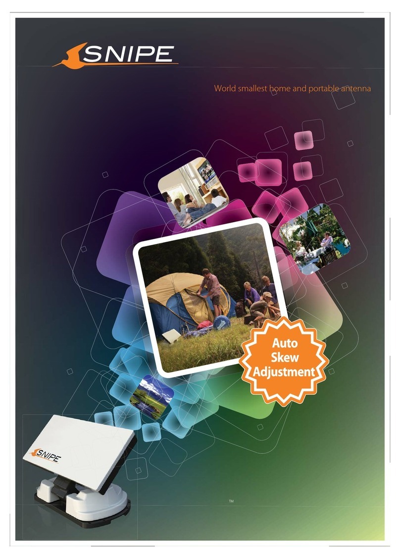
Snipe SELFSAT BT Grey Line User manual

ENGLISH : User’s manual
GERMAN: Bedienungsanleitung
FRENCH : Manuel utilisateur
ver 1.0
www.selfsat-service.de
www.selfsat.com
Automatic Flat Satellite Camping Antenna
SNIPE
CONNECT


Contents
1. General Information
.............................................................................................
...............................................................................
.............................................................................................
1-1. Introduction
1-2. Proper use and operation
1-3. Safety notes
2
2
3
2. Contents
.......................................................................................
...........................................................................................
2-1. Accessory included
2-2. Name of parts
4
5
9. Caravan/Motorhome Installation
.................................................................
..............................................................................
..............................................................................
9-1. Required space for SNIPE BT Grey Line
9-2. Equipment for installation
9-3. Instruction for installation
16
17
17
3. Operating Instruction
....................................................................................3-1. Connection diagram 7
5. Functional description of mobile app ............................................... 11
...................................................................................
.................................................................
.........................................................................................
4-1. Searching the satellite
4-2. Back to HOME position & Turning off
4-3. Special function
8
8
9
...............................................................................................
............................................................................................
8-1. Dimension
8-2. Specifications
15
15
4. Functional description
6. Firmware Update
7. Troubleshooting
8. Specifications
13
14
...............................................................................
................................................................................

ENGLISH - 2
1. General Information
•
•
•
•
•
•
•
Please also note the following instructions from the manufacturer :
1-1. Introduction
These instructions describe the functions and operation of SNIPE BT Grey Line, auto skew
satellite system.
Correct and safe operation of the system can only be ensured by following instruction, both
for installation and operation.
SNIPE BT Grey Line is an intelligent satellite-TV reception system which can align itself towards
a preset satellite automatically as long as the system is located within the footprint of the
selected satellite.
SNIPE BT Grey Line only occupies requisite space while it performs the necessary adjustments
with slim and agile antenna body.
For general operation, please ensure that the system always has a clear view to the sky. In
Europe, all satellites are in an approximate position on the equator. If the satellite‘s signal
beam is interrupted by obstacles such as mountains, buildings or trees, the unit will not
function and no TV signal will be received.
For more information on general use of this unit consult local dealer for assistance.
1-2. Proper use and operation
This product has been designed for portable use and fixed installation on vehicles with
maximum speeds of 130 km/h. The unit is programmed to automatically aims at geostationary
television satellites.
The power is supplied by a standard vehicle electrical system with a rated voltage of 12 Volts
DC. For installations on the vehicle, use power input cable (cigarette lighter adaptor) to
supply power. For portable use, optional power adaptor produced by manufacturer must be
used.
Use of the equipment for any other purpose to the one specified is not permitted.
It is not possible to add or remove components on this product.
The use of other components other than those originally supplied is not permitted.
To complete installation, installer must strictly follow instruction in the supplied user manual.
Failure to follow the user manual may cause damage to the unit or user's vehicle.
The product does not require any regular maintenance; all service must be carried out at
approved service centers.
All relevant guidelines of the automotive industry must be observed and complied with.
The equipment must only be installed on solid vehicle roofs.
Avoid cleaning user's vehicle with the mounted satellite system in a drive-through car wash or
a car wash with a high-pressure cleaner.

ENGLISH - 3
1-3. Safety notes
CE Certicate Note
Please carefully read and follow the operating instructions in this manual and use the
SNIPE BT Grey Line for its intended purpose.
Upon installation of SNIPE BT Grey Line, please ensure the installation is done with
supplied cables and ensure the cables are not modified in any way.
As the user of this equipment, be responsible for ensuring compliance with the relevant
laws and regulations.
The manufacturer does not take liability for direct or indirect consequential damage of
the system, motor vehicles or other equipment by reason of unsuitable battery usage or
erroneous installation or wrong wire connection.
We hereby declare, that all major safety requirements, concerning to
CE Mark Directive (93/68/EEC) and Low Voltage Directive (73/23/EEC),
Electromagnetic Compatibility Directives (89/336/EEC, 92/31/EEC) and
Directive 2014/30/EU are fulfilled, as laid out in the guideline set down by
the member states of the EEC Commission.
The full CE Declaration of Conformity document you can download at
https://www.selfsat-service.de/ce-documents

ENGLISH - 4
2. Contents
2-1. Accessory included
The images used in this manual are for illustrative purposes and may differ from
the actual ones.
Specifications and appearance of this product are subject to change without prior
notice for quality improvement.
The unit enables to have power from car battery. To make power input cable for
direct connection, cut off cigarette lighter adaptor and peel off to take copper
cables out.
Only power adaptor produced by SNIPE series manufacturer is guaranteed and
has to be used.
Optional parts are purchased separately. Please ask to local dealer/shop for more
information.
※
※
※
※
※
Main unit Mounting plate
Allen wrenchCable holder, Cable gland
Power input cable
(Cigarette lighter adaptor)
Signal cable
(x2 for optional twin outputs)
Screw set
M6 × 15 (8), M4 × 20(14)
User manual Power adaptor
(Optional)
BT Remote control
(Optional)
Manual
Controller Controller bracket,
Rear cable cover
Controller cable
Base pads
STB cable - 1.5m

ENGLISH - 5
2-2. Name of parts
Main unit
Latch
Antenna
Elevation
Main body
Base
Mounting plate
LNB
Skew pivot
to Controller cable connection
(pre-connected)
to STB (optional)
to Controller ("ANT" port)
Controller
• Front
• Back
OnLED Indicator
Power S/W
USB port
Controller bracket hole
HOME LED
Lock LED
DiSEqC LED
Satellite LEDs
DiSEqC button
HOME button
Arrow buttons
SET button
BlinkingOff
STB cable to STB
Signal cable from Main unit
Dip switch (Mode selector) Controller cable from Main unit
Power port
Note : For normal operation, Dip switches in MODE should be up

ENGLISH - 6
Display screen
BT button
(RCU) OFF
HOME button
SET/ON button
Arrow button
DiSEqC button
Bracket
Pairing antennas
with remote controls
Turn off
the remote control
Remote control : BT Remote control (separate purchase)
Remote control : Mobile application
SET/ON button
When using the remote control, press this button to
activate the remote control.
It is used to confirm the selected menu with the same
button as the SET button on the controller.
(RCU) OFF
Used to turn off the remote control immediately.
Even if do not press this button, the screen turns off
if do not use the remote control for more than 10 seconds.
To use it again, press the SET/ON button.
BT button
Button for pairing the antenna and BT Remote control.
HOME button
Move the antenna to the HOME position.
◀, ▶ (Arrow) button
Select the desired menu with the arrow buttons. Same as
the arrow buttons on the controller.
DiSEqC button
Turn on/off the DiSEqC function.
[D] is displayed at the screen when the DiSEqC function is
activated.
Using the remote control app, operate the antenna,
change the satellites to receive, and even update the
firmware if necessary.
Download the "SNIPE CONNECT" app from the App Store
(Android/iOS).
In order to operate SNIPE BT Grey line using the app, the
antenna must be paired with the "SNIPE CONNECT" app.
Android QR CODE iOS QR CODE
RCU

ENGLISH - 7
3. Operating Instruction
3-1. Connection diagram
Portable use
Attach four(4) base pads to the bottom of antenna base.
CONTROLLER
MAIN UNIT
Controller cable (20pin cable)
※Extra connection
for twin outputs
(optional)
Signal cable
There are two cable connections from the main unit to the controller
Use controller cable (20pin) to connect the controller and the cable running out from the main unit
Use STB cable (the shortest cable) to connect the controller and STB
Please check the labels to use the correct cable for the job
Please ensure the provided cables are used and not modified in anyway
•
•
•
•
•
Power input cable
Signal cable (7m)
Receiver/STB TV
Ignition
Cigar jack
STB cable (1.5m)
Receiver/STB
TV

ENGLISH - 8
4. Functional description
4-1. Searching the satellite
Mode selector is for A/S, so it is not recommended by consumers to modify it arbitrarily.
Consumers should never do this, and if trouble is occurred in Manual mode, guarantee
will not be provided.
Warning
※Get ready to use
a.
b.
c.
d.
e.
f.
When the controller is turned on, some LEDs light indicate firmware version
(It is made by binary code and for future service purpose)
Once the unit is ready to use, one of satellite LED is lit ON at default satellite
Go to the target satellite using arrows buttons and press SET button to confirm
Before satellite search, HOME LED blinks for antenna status(position) check
(If antenna was not at HOME, antenna has to return to HOME first, LED may blink for a while)
Lock LED blinks during satellite search and becomes solid when the target satellite is found
After use and before travelling, press HOME button for HOME positioning
Default is set Automatic mode;
both dip switches are up.
Customers should use only in
Automatic mode.
If the switch is handled in other
than the Automatic mode, the
unit does not operate normally.
4-2. Back to HOME position & Turning o
In some cases, the antenna is automatically stopped and sent to HOME position
A. Automatic
a. If ignition cable is connected and ignition signal is detected
antenna position check (●
●
)
searching satellite (
●
)/ found (●)
firmware ver. (Binary code)
Automatic mode
Manual mode

ENGLISH - 9
The DiSEqC function is not activated when the antenna is in the home position.
After moving the antenna to another position, press the SET button to activate
the DiSEqC function.
NOTE
A. DiSEqC setting
After use and before travelling, the antenna has to be sent to HOME manually
B. Manual
Refer SNIPE BT Grey Line’s pre-satellites for DiSEqC 1.1 when user setup at STB
a.
b.
After use and before travelling, press HOME button to return the antenna back to HOME position and
the unit is automatically turned off in 30 seconds
HOME LED blinks during HOME positioning and becomes solid when the antenna is at HOME
For example :
1
2
3
4
5
6
7
8
9
10
11
12
LNB 1
LNB 2
LNB 3
LNB 4
LNB 5
LNB 6
LNB 7
LNB 8
LNB 9
LNB 10
LNB 11
LNB 12
ASTRA 1
HOTBIRD
ASTRA 3
ASTRA 2
EUTELSAT 5W
THOR
ASTRA 4
HISPASAT
TURKSAT
EUTELSAT 9
USER1
USER2
NO LNB Satellite
4-3. Special function
a. Default setting for DiSEqC is OFF, DiSEqC LED is off
b.
c.
To switch the function ON/OFF, make sure that antenna is at HOME and press DiSEqC button for
DiSEqC can be executed after pressing 2 seconds (See also DiSEqC LED status changes between ON
and OFF)
For DiSEqC operating, user needs to assign DiSEqC satellites list at STB is in same order as above SNIPE
BT Grey Line’s pre-set list
DiSEqC On(●) / Off(○)

ENGLISH - 10
Manual setting of GPS location is an option for instant satellite search,
the antenna will search satellite based on GPS data after GPS is received.
NOTE
In case, antenna takes long time to search a satellite, there is the extra option of location
setting for GPS.
B. GPS location manual setting
-
-
ON
DiSEqC LED
All LED OFF
-
ON
-
Lock LED
ON
-
-
HOME LED
Germany
France
Netherland
Italy
Turksat
ASTRA2
ASTRA3
ASTRA1
Hot Bird
Etelsat 9
ASTRA 4
Thor
Eutelsat 5W
Hispasat
USER1
USER
Germany France Netherland Italy
Aachen
Augsburg
Bad Homburg
Bamberg
Berlin
Chemnitz
Gottingen
Hamburg
Munster
Offenburg
Passau
Neubrandenburg
Bayonne
Brest
Caen
Calais
Colmar
Nantes
Nizza
Paris
Saint-Étienne
Dijon
Toulouse
Limoges
Alkmar
Apeldoorn
Enschede
Groningen
Hoogeveen
Leeuwarden
Nijmegen
Roermond
Rotterdam
Tilburg
Utrecht
Emmeloord
Barletta
Bolzano
Cagliai
Carpi
Catania
Lecce
Livorno
Milano
Napoli
Pesaro
Pescara
Roma
Country
a.
b.
Press and hold DiSEqC button then turn on the controller
Select the country from available options (four(4) countries) using DiSEqC/HOME buttons to change
and confirm with controller LED ON as below table
d.
e.
f.
Once location setting is finished, press SET button to save
LEDs become off and controller will be automatically turned off
At next turn on, the antenna finds satellite with saved information
c. Select the city from available options using arrow buttons to change and confirm with LED ON as
below table
Country indication
City indication

ENGLISH - 11
5. Functional description of mobile app
3-1. Connection diagram
1
3
2
Download the SNIPE CONNECT app from the App store (Android/iOS).
Can check the app version on the app screen.
Check the MAC Address at your antenna unit (on the controller or
Usermanual).
When you run the downloaded application, a connectable antenna
unit is automatically.
Select the one that matches your antenna MAC Address.
(The MAC address of SNIPE BT Grey line is TA-XX:XX:XX )
Click the 'connect' button to complete BT connection between your
antenna.
1.
2.
3.
4.
Before using this app, need to
activate BT and GPS function on
your smart device.
Pairing the antenna with App
Android QR CODE iOS QR CODE

ENGLISH - 12
Go to the settings page where can configure settings for the app.
Setting button
Indicates the current status of the antenna.
Status display window
Select a satellite to search. The pre-programmed satellite is ASTRA1,
which can be changed to the desired satellite via the APP.
Satellite selection window
Select the desired satellite and press the button, the antenna will search
for it. While searching for a satellite, the orange lamp flashes, and when
a satellite is found, the green lamp lights up.
Used to searching satellites
Used to update the antenna firmware and satellite information
Do not close application or power off the antenna while the update is
in progress.
The update will take approximately 5-10 minutes.
F/W Update
The orange lamp blink while the antenna moves to the HOME position,
and the green lamp turns on after it has completely moved to the
HOME position.
Used to move the antenna to the HOME position
When DiSEqC is set, the orange lamp turns on and supports DiSEqC in
the set-top box.
Used to set DiSEqC support of set-top box.
Check the firmware version of the antenna and mobile app.
Can delete the MAC address of a registered product.
To register a new product, return to the available devices .
Can change the language of the app to the language you use.
Setting page
4
5

ENGLISH - 13
6. Firmware Update
※USB 2.0 standard has to be only used for update
※Use FAT32 format USB only
NOTE
Transfer firmware program to a USB root folder (not belonging to any other folder) in an empty USB
i.
ii.
1.
Once update is completed, controller starts to reboot5.
Ensure that the unit is turned off and plug the USB into USB port of controller
Press and hold SET button then turn on the power
During upgrade process, satellite LEDs are lit in sequence
2.
3.
4.
Please go to website www.selfsat.com to download update program (firmware)
In case a controller does not recognize the USB drive, take the USB out and plug into a PC.
Right click USB folder, go to “Properties” and check if the “File system” is FAT32.
If not, right click USB folder again, go to “Format” and re-setup a file system to FAT32
CONTROLLER
For example :
Power input cable
USB

ENGLISH - 14
7. Troubleshooting
There are a number of common issues that can affect the signal reception quality or
the operation of the unit. The following sections address these issues and potential
solutions
i.
Connection between the power and controller.
Connection between the controller and antenna. Make sure that the left port of the antenna should be
connected to the controller.
Check if the power input cable has been damaged.
Check the battery polarities (+/-).
ii.
iii.
Select another satellite as example Astra3, if this locks then select your desired satellite.
Turn the unit off and then back on again and select desired satellite.
ii.
iii.
-
-
-
-
A. No function when power on the controller
Check again all the cable connections have been made correctly.
C. Mechanical problems
i.
Try to power OFF/ON again.
If the antenna does not move into desired position.
ii.
Try to power OFF/ON again. If problem persists, please contact local dealer/shop for assistance.
If the antenna makes a noise whilst remaining static.
i.
B. Fail to search the selected satellite
Satellite signals can be blocked or degraded by buildings, trees.
Make sure there are no obstructions in a southward direction.
i.
D. Other issues
If the system has been improperly wired, it will not operate properly. Contact local
dealer/shop for assistance of cable damage.

ENGLISH - 15
8. Specications
8-1. Dimension
Input Satellite Frequency
Polarization
Antenna Gain
Size ( W x D x H )
Weight
Min EIRP
Angle Range (Elevation , Azimuth , Skew)
Satellite Searching Time
Output
LNB Output Frequency
L.O. Frequency
Operating Temperature
Input Voltage
Power Consumption
10.7 ~ 12.75 GHz
Vertical & Horizontal
33.7 dBi @ 12.7 GHz
515 × 355 × 201 mm
10.3 kg
50 dBW
15° ~ 90° , 360° , -45° ~ +45°
120 seconds (AVG)
1 / 2 output (Optional)
950 ~ 2,150 MHz
9.75 / 10.6 GHz
-30 °C ~ +60 °C
DC 12 V
30 W (in searching)
454mm
515mm
316mm
355mm
MAX 426mm
MIN 201mm
126mm
201mm
8-2. Specications

ENGLISH - 16
9. Caravan/Motorhome Installation
Please allow that there is enough space around SNIPE BT Grey Line for flat antenna section
to complete a full 360° scan of the sky and return to the HOME position
9-1. Required space for SNIPE BT Grey Line
Driving direction
Driving direction
Vehicle rear
B : Radius 32cm
up to a height 19.4cm
A : Radius 22.5cm
up to a height 12.9cm
Center of
the rotation unit
51.5cm
17.8cm
33.8cm
37.5cm
20.1cm
19.6cm
12.9cm
16.9cm

ENGLISH - 17
※ Mounting plate direction
Silicone
Signal cable (7m)
Allen wrench
Controller bracket, Rear cable cover
Controller cable (7m)
Controller
STB cable (1.5m)
Masking tape
M6 × 15(8), M4 × 20(14)
Mounting plate
Power input cable (Cigarette lighter adaptor)
Cleaner
Power drill
2mm drill bit, over 25mm drill bit
Cable holder & gland
9-2. Equipment for installation
9-3. Instruction for installation
A. Mounting plate installation on a vehicle roof
1
3
2
7
8
11
12
1
2
3
4
5
6
7
8
9
10
11
12
13
14
15
9
13
14
15
Put aside the mounting plate to apply silicone
within the attached tape line but leave 2cm
inward gap from the line
Attach masking tape outside of the mounting
plate by 5mm away from the plate edges
A-4
A-2
FRONT
Clean the surface with cleaner
A-3
A-1
Locate mounting plate in the center of the
vehicle roof
5
10
Driving direction
6
4

ENGLISH - 18
B-3
B-1
Apply silicone on the holes
C. Apply silicone between mounting plate and masking tape
Remove masking tape and allow to dry
C-4
C-2
Apply silicone around mounting plate edges
C-3
C-1
Tidy silicone surface
Place the antenna on the mounting plate
according to the Mounting plate direction
B. Assemble 7pcs of M4x20 bolt to fix the mounting plate
Assemble seven(7) of M4x20 screw Re-apply silicone to cover bolts assembled
B-4
B-2
Place the mounting plate on the silicone and
make 7 holes (2mm) with a power drill
Table of contents
Languages:
Other Snipe Antenna manuals
Popular Antenna manuals by other brands
Antares
Antares ANTARION G6+ CONNECT installation manual
Vivax Metrotech
Vivax Metrotech vLoc3 Series user guide
KVH Industries
KVH Industries Ka Tri-Americas LNB installation manual
Ebyte
Ebyte TXWF-XPL-150 user manual

Ubiquiti
Ubiquiti RocketDish RD-5G30 quick start guide
Megasat
Megasat DVB-T 20 user manual
