Sno-Way 24 Series User manual

OWNER’S
MANUAL
24 SERIES SNOW PLOW
25 SERIES SNOW PLOW
WITH
DOWN PRESSURE SYSTEM
FOR PLOW SERIAL NUMBERS AFTER
24D100000
25D100000
97100200E
PRODUCTS
TM


1
TABLE OF CONTENTS
INTRODUCTION........................................................................................................ 2
SAFETY ...................................................................................................................... 3
THEORY OF OPERATION......................................................................................... 4
PLOWING OPERATION............................................................................................. 7
Operating Classes ............................................................................................ 7
Before The Season Begins .............................................................................. 7
Transporting Vehicle With Plow Attached...................................................... 7
Plowing Like A Pro ........................................................................................... 8
Using The Down Pressure (DP) Hydraulic System........................................ 8
Clearing Driveways........................................................................................... 8
Clearing Parking Lots....................................................................................... 9
Mounting Snow Plow To Vehicle ..................................................................... 9
Installing The Transport Lock Clamp............................................................ 10
Removing Snow Plow From Vehicle ............................................................. 11
TROUBLE SHOOTING GUIDE................................................................................ 13
MAINTENANCE....................................................................................................... 18
General ............................................................................................................ 18
Break In Period................................................................................................ 18
Periodic Inspection......................................................................................... 18
Hydraulic Cylinders........................................................................................ 18
Electrical Quick Disconnect Plug.................................................................. 18
Polycarbonate Blade Care ............................................................................. 19
Service Intervals ............................................................................................. 19
Fluid Requirements ........................................................................................ 19
Changing Oil and Cleaning Filter Screen..................................................... 19
Disk Shoe Adjustment.................................................................................... 22
Cutting Edge ................................................................................................... 22
Trip Spring Adjustment.................................................................................. 23
TORQUE SPECIFICATIONS.................................................................................... 24
HYDRAULIC SCHEMATIC (Down Pressure System) ........................................... 25
WIRING SCHEMATIC ROCKER SWITCH STYLE (Down Pressure System)....... 26
WIRING SCHEMATIC JOY STICK STYLE (Down Pressure System)................... 27
WARRANTY............................................................................................................. 29
TABLE OF CONTENTS
Page

2
INTRODUCTION
This manual was written for the assembly, installation and
maintenance of your new Sno-Way Plow. Most
importantly, this manual provides an operating plan for
safe use. Refer to the Table of Contents for an outline of
this manual.
Please keep this manual with your machine at all times as
reference material and so it can be passed on to the next
owner if the machine is sold.
We require that you read and understand the contents of
this manual COMPLETELY, especially the chapter on
SAFETY, before attempting any procedure contained in
this manual.
The Society of Automotive Engineers has adopted
this SAFETY ALERT SYMBOL to pinpoint character-
istics that, if NOT carefully followed, can create a
safety hazard. When you see this symbol in this man-
ual or on the machine itself, BE ALERT!, your per-
sonal safety and the safety of others, is involved.
• Defined in the next column, are the SAFETY ALERT
messages and how they will appear in this manual.
NOTE: Additional information concerning the equipment
or the procedure that may or may not be contained
elsewhere in this manual.
BE AWARE! It is illegal to remove, deface or other-
wise alter the safety decals mounted on this equip-
ment.
Record the Power Pack Model Number, Power Pack
Serial Number, Controller Serial Number, Blade Model
Number, Blade Serial Number And The Pump Serial
WARNING
FAILURE TO HEED CAN RESULT IN SERIOUS
INJURY OR DEATH.
CAUTION
Information, that if not carefully followed, can
cause minor injury or damage to equipment!
Number in the space provided below as a handy record
for quick reference. The Power Pack Serial Number is
located on the A-Frame of the Power Pack, the blade
serial number is located on one of the middle ribs of the
blade. This plate contains information that your Dealer
needs to answer questions or to order replacement parts,
if needed, for your unit.
We reserve the right to make changes or improve the
design or construction of any part(s) without incurring the
obligation to install such parts or make any changes on
any unit previously delivered.
Sno-Way snow plow Service Parts Manuals are available
for purchase from your authorized Sno-Way dealer.
Sno-Way snow plow Service Parts Manuals may also be
ordered from the address on the back of this manual by
requesting part number 97100204.
DEALER
NAME
PHONE ( ) –
ADDRESS
CITY STATE ZIP
(FILL IN)
ORIGINAL PURCHASER
NAME
PHONE ( ) –
ADDRESS
CITY STATE ZIP
(FILL IN)
NAME PLATE DATA
POWER PACK MODEL NUMBER
BLADE SERIAL NUMBER
PUMP SERIAL NUMBER
(FILL IN)
POWER PACK SERIAL NUMBER
CONTROLLER SERIAL NUMBER
BLADE MODEL NUMBER
(Located on Blade Frame)
(Located on A-Frame of Power Pack)

SAFETY
BEFORE ATTEMPTING ANY PROCEDURE IN THIS
BOOK, READ AND UNDERSTAND ALL THE SAFETY
INFORMATION CONTAINED IN THIS SECTION. IN
ADDITION, ENSURE ALL INDIVIDUALS WORKING
WITH YOU ARE ALSO FAMILIAR WITH THESE
SAFETY PRECAUTIONS.
For your safety Warning and Information Decals have
been placed on this product to remind the operator
to take safety precautions. It is important that these
decals are in place and are legible before operation
begins. New decals can be obtained from Sno-Way or
your local dealer.
REMEMBER The careful operator is the best
operator. Most accidents are caused by human error.
Certain precautions must be observed to prevent the
possibility of injury to operator or bystanders and/or
damage to equipment.
NEVER operate Plow when under the influence of
alcohol, drugs or other medications that could hamper
your judgement and reactions. An accident may result in
serious injury or death to other persons or yourself.
ALWAYS operate vehicle in a well-ventilated area. The
carbon monoxide in exhaust gas is highly toxic and can
cause serious injury or death.
NEVER allow hands, hair or clothing to get near any
moving parts such as fan blades, belts and pulleys. Never
wear neckties or loose clothing when working on the
vehicle.
NEVER
wear wrist watches, rings or other jewelry when
working on the vehicle or individual equipment. These
things can catch on moving parts or cause an electrical
short circuit that could result in serious personal injury.
ALWAYS wear safety goggles when working on the
vehicle to protect your eyes from battery acid, gasoline,
and dust or dirt from flying off of moving engine parts.
ALWAYS be aware of and avoid contact with hot
surfaces such as engine, radiator, and hoses.
ALWAYS wear safety glasses with side shields when
striking metal against metal! In addition, it is
recommended that a softer (non-chipable) metal material
be used to cushion the blow. Failure to heed could result
in serious injury to the eye(s) or other parts of the body.
NEVER allow children or unauthorized person to
operate this unit.
NEVER exceed 45 m.p.h. when snow plow is attached
to vehicle. Braking distances may be reduced and
handling characteristics may be impaired at speeds
above 45 m.p.h.
ALWAYS lock the vehicle when unattended to prevent
unauthorized operation of the plow.
ALWAYS check the job site for terrain hazards,
obstructions and people.
NEVER exceed 10 m.p.h. when plowing. Excessive
speed may cause serious injury and damage of
equipment and property if an unseen obstacle is
encountered while plowing.
ALWAYS position blade so it does not block path of
headlamps beam. Do not change blade positions while
traveling. An incorrect plow position blocking headlamp
beam may result in an accident.
ALWAYS check surrounding area for hazardous
obstacles before operating this unit.
ALWAYS inspect the unit periodically for defects. Parts
that are broken, missing or plainly worn must be replaced
immediately. The unit, or any part of it should not be
altered without prior written approval of the manufacturer.
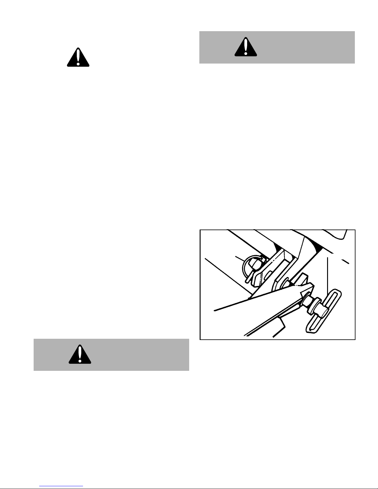
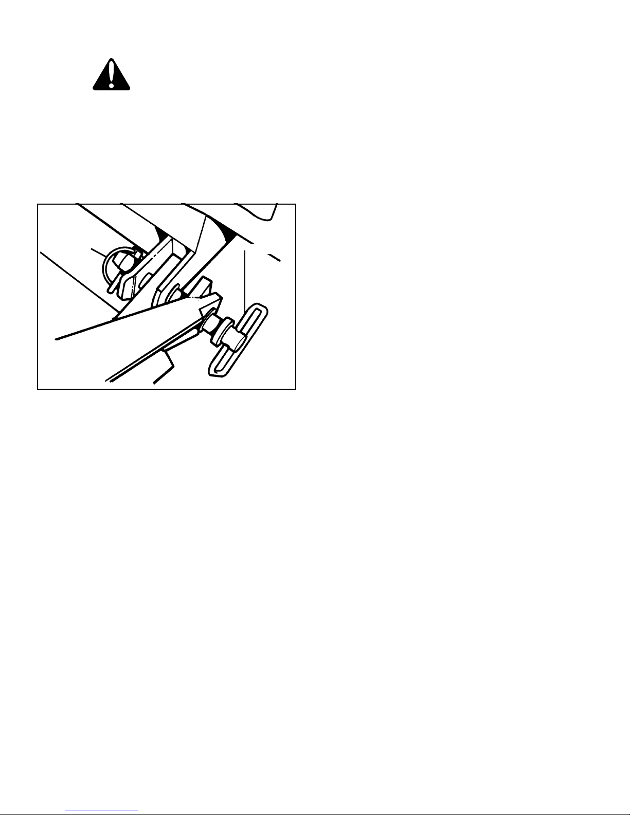
ALWAYS insert the cylinder lock when plow is not in
use. If the cylinder lock is not installed, the plow blade
could inadvertently drop and cause serious injury.
ALWAYS shut off the vehicle engine, place the
transmission in Neutral or Park, turn the ignition switch to
the “OFF” position and firmly apply the parking brake of
the vehicle before attaching or detaching the blade from
the vehicle or when making adjustments to the blade.
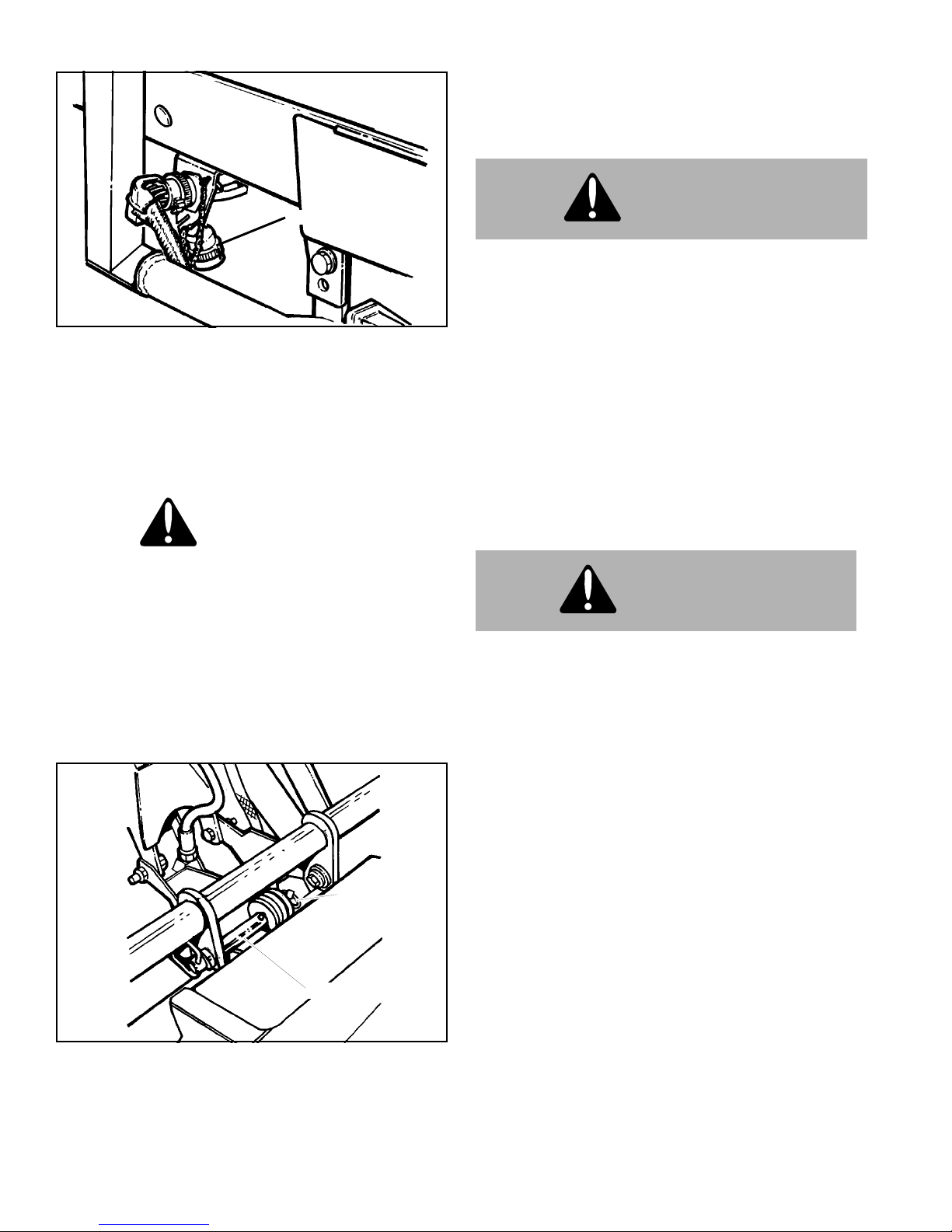
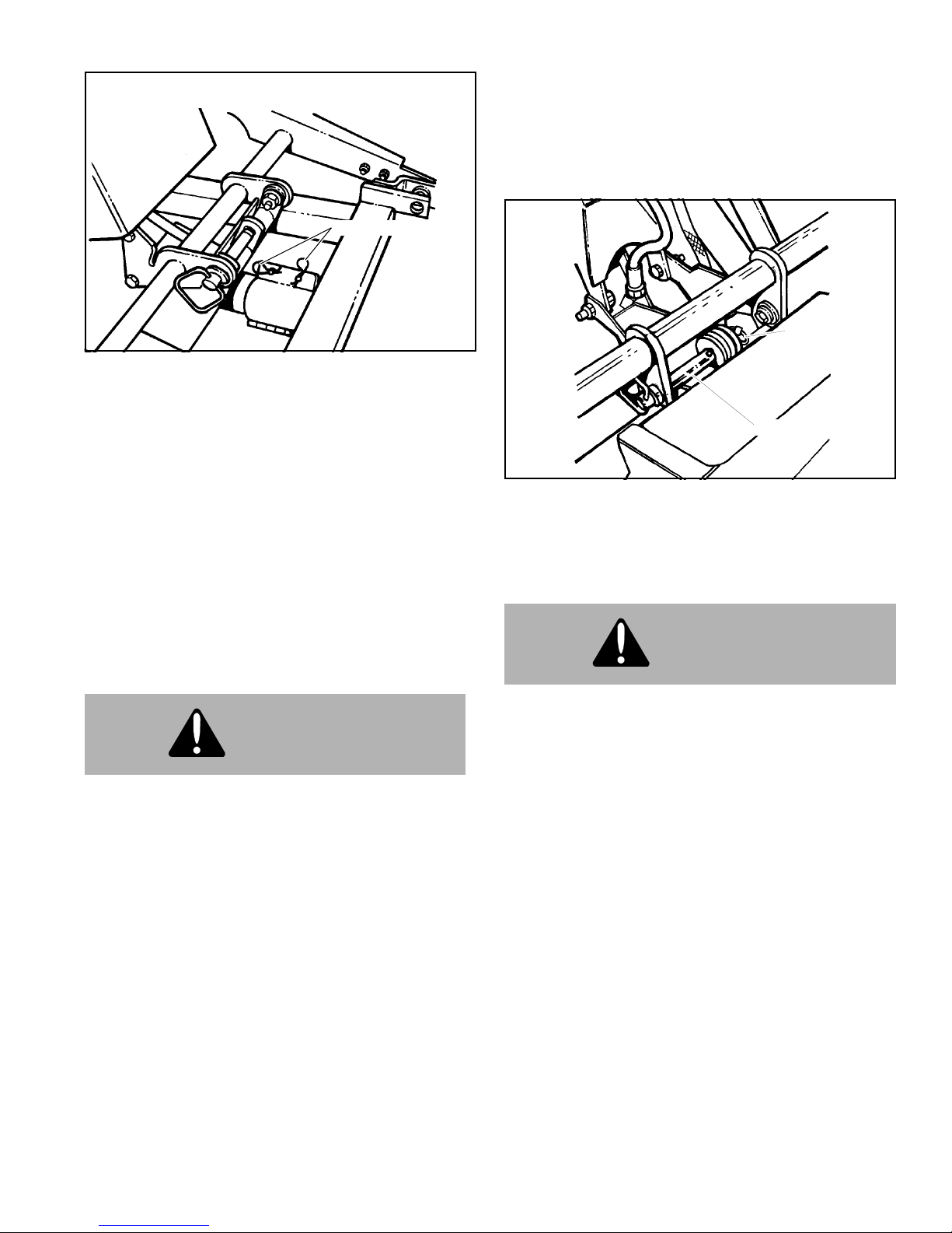
ALWAYS inspect lift system bolts and pins whenever
attaching or detaching the plow, and before traveling.
Worn or damaged components could result in the plow
dropping to the pavement while driving, causing an
accident.
ALWAYS keep hands and feet clear of blade and
A-Frame when attaching or detaching plow.
NEVER place fingers in A-frame or mount lug holes to
check alignment when attaching snow plow. Sudden
motion of the plow could severely injure a finger.
NEVER stand between the vehicle and blade or directly
in front of blade when it is being raised, lowered or
angled. Clearance between vehicle and blade decreases
as blade is operated and serious injury or death can
result from blade striking a body or dropping on hands or
feet.
NEVER work on the vehicle without having a fully
serviced fire extinguisher available. A 5 lb or larger CO2
or dry chemical unit specified for gasoline, chemical or
electrical fires, is recommended.
NEVER smoke while working on the vehicle. Gasoline
and battery acid vapors are extremely flammable and
explosive.
NEVER use your hands to search for hydraulic fluid
leaks; escaping fluid under pressure can be invisible and
can penetrate the skin and cause a serious injury! If any
fluid is injected into the skin, see a doctor at once!
Injected fluid MUST BE surgically removed by a doctor
familiar with this type of injury or gangrene may result.
REMEMBER it is the owner’s responsibility for
communicating information on the safe use and
proper maintenance of this machine.
3

4
Hydraulic Power Unit
The hydraulic power unit consists of:
• 12VDC Motor
• Hydraulic Pump rated at 1.03 GPM @ 1400 PSI
• 1 quart capacity Reservoir
• fine mesh IntakeFilter
• Magnet
The fluid supply line for the pump is submerged in the
Reservoir and is equipped with a fine mesh Intake Filter.
Further protection of the Hydraulic system is provided by
a Magnet located in the Sump.
The 12VDC Motor is protected electrically by 150A Circuit
Breaker located between the vehicle battery and the
Motor Solenoid.
The Hydraulic Pump is protected by a 1750 psi System
Relief Valve.
This unit is equipped with a DOWN PRESSURE OPTION
that allows the operator to selectively switch the system to
provide additional Hydraulic force to the lowering of the
plow.
IMPORTANT: The electric coils, which operate the
solenoid valves, require a minimum of 9-1/2 volts DC
for proper operation. Lower Voltage will cause erratic
operation, or failure to operate.
Hydraulic Controls
The Hydraulic Controls consists of:
• One dual solenoid, spring centered, three position
Angle Valve
• Two Crossover Relief Valves, 2000 psi
• System Pressure Relief Valve, 1750 psi
•Onesinglesolenoid,springreturn,twopositionLower
Valve
• One system Check Valve
• Two single acting Angle Cylinders, right and left
• One double acting Raise Cylinder
• One single solenoid, two position, spring return,
4-Way Valve
• Down Pressure (DP) Relief Valve
Raise Mode Of Operation
Electrical current is provided to the Raise/Lower Switch
center terminals (common) through the 9 RED/BLK wire,
any time the vehicle key switch is in the ACC or RUN
position.
The Raise/Lower Switch is a three position,
ON-OFF-MOMENTARY ON switch. The switch will
automatically return to OFF from the Raise ON position,
and will lock in the Lower/Float ON position until cancelled
by the operator.
Activating the Raise Switch establishes a circuit allowing
current to flow through the Raise/Lower Switch to the
Motor Solenoid primary circuit, through the 10 BROWN
wire, which activates the Motor Solenoid.
Activating the Motor Solenoid closes the secondary
contacts allowing current to pass from the vehicle battery,
through the 2B RED wire and the 150A Circuit Breaker, to
the 12VDC Motor. The 12VDC Motor is direct coupled to
the Hydraulic Pump.
Hydraulic fluid, under pressure, is directed to the Angle
Valve. If the Angle Switch is not activated the Angle Valve
will be in the Neutral, centered, position and fluid will flow
through the Angle Valve, Check Valve, and to the 4-Way
Valve. If the DP Switch is not energized the fluid will flow
through the 4-Way valve to the base end of the Raise
Cylinder. Pressurizing the base end of the Raise Cylinder
will cause the cylinder rod to extend and lift the Plow.
The raise circuit is protected by the System Pressure
Relief Valve set to relieve system pressure at
approximately 1750 PSI.
Releasing the Raise Switch de-energizes Motor Solenoid
interrupting current to the 12 VDC Motor. The Plow will
remain in the raised position until the Lower Switch is
activated.
NOTE: If the Raise/Lower Switch is initially in the
Lower/Float position actuating the Raise side of the
switch will also break the circuit to the Lower Solenoid,
which allows the Lower Valve to shift, under spring
pressure, to the blocked port position.
Lower Mode Of Operation
Electrical current is provided to the Raise/Lower Switch
center terminals (common) through the 9 RED/BLK wire,
any time the vehicle key switch is in the ACC or RUN
position.
Activating the Lower Switch allows current to flow through
the Raise/Lower Switch to the Lower Solenoid, through
the 7 BLK wire. The Lower Solenoid shifts the Lower
Valve to the open port position which establishes a flow
path from the base end of the Raise Cylinder to the sump.
This lowers the plow and establishes a float circuit. The
float circuit allows fluid to exit the Raise Cylinder allowing
the plow to follow the contours of the ground.
THEORY OF OPERATION

5
IMPORTANT: The lower valve is closed by spring
pressure. If it does not close completely against the
valve seat, the plow can slowly lower after the raise
switch is released. If this occurs, cycle the plow
through a raise and lower cycle a few times to flush
out anything that may be between the valve and seat,
this also allows the valve and valve seat to mate and
seal.
Down Pressure (DP) System
The Down Pressure (DP) System consists of two
separate but interactive electrical circuits, both controlled
by the DP Toggle Switch.
•4-WayValve-ControlsfluidflowtoandfromtheRaise
Cylinder and establishes either a float or DP
condition.
• DP Pressure Switch - a pressure sensitive ON switch
that controls the pressure available to the DP
system by limiting the Motor run time in the DP
mode.
Electrical current is provided to the DP Toggle Switch
center terminals (common) through the 14 Pnk wires from
the Raise/Lower Switch "lower" terminals. The
Raise/Lower Switch must be in the Lower position for the
DP to be activated. The Raise/Lower Switch receives
power through the 9 RED/BLK wire, any time the vehicle
key switch is in the ACC or RUN position.
Positioning the DP Toggle Switch to ON supplies power to
the Indicator Light, and allows current to flow, through 11
Blue wire, to the Four-way Valve. Current also flows from
the DP Toggle Switch, through 12 Yellow wire, and
supplies power to the Pressure Switch.
•The4-WayValve,whenenergized,directsfluidflowto
the rod end of the Raise Cylinder creating pressure
in the Raise Cylinder and forcing the plow down.
When the 4-Way Valve is de-energized (Down
Pressure Toggle Switch in the OFF position) a
spring returns the 4-Way valve to a open port
position that opens all ports in the Raise Cylinder
allowing the blade to float and follow the contour of
the ground.
•TheDPPressureSwitchsenseshydraulicpressurein
the rod end circuit of the Raise Cylinder. When
pressure falls below the Pressure Switch preset, the
Pressure Switch closes and current is supplied,
through 14 Tan wire, to activate the Motor Solenoid
allowing the 12VDC Motor and Hydraulic Pump to
create hydraulic pressure which is supplied to the
rod end of the Raise Cylinder. When pressure
increases the pressure switch opens and stops
current flow to the Motor Solenoid which disrupts
power to the 12VDC Motor.
The down pressure system is protected by the DP Relief
Valve. If, while in the DP mode, a obstacle is encountered
forcing the blade up excess pressure will be created in the
rod end of the Raise Cylinder. This excess pressure is
relived to the sump by the DP Relief Valve. Once the
obstacle is cleared the plow will lower back to the surface
being plowed, lowering Raise Cylinder pressure, and the
Pressure Switch will then close re-establishing correct DP
system pressure.
The down pressure system will be over ridden when the
toggle switch is placed in raise, but will resume when
placed back into float position.
Angle Left or Right Mode Of
Operation
Electrical current is provided to the Right/Left Switch
center terminals (common) through the 9 RED/BLK wire,
any time the vehicle key switch is in the ACC or RUN
position.
The Angle Switch is a three position, momentary contact
ON-OFF-ON switch that is spring loaded to return to the
OFF position.
Operating the Angle Switch simultaneously:
• establishes a circuit allowing current to flow through
the Right/Left Switch to the Motor Solenoid primary
circuit, through the 10 BROWN wire, which activates
the Motor Solenoid. Activating the Motor Solenoid
closes the secondary contacts allowing current to
pass from the vehicle battery, through the 2B RED
wire and the 150A Circuit Breaker, to the 12VDC
Motor. The 12VDC Motor is direct coupled to the
Hydraulic Pump.
• activates either the Angle Left Solenoid, 6 GREEN
wire, or Angle Right Solenoid, 5 RED wire. The
solenoids are located on either end of the Angle
Valve Spool which is spring loaded to the center
position. When one of the solenoids is activated the
Angle Valve Spool shift directing hydraulic fluid,
under pressure, to the base end of the respective
Angle Cylinder to angle the Blade left or right.
The angle left or angle right hydraulic circuits receive
priority over the raise hydraulic circuit. If the raise circuit is
operated while angling the blade left or right, the blade will
angle left or right but will not raise until the Angle Switch
is released. Angling the blade left or right while lowering
the plow will allow the blade to angle and to lower
simultaneously because hydraulic pressure is not needed
to lower the plow.
The angle circuits are protected by two Crossover Relief
Valves set to relieve pressure at approximately 2000 PSI.
If the blade comes in contact with a obstacle during
plowing operations the Crossover Relief Valves will allow
the blade to automatically adjust its angle to clear the
obstacle.

6
Example: Blade is in straight position, a obstacle is hit with
right side of blade creating more than 2000 psi in Right
Cylinder. The Crossover Relief Valve relieves pressure
from the Right Cylinder and pressurizes the Left Cylinder
causing the blade to angle to the right.
NOTE: The Cross Over Relief Valves are ineffective if the
blade is at maximum angle, against Swing Frame stop,
and a object is struck.
Motor Solenoid
Current to energize the DC Motor is supplied through the
Motor Solenoid. Current to activate the Motor Solenoid
may come through either:
• the 10 BROWN wire from the Raise/Lower Switch or
Angle Left/Right Switch.
• or through the 13TAN wire from the DP Pressure
Switch.
The DP Pressure Switch is a normally closed pressure
sensing switch that opens at a preset pressure. The DP
Pressure Switch receives current from the DP Toggle
Switch through the 12 YELLOW wire. See “Down
Pressure (DP) System on page 5
Circuit Breaker
A 150 Amp Circuit Breaker is located in the 2 RED wire
between the vehicle battery and the Motor Solenoid. This
Circuit breaker protects the 12VDC Motor. A high Amp
draw conditions in the 12VDC Motor will cause a element
in the Circuit Breaker to interrupt current flow to the
12VDC Motor, and will automatically reset when it cools
down.
Controls And Indicators
Raise/Lower Switch:
The Raise/Lower Switch is a three position,
ON-OFF-MOMENTARY ON switch. The switch will
automatically return to OFF from the Raise ON position,
and will lock in the Lower/Float ON position until cancelled
by the operator. This switch is used to selectively raise or
lower the plow.
Angle Left/Right Switch:
The Angle Switch is a three position, momentary contact
ON-OFF-ON switch that is spring loaded to return to the
OFF position. This switch is used to selectively angle the
plow left or right.
Down Pressure (DP) Toggle Switch:
The Down Pressure (DP) Switch is a two position,
ON-OFF switch. The DP Switch is used to activate the DP
System. Must be in off position for float system to operate.
Down Pressure (DP) On Indicator Light:
Comes on when DP Switch is turned on. The light
indicates switch position only, it does not indicate proper
system operation.

7
Operating Classes
24 Series
The 24 Series SnoWay Plow is specifically designed for
light duty snow plowing with full size 1/2, 3/4 ton and
midsize 4x4’s. This Plow can also be used for some light
commercial applications such as lot cleanup, drives and
sidewalks.
25 Series
The 25 Series SnoWay Plow is specifically designed for
heavy duty snow plowing with full size 1/2, 3/4 and 1 ton
4x4’s.
Before The Season Begins
1. Inspect vehicle safety equipment for proper
operation; brakes, headlights, plowing lights, windshield
wipers, flashers, etc.
2. Inspect the plow, plow frame and all attaching
hardware for wear and corrosion. Replace worn or
damaged parts and clean and repaint exposed metal
parts with a high quality, corrosion resistant enamel.
3. Inspect all fasteners to insure that they are properly
tightened. If any fasteners are loose, re-tighten to the
proper torque (refer to the Torque Specification Chart in
this manual) and carefully inspect the adjacent area for
damage or wear as well as carefully inspecting all
adjacent fasteners for proper torque.
4. Apply a small amount of light oil to the Hitch Pins and
pivots, to Pivot Pins between the Blade Assembly and the
Swing Frame, between Raise and Swing Cylinder pivot
Pins and the Lift Linkage Pivots.
5. Check for excessive free play between the A-Frame
and Swing Frame Pivot. If there is excessive free play
adjust the Swing Frame Pivot Pin as described in the
"Break In Period" section on page 18 of this manual.
6. If wear is noticed between the A-Frame and Swing
Frame apply a good quality Anti-Seize lubricant to this
area.
7. Check the reservoir oil level (see maintenance
instructions) and repair any oil leaks and worn hoses.
8. Install auxiliary and flashing lights (if not equipped).
Ensure auxiliary lights are aimed properly (with plow in
full UP position).
9. If ballast is required, position and secure ballast
behind rear wheels, for optimum performance.
Transporting Vehicle With
Plow Attached
1. Always install the cylinder lock clamp when the plow
is raised and the operator is not engaged in plowing
operations.
NOTE: If Cylinder Lock Clamp is not installed during
transport equipment failure or inadvertent operation of
the control switches while driving could allow the plow to
fall.
2. DO Not exceed 45 m.p.h. when driving with the snow
plow attached. Braking distance is increased and
handling is impaired dramatically at speeds above 45
m.p.h.
3. Reduce speed when crossing railroad tracks or when
road conditions deteriorate.
4. Never change blade angle or height while driving.
5. Position the blade out of the beam path of the
headlights before driving.
6. Inspect plow and plow attaching hardware for wear or
damage before transporting and beginning plow
operations.
WARNING
Ensure ignition switch is OFF before installing or
removing the cylinder lock clamp. Equipment
failure or inadvertent operation of the control
switches could allow the plow blade to fall,
resulting in serious injury.
FAILURE TO HEED CAN RESULT IN SERIOUS
INJURY OR DEATH.
CAUTION
Remove the plow when driving extended
distances at temperatures above 40° F, the plow
blocks enough airflow to the vehicle’s radiator to
cause it to overheat at temperatures above 40° F.
PLOWING OPERATION

8
Plowing Like A Pro
1. Become familiar with the area to be plowed and mark
potential hazards before the snow falls. Many immovable
objects cannot be seen when covered with snow.
Developing a plan early can save valuable time and
equipment damage. Allow sufficient room to pile snow,
out of the traffic area, with enough space for snow when
the next storm comes.
2. Plow with the storm. The “Pros” are out early
removing only several inches of snow at a time. Allowing
snow to accumulate to unmanageable levels can cause
difficult removal problems and can be costly in terms of
“wear and tear” on equipment. The plow is not a “Ram or
Bulldozer”. If used properly, it will give you many years of
safe and reliable service.
3.Research municipalordinances for restrictions onthe
disposal of snow. Many municipalities do not allow snow
to be placed in roads or throughway.
WARNING
• Never exceed 10 m.p.h. when plowing! Serious
personal injury can result, as well as damage to
equipment and property, if an unseen obstruc-
tion is encountered while plowing.
• Never plow with your head protruding from the
vehicle side window. Serious head or neck inju-
ries can result from sudden stops or coming
into contact with tree branches, signs or other
stationary objects.
FAILURE TO HEED CAN RESULT IN SERIOUS
INJURY OR DEATH
WARNING
Wear your seat belt! Contact with a hidden
obstruction can cause serious personal injury
from bodily contact within the vehicle cab or
whiplash from sudden stops.
FAILURE TO HEED CAN RESULT IN SERIOUS
INJURY OR DEATH
Using The Down Pressure (DP)
Hydraulic System
The DP system was designed for removing hard packed
snow from hard surfaces that have had traffic on them
prior to being plowed.
The system should be turned OFF when plowing surfaces
such as gravel, dirt, sand, etc., to prevent cutting into the
surface being plowed.
NOTE: For better clean up of hard-packed snow, raise
the disc shoes so that the cutting edge of the blade
comes into direct contact with pavement. Use the lowest
possible gear to place maximum power behind the
cutting edge.
Activating the system applies down pressure to the down
side of the hydraulic Raise Cylinder. This down pressure
will force the blade through the hard-packed snow and
down to the pavement. If down pressure decreases,
(results if a valley or low spot is encountered by the
blade), more down pressure is applied to lower side of the
Raise Cylinder and the blade will follow the contour of the
valley. When a hill or a high spot is encountered by the
blade, the down pressure will be relieved on the down
side of the Raise Cylinder, this will allow the blade to
follow the contour of the hill without lifting the front of the
vehicle off the ground.
Clearing Driveways
NOTE: For better clean up of hard-packed snow, raise
the disc shoes so that the cutting edge of the blade
comes into direct contact with pavement. Use the lowest
possible gear to place maximum power behind the
cutting edge.
1. Head into driveway with the blade angled to plow
snow away from buildings. Continue to widen drive path
by rolling snow away from buildings on successive
passes.
2. If there is a garage at the end of the driveway, plow to
within several vehicle lengths of the garage. Then push
as much snow as possible off the driveway.
3. With a raised straight blade, drive through remaining
snow to building. Drop plow and “back-drag” snow away
from garage door at least one and one-half vehicle
lengths. Repeat as necessary.
4. Back vehicle to garage door and plow forward toward
street, removing the remaining snow.

9
Clearing Parking Lots
NOTE: For better clean up of hard-packed snow, raise
the disc shoes so that the cutting edge of the blade
comes into direct contact with pavement. Use the lowest
possible gear to place maximum power behind the
cutting edge.
1. “Back drag” areas in front of buildings and near walls
then work away from buildings towards the outer edges of
the lot.
2. Plow a single path down the center in the longest
direction.
NOTE: Stacking snow; As the “stacking” location is
approached, begin raising the plow to facilitate the
ride-up onto the stack.
3. Angle plow toward the exterior sides, and continue
with successive passes until area is cleared and snow is
“stacked” around outer edges. If snow is too deep to clear
in the above manner, clear main traffic lanes as much as
possible and stack snow at selected intermediate
positions.
Mounting Snow Plow To Vehicle
CAUTION
Never pile snow more than 18” high. Excessive
stacking of snow causes undo stress to the
snowplow and components. Repeated loading of
this nature may, in time, result in the failure of
certain components which are designed to
protect the snowplow and vehicle from major
damage.
WARNING
• Ensure Engine is OFF and set parking brake
before mounting snow plow to vehicle, vehicle
movement, equipment failure or inadvertent
operation of the control switches during installa-
tion could result in serious injury.
• NEVER place fingers in A-frame or mount lug
holes to check alignment. Sudden motion of the
plow could severely injure a finger.
FAILURE TO HEED CAN RESULT IN SERIOUS
INJURY OR DEATH
1. Position vehicle as close as possible to plow
assembly. Set parking brake and turn ignition switch off.
2. Align A-frame and vehicle mounting lugs and install
two (2) lower outboard pivot Hitch Pins. Install Lynch Pins
into Hitch Pins to secure them in place. (See Figure 1-1)
Figure 1-1
3. Remove the protective cover from the snow plow
wiring harness and store it inside the vehicle for
installation when the plow is removed.
WARNING
VEHICLES EQUIPPED WITH AIR BAGS!
Certain Vehicles equipped with Air Bags cannot
be equipped with Snow Plows because of the
possibility of the Air Bag being deployed if the
Snow Plow hits an obstruction. Before
attempting to install a Snow Plow on a vehicle
equipped with Air Bags, consult with the vehicle
manufacturer to be sure that Snow Plow
operation will not result in inadvertent
deployment of the vehicle air bag.
FAILURE TO HEED CAN RESULT IN SERIOUS
INJURY OR DEATH
LYNCH PIN HITCH PIN

10
Figure 1-2
4. Remove the protective cover from the vehicle end of
the wiring harness by rotating it counterclockwise and
store it as shown in Figure 1-2, if it is chained to the
harness Plug Bracket. If Plug is not chained to the
bracket store the cover in the vehicle for future use.
5. Align the two harness connector halves, push the
plow end connector onto the vehicle connector and rotate
clockwise to lock.
6. Turn vehicle ignition switch to the accessory position
and place raise/lower switch to lower position.
Figure 1-3
7. Align lift bar assemblies and install center pivot Hitch
Pin, install Lynch Pin into Hitch Pin to secure it in place.
(See Figure 1-3)
8. Connect accessory light wiring harness.
Installing The Transport Lock Clamp
1. Raise the plow to the full UP position.
2. Turn ignition switch OFF and apply the emergency
brake.
3. Remove the Pivot Pins from the Transport Lock
Clamp and spread it apart.
4. Position the cylinder lock clamp around the exposed
(chrome) portion of the Raise Cylinder and install the
Pivot Pins.
CAUTION
Never use pliers or any other tool to force the
connector halves together.
COVER
HITCH PIN
LYNCH PIN
WARNING
Always install the Transport Lock Clamp when
the plow is raised and the operator is not
engaged in plowing operations. Equipment
failure or inadvertent operation of the control
switches while driving could allow the plow to
fall, resulting in serious injury.
FAILURE TO HEED CAN RESULT IN SERIOUS
INJURY OR DEATH
WARNING
Ensure ignition switch is OFF before installing
or removing the Transport Lock Clamp.
Equipment failure or inadvertent operation of
the control switches could allow the plow to
fall, resulting in serious injury.
FAILURE TO HEED CAN RESULT IN SERIOUS
INJURY OR DEATH

11
Figure 1-4
5. Install the Hairpin Cotters Into the Pivot Pins. (See
Figure 1-4)
Removing Snow Plow From Vehicle
1. Drive vehicle to the desired snow plow storage area.
It is recommended that the plow be stored in a dry,
protected area.
NOTE: Plow should be thoroughly cleaned of all grime
and road salt before it is put into storage.
2. Straighten and lower plow assembly.
3. Put vehicle in park and turn off engine.
4. Turn vehicle ignition switch to accessory position
only.
5. Put control box toggle switch in “down” or “float”
position, this is done to allow the “down” valve to remain
activated which will allow the snow plow Raise Cylinder
to collapse allowing easy removal of the Hitch Pins.
Figure 1-5
6. Remove Lynch Pin from center Pivot Hitch Pin and
pull upward on bell crank-lift bar assembly until Pivot
Hitch Pin can be easily removed. (See Figure 1-5)
7. Rotate the outer collar of the electrical quick
disconnect plug counterclockwise to unlock, then pull
snow plow end of plug out of connector.
NOTE: Place protective metal cover on the vehicle half of
the quick disconnect and place the plastic storage cover
(normally kept in the vehicle) on the snow plow half of the
wiring harness connector. Tuck the snow plow end of the
plug in an area of the snow plow where it is not exposed
to potential damage such as crushing.
WARNING
• Ensure engine is OFF andparking brake is set
before removing snow plow from vehicle. Vehi-
cle movement, equipment failure or inadvert-
ent operation of the control switches during
removal could result in serious injury.
• Ensure all personnel are clear of the area sur-
rounding the plow storage location before
angling or lowering the plow to prevent serious
injury.
FAILURE TO HEED CAN RESULT IN SERIOUS
INJURY OR DEATH
HAIRPIN COTTERS
WARNING
Keep hands and feet clear of blade and A-Frame
when detaching plow. Moving or falling
assemblies could result in serious injury.
FAILURE TO HEED CAN RESULT IN SERIOUS
INJURY OR DEATH
HITCH PIN
LYNCH PIN

12
8. If Plow is equipped with auxiliary light kit, disconnect
wiring harness and coat terminals of wiring harness
plugs with dielectric grease.
Figure 1-6
9. Remove the two (2) lower, outboard Pivot Hitch Pins.
(See Figure 1-6)
10. Pull Snow plow assembly away from vehicle.
NOTE: To avoid corrosion during storage, coat the
exposed (chrome) portion of the lift and angle cylinders
with a light grease.
CAUTION
Never use pliers or any other tool to separate the
wiring harness connector halves.
LYNCH PIN HITCH PIN

13
Introduction
Whenever service is necessary, your local dealer knows
your plow best and is interested in your complete
satisfaction. Return your snow plow to your local dealer
for Maintenance service or any other assistance you may
require. If you are unable to do so, this trouble Shooting
Guide should help you determine the problem. Also, there
are Repair Manuals available from your local dealer.
However, before attempting the servicing of your plow,
you should possess good mechanical abilities and a total
understanding of the mechanism.
PLEASE: Before calling parts and service personnel be
certain that:
1. You have read this guide carefully and are certain
that all of the suggestions pertaining to your problem
have been attempted.
2. You have the following information available.
A. Date snow plow was originally installed.
B. Power Pack Model Number.
C. Power Pack Serial Number.
D. Controller Serial Number.
E. Blade Model Number.
F. Blade Serial Number.
G. Pump Serial Number.
This information should be recorded on page 2 of this
Owners Manual.
Trouble Shooting-Quick
Reference General
1. Check to see that vehicle ignition switch is “on” or in
“accessory” position.
2. Check, and replace if necessary, accessory fuse in
vehicle fuse panel.
3. Check all wiring to be sure that battery terminals are
clean and connections to battery, circuit breaker,
solenoid, switches and all connectors on plow harness
are clean and tight.
4. Check oil level in hydraulic system reservoir.
5. Check for external leakage at cylinders, hoses and
power unit.
6. Check the voltage at the coils which operate the
solenoid valves to be sure that the voltage at the coils is a
minimum of 9-1/2 volts DC.
CAUTION
First read all warning instruction, the safety
messages, and directions before attempting any
adjustments or repairs to your unit!
TROUBLE SHOOTING GUIDE

14
TROUBLESHOOTING
PROBLEM PROBABLE CAUSE CORRECTIVE ACTION
Motor will not run Motor brushes worn/commutator worn or dirty Refer to dealer
Seal between motor and pump damaged
allowing oil to enter motor housing Refer to dealer
Circuit breaker failed Refer to dealer
Motor solenoid failed Refer to dealer
Motor seized Refer to dealer
Motor continues to run
and will not shut-off Wires shorted out at solenoid or switch shorted
out (raise, right, left) Refer to dealer
Blade will not lift (motor
runs) Hydraulic fluid level low See Maintenance section
Raise/lower switch shorted out Refer to dealer
Improper main pressure relief valve pressure
setting or debris causing valve to stick Refer to dealer
Breather cap plugged See Maintenance section
Lower solenoid valve stuck in lower position Refer to dealer
Raise cylinder binding Refer to dealer
Pick-up tube filter plugged See Maintenance section
Worn/failed pump Refer to dealer
Motor to pump coupler worn/failed Refer to dealer
Pick-up tube is not submerged in fluid See Maintenance section
Down pressure valve stuck partially shifted Refer to dealer
Blade lifts slowly Hydraulic fluid level low See Maintenance section
Breather cap plugged See Maintenance section
Improper main relief pressure setting or debris
causing valve to stick. Refer to dealer
Pick-up tube filter plugged See Maintenance section
Improper oil viscosity for outsideair temperature,
unit not at normal operating temperature See Maintenance section
Flow control orifice incorrectly installed Refer to dealer
Weak system pump Refer to dealer
Low battery voltage Refer to dealer
Cylinder packing over torqued or dry Refer to dealer
Down pressure valve stuck partially shifted Refer to dealer

15
Unit lifts but does not
hold - first action. Dirt in check valve or lower solenoid valve Cycle raise and lower system to
flush debris
Lower solenoid valve sticking Cycle raise and lower system to
un-stick valve
Unit lifts but does not
hold- Second action. Dirt or debris in check valve Refer to dealer
Check valve spring broken Refer to dealer
Lower solenoid valve sticking or stuck Refer to dealer
Seals, O-ring(s) on lower solenoid valve
damaged Refer to dealer
Current available at lower solenoid without
switch function Refer to dealer
Piston seals leaking on raise cylinder Refer to dealer
Unit will not lower
(Down pressure switch
OFF)
Plugged breather cap See Maintenance section
Low or no current available at lower solenoid Refer to dealer
Lower solenoid valve sticking or stuck Refer to dealer
Lower solenoid coil inoperative Refer to dealer
Raise cylinder damaged allowing movement in
one direction only Refer to dealer
Flow control orifice plugged Refer to dealer
Unit will not lower
Or
Unit will not apply Down
pressure
(Down pressure switch
ON)
Motor not running Refer to dealer
Down pressure valve stuck partially shifted Refer to dealer
Lower solenoid valve sticking or stuck Refer to dealer
Inoperative down pressure, pressure switch Refer to dealer
Inoperative down pressure solenoid/valve Refer to dealer
Down pressure relief valve setting to low Refer to dealer
Down pressure toggle switch (in control box)
inoperative Refer to dealer
Broken wire/ open circuit in down pressure
electrical circuit Refer to dealer
Blade will not angle
(motor runs) Hydraulic fluid level low See Maintenance section
Crossover pressure relief valve setting too low Refer to dealer
Spool valve sticking or stuck Refer to dealer
Low or no current available at angle solenoid Refer to dealer
Angle solenoid coil inoperative Refer to dealer
Angle cylinder binding or bent Refer to dealer
Pick-up tube not submerged in fluid See Maintenance section
Crossover relief valve sticking or stuck Refer to dealer
TROUBLESHOOTING
PROBLEM PROBABLE CAUSE CORRECTIVE ACTION

16
Unit angles very slowly Hydraulic fluid level low See Maintenance section
Crossover relief valve sticking or stuck Refer to dealer
Crossover relief valve pressure setting too low Refer to dealer
Improper oil viscosity for outsideair temperature,
unit not at normal operating temperature See Maintenance section
Spool valve sticking or stuck Refer to dealer
Damaged cylinder Refer to dealer
Cylinder packing improperly torqued or dry Refer to dealer
Unit angles in one
direction only Spool valve sticking or stuck Refer to dealer
Crossover relief valve sticking or stuck Refer to dealer
Angle solenoid coil inoperative Refer to dealer
Low or no current available at angle solenoid Refer to dealer
Crossover relief valve pressure setting too low Refer to dealer
Angle cylinder binding Refer to dealer
Unit does not hold
angle.
Note: This problem is
usually noted when
pushing snow or when
plow is being
transported.
Crossover relief valve pressure setting too low Refer to dealer
Crossover relief valve sticking or stuck Refer to dealer
Spool valve sticking or stuck Refer to dealer
Fluid leaking at pump
assembly Hydraulic fittings not torqued properly (too tight,
too loose) Refer to dealer
0-rings between valve block and endhead are
worn/missing or not seating properly Refer to dealer
0-rings between endhead and reservoir worn or
not seating properly Refer to dealer
Reservoir over-full See Maintenance section
0-ring on solenoid adaptor plate damaged Refer to dealer
Endhead cracked Refer to dealer
Valve body cracked Refer to dealer
Pump shaft seal leaking Refer to dealer
Drain plug loose/ over torqued fracturing
reservoir Refer to dealer
Lower valve O-ring leaking Refer to dealer
U-valve mounting Cap Screws loose Refer to dealer
Reservoir fasteners loose Refer to dealer
TROUBLESHOOTING
PROBLEM PROBABLE CAUSE CORRECTIVE ACTION

17
Fluid leaking at down
pressure valve Hydraulic fittings not torqued properly Refer to dealer
Pressure switch improperly torqued Refer to dealer
Relief valve improperly torqued Refer to dealer
Down pressure valve improperly torqued Refer to dealer
Damaged O-rings on pressure switch, fittings,
valves Refer to dealer
TROUBLESHOOTING
PROBLEM PROBABLE CAUSE CORRECTIVE ACTION

18
General
•Beforeoperating,performa thoroughvisual inspec-
tion of the equipment. Look for fluid leaks, cracked,
bent or broken components, loose nuts, bolts or
attachments and proper fluid levels.
• A clean hydraulic system is essential to long pump
life and proper performance.
• When adding oil to the reservoir, wipe the area
around the filler port clean before removing the
breather cap. Use clean oil and a clean funnel, (DO
NOT use a cloth or rag to strain the oil).
IMPORTANT: Hydraulic unit comes from factory
charged with Type 5606. If additional oil is added it
must be compatible with Type 5606. If another type of
oil has been used in the system the same type of oil
must be used for topping off system.
• The operational environment for snow plows is an
extremely harsh and corrosive one.
• Ensure all electrical connections are clean and
tight.
• To prevent rust from forming, clean and repaint
exposed metal surfaces.
• NEVER operate the equipment with the protective
covers or guards removed.
Break In Period
During the first few hours of operation the Plow will go
through a break in period during which mating surfaces of
the A-Frame and Swing Frame pivots will settle in. After
15 to 20 hours of operation check for free play of the
A-Frame and Swing Frame Pivot.
To check for free play:
• raise the plow and install the transport lock. See
“Installing The Transport Lock Clamp on page 10.
• push downon end of blade, either right or leftside, as
far as it will go
• using a tape measure, measure and record the
distance from the ground to the bottom edge of the
wear strip
• Pull upwards on the same end of the plow until edge
of blade is raised as far as it will go
• measure and record the distance from the ground to
the bottom edge of the wear strip
• Subtract the two measurements to determine the
amount of free play between the Swing Frame Pivot
and the A-Frame
NOTE: Allowable free play range is 1/2" to 1-1/2". If free
play exceeds this range it must be adjusted using the
following steps.
To remove any excessive free play:
•removethe 3/8"CapScrewandLockNutwhich holds
the Lock Plate to the Pump Platform (See Figure
2-2)
•tighten thePivotBoltNut (typically1/6 to1/3turn, one
or two flats)
• replace the Lock Plate and secure with the 3/8" Cap
Screw and Lock Nut.
Periodic Inspection
After approximately every 20 hours of operation perform
the following inspections procedures:
1. Inspect the plow assembly including the Subframe
assembly for any damage or excessive wear. Also
inspect all fasteners to insure that they are properly
tightened. If any fasteners are loose re-tighten to the
proper torque (Refer to the Torque Specification chart in
this manual). Also carefully inspect adjacent area for
damage or wear as well as carefully inspecting all
adjacent fasteners for proper torque.
2. Apply a small amount of light oil to the Hitch Pins and
pivots, to Pivot Pins between the Blade Assembly and the
Swing Frame, between Lift and Swing Cylinder pivot Pins
and the Lift Linkage Pivots.
3. Check for excessive free play between the A-Frame
and Swing Frame Pivot. See “Break In Period on page
18. If there is excessive free play adjust the Swing Frame
Pivot Pin as described in the "Break In Period" section
on page 18 of this manual.
NOTE: If wear is noticed between the A-Frame and
Swing Frame apply a good quality Anti-Seize lubricant to
this area.
Hydraulic Cylinders
To avoid corrosion during storage, coat the exposed
(chrome) portion of the lift and angle cylinders with a light
grease.
Electrical Quick Disconnect Plug
Install protective covers on quick disconnect ends to
prevent corrosion from forming on terminal ends during
storage or when plow is disconnected from vehicle.
MAINTENANCE
This manual suits for next models
3
Table of contents
Other Sno-Way Automobile Accessories manuals
Popular Automobile Accessories manuals by other brands

Safe Fleet
Safe Fleet Prime Design PBC-6001 Assembly instructions

Seizmik
Seizmik 26079 Installation & operation manual

Webasto
Webasto FS 2500XXL operating instructions

WABCO
WABCO TP0735 installation instructions

Sony
Sony QN-022HFK Installation & operation instructions

travall
travall TDG 1602D FITTING INSTRUCTION

Aries
Aries S223046-2 installation manual

Platinum
Platinum VIZCLEAR HD CAR VISOR user manual

Wallbox
Wallbox Commander 2 installation guide

Dynojet
Dynojet Power Vision installation guide

Federal Signal Corporation
Federal Signal Corporation Fireball FB2LED Installation and maintenance instructions

Joie
Joie i-Spin 360 instruction manual