Sno-Way 28V Series User manual

OWNER’S
MANUAL
28V SERIES SNOW PLOW WITH EIS
FOR PLOW SERIAL NUMBERS AFTER
28VG100100
28VD100302
97101116C
©2006 Sno-Way® International

1
TABLE OF CONTENTS
Page
INTRODUCTION ........................................................................................................ 2
SAFETY ...................................................................................................................... 3
THEORY OF OPERATION......................................................................................... 4
Hydraulic Power Unit ......................................................................................... 4
Hydraulic Controls............................................................................................ 4
Electro-Hydraulic Controls .............................................................................. 4
Raise Mode of Operation .................................................................................. 4
Lower Mode of Operation - Gravity Down and Float ...................................... 4
Lower Mode of Operation - Down Pressure (DP) System ............................. 4
Wing Angling Mode of Operation - Independent Wing Angling .................... 5
Combination Wing Angling.............................................................................. 5
Circuit Breaker .................................................................................................. 5
PLOWING OPERATION............................................................................................. 6
Operating Classes ............................................................................................ 6
Before The Season Begins .............................................................................. 6
Transporting Vehicle With Blade Attached..................................................... 6
Plowing Like A Pro ........................................................................................... 7
Using The Down Pressure Hydraulic System ................................................ 7
Plowing Roadways ........................................................................................... 7
Clearing Parking Lots....................................................................................... 7
Mounting Snow Plow To Vehicle ..................................................................... 8
Installing The Cylinder Lock Clamp .............................................................. 10
Removing Snow Plow From Vehicle ............................................................. 11
Plow Storage ................................................................................................... 12
TROUBLESHOOTING .............................................................................................. 13
Introduction ..................................................................................................... 13
Troubleshooting-Quick Reference General .................................................. 13
TROUBLESHOOTING CHART................................................................................. 14
MAINTENANCE ....................................................................................................... 18
General ............................................................................................................ 18
Periodic Inspection......................................................................................... 18
Special Fasteners Torques and Requirements ............................................ 18
Hydraulic Cylinders ........................................................................................ 19
Electrical Quick Disconnect Plugs................................................................ 19
Service Intervals ............................................................................................. 19
Fluid Requirements ........................................................................................ 19
Changing Oil and Cleaning Filter Screen ..................................................... 19
Disk Shoe Adjustment.................................................................................... 20
Float Limiter Adjustment ............................................................................... 22
Pivot Assembly Pivot Screws ........................................................................ 23
Cutting Edge ................................................................................................... 23
Trip Spring Adjustment .................................................................................. 24
TORQUE SPECIFICATIONS.................................................................................... 26
HYDRAULIC SCHEMATIC (GRAVITY) .................................................................... 27
HYDRAULIC SCHEMATIC (DOWN PRESSURE) .................................................... 28
WIRING SCHEMATIC (GRAVITY) ........................................................................... 29
WIRING SCHEMATIC (DOWN PRESSURE)............................................................ 30
WARRANTY...............................................................................................Back Cover

2
This manual was written for the assembly, installation and
maintenance of your new Sno-Way plow. Most
importantly, this manual provides an operating plan for
safe use. Refer to the Table of Contents for an outline of
this manual.
Please keep this manual with your machine at all times as
reference material and so it can be passed on to the next
owner if the machine is sold.
We require that you read and understand the contents of
this manual COMPLETELY, especially the chapter on
SAFETY, before attempting any procedure contained in
this manual.
The Society of Automotive Engineers has adopted
this SAFETY ALERT SYMBOL to pinpoint character-
istics that, if NOT carefully followed, can create a
safety hazard. When you see this symbol in this man-
ual or on the machine itself, BE ALERT!, your per-
sonal safety and the safety of others, is involved.
• Defined in the next column, are the SAFETY ALERT
messages and how they will appear in this manual.
NOTE: Additional information concerning the equipment
or the procedure that may or may not be contained else-
where in this manual.
BE AWARE! It is illegal to remove, deface or other-
wise alter the safety decals mounted on this equip-
ment.
Record the Power Pack Model Number, Power Pack
Serial Number, Controller Serial Numbers, Blade Model
Number, Blade Serial Number and the Pump Serial
Number in the space provided below as a handy record
for quick reference. The Power Pack Serial Number is
located on the A-Frame (near the front on the driver’s
side), the blade serial number is located on one of the
middle ribs of the blade. These plates contain information
that your Dealer needs to answer questions or to order
replacement parts, if needed, for your unit.
We reserve the right to make changes or improve the
design or construction of any part(s) without incurring the
obligation to install such parts or make any changes on
any unit previously delivered.
Sno-Way Service Parts Manuals are available for
purchase from your authorized Sno-Way dealer. Request
part number 97100973 for the 28V Series Snow Plows.
Factory contact information is available at
www.snoway.com.
cWARNING
FAILURE TO FOLLOW CAN RESULT IN INJURY
OR DEATH.
cCAUTION
Information, that if not carefully followed, can
cause injury or damage to equipment!
DEALER
NAME
PHONE ( ) –
ADDRESS
CITY STATE ZIP
(FILL IN)
ORIGINAL PURCHASER
NAME
PHONE ( ) –
ADDRESS
CITY STATE ZIP
(FILL IN)
NAME PLATE DATA
POWER PACK MODEL NUMBER
BLADE SERIAL NUMBER
PUMP SERIAL NUMBER
(FILL IN)
POWER PACK SERIAL NUMBER
CONTROLLER SERIAL NUMBERS:
BLADE MODEL NUMBER
(Located on Blade Frame)
(Located on A-Frame)
TRANSMITTER S.N.
RECEIVER S.N.
Snow-Way Products are built under one or more of the
following patents:
5,524,368
6,691,435
6,860,039
5,832,637
6,701,646
6,860,040
5,894,688
6,702,208
2,121,948
5,987,785
6,775,933
6,154,986
6,778,932
INTRODUCTION

3
BEFORE ATTEMPTING ANY PROCEDURE IN THIS
BOOK, READ AND UNDERSTAND ALL THE SAFETY
INFORMATION CONTAINED IN THIS SECTION. IN
ADDITION, ENSURE ALL INDIVIDUALS WORKING
WITH YOU ARE ALSO FAMILIAR WITH THESE
SAFETY PRECAUTIONS.
For your safety Warning and Information Decals have
been placed on this product to remind the operator
to take safety precautions. It is important that these
decals are in place and are legible before operation
begins. New decals can be obtained from Sno-Way or
your local dealer.
REMEMBER The careful operator is the best
operator. Most accidents are caused by human error.
Certain precautions must be observed to prevent the
possibility of injury to operator or bystanders and/or
damage to equipment.
NEVER operate Plow when under the influence of
alcohol, drugs or other medications that could hamper
your judgement and reactions. An accident may result in
serious injury or death to other persons or yourself.
ALWAYS operate vehicle in a well-ventilated area. The
carbon monoxide in exhaust gas is highly toxic and can
cause serious injury or death.
NEVER allow hands, hair or clothing to get near any
moving parts such as fan blades, belts and pulleys. Never
wear neckties or loose clothing when working on the
vehicle.
NEVER wear wrist watches, rings or other jewelry when
working on the vehicle or individual equipment. These
things can catch on moving parts or cause an electrical
short circuit that could result in serious personal injury.
ALWAYS wear safety goggles when working on the
vehicle to protect your eyes from battery acid, gasoline,
and dust or dirt from flying off of moving engine parts.
ALWAYS be aware of and avoid contact with hot
surfaces such as engine, radiator, and hoses.
ALWAYS wear safety glasses with side shields when
striking metal against metal! In addition, it is
recommended that a softer (non-chipable) metal material
be used to cushion the blow. Failure to heed could result
in serious injury to the eye(s) or other parts of the body.
NEVER allow children or unauthorized person to
operate this unit.
NEVER exceed 45 m.p.h. when snow plow is attached
to vehicle. Braking distances may be increased and
handling characteristics may be impaired at speeds
above 45 m.p.h.
ALWAYS lock the vehicle when unattended to prevent
unauthorized operation of the plow.
ALWAYS check the job site for terrain hazards,
obstructions and people.
NEVER exceed 10 m.p.h. when plowing. Excessive
speed may cause serious injury and damage of
equipment and property if an unseen obstacle is
encountered while plowing.
ALWAYS position blade so it does not block path of
headlamps beam. Do not change blade positions while
traveling. An incorrect plow position blocking headlamp
beam may result in an accident.
ALWAYS check surrounding area for hazardous
obstacles before operating this unit.
ALWAYS inspect the unit periodically for defects. Parts
that are broken, missing or plainly worn must be replaced
immediately. The unit, or any part of it should not be
altered without prior written approval of the manufacturer.
ALWAYS insert the cylinder lock when plow is not in
use. If the cylinder lock is not installed, the plow blade
could inadvertently drop and cause serious injury.
ALWAYS shut off the vehicle engine, place the
transmission in Neutral or Park, turn the ignition switch to
the “OFF” position and firmly apply the parking brake of
the vehicle before attaching or detaching the blade from
the vehicle or when making adjustments to the blade.
ALWAYS inspect lift system bolts and pins whenever
attaching or detaching the plow, and before traveling.
Worn or damaged components could result in the plow
dropping to the pavement while driving, causing an
accident.
ALWAYS keep hands and feet clear of blade and A-
Frame when attaching or detaching plow.
NEVER place fingers in A-frame or mount lug holes to
check alignment when attaching snow plow. Sudden
motion of the plow could severely injure a finger.
NEVER stand between the vehicle and blade or directly
in front of blade when it is being raised, lowered or
angled. Clearance between vehicle and blade decreases
as blade is operated and serious injury or death can
result from blade striking a body or dropping on hands or
feet.
NEVER work on the vehicle without having a fully
serviced fire extinguisher available. A 5 lb or larger CO2
or dry chemical unit specified for gasoline, chemical or
electrical fires, is recommended.
NEVER smoke while working on the vehicle. Gasoline
and battery acid vapors are extremely flammable and
explosive.
NEVER use your hands to search for hydraulic fluid
leaks; escaping fluid under pressure can be invisible and
can penetrate the skin and cause a serious injury! If any
fluid is injected into the skin, see a doctor at once!
Injected fluid MUST BE surgically removed by a doctor
familiar with this type of injury or gangrene may result.
REMEMBER it is the owner’s responsibility for
communicating information on the safe use and
proper maintenance of this machine.
SAFETY

4
Hydraulic Power Unit
The hydraulic power unit consists of:
12VDC Motor
Hydraulic pump rated at 1.54 GPM @ 1500 PSI
1.35 quart capacity reservoir
Fine mesh intake filter
Filter screens on all outlet ports
The fluid supply line for the pump is submerged in the
hydraulic fluid reservoir and is equipped with a fine mesh
intake filter screen.
The 12VDC motor is protected electrically by a 150 Amp
circuit breaker located between the battery and the motor
solenoid.
The hydraulic pump is protected by a 2100 PSI system
relief valve.
This unit may be equipped with a Down Pressure Option
which will allow the operator to selectively switch the
system to provide additional hydraulic force to the cutting
edge of the plow.
IMPORTANT: The electric coils, which operate the
solenoid valves, require a minimum of 9-1/2 volts DC
for proper operation. Lower voltage will cause erratic
operation, or failure to operate.
Hydraulic Controls
The hydraulic controls consist of:
System pressure relief valve, set to 2100 PSI.
Two crossover relief valves, set to 1750 PSI.
Two wing relief valves, set to 2150 PSI.
Four three-way two position hydraulic valves and four
pilot operated check valves for wing angling functions.
Two double acting hydraulic cylinders for wing angling
functions.
One three-way two position, three two-way two position
valves and two check valves for raise, lower and down
pressure functions.
One down pressure relief valve.
Electro-Hydraulic Controls
All hydraulic functions are controlled by the 12VDC
electrical system which actuates coils on the hydraulic
valves and the solenoid for the electric motor of the power
unit. 12VDC power is fed from the battery post of the
motor start solenoid to a control circuit board on the plow
and from the circuit board to each coil. Each valve is
actuated by completing a circuit to ground through the
coil, and through the circuit board by means of a wire
transmitted signal to the circuit board from the hand-held
controller in the vehicle.
Raise Mode of Operation
Actuating the ’Raise’ switch on the hand-held controller
sends a signal to the control circuit board on the plow
which then actuates the motor solenoid and the coils for
the ’C’ valve and ’F’ valve. Actuating the start solenoid
sends current to the power unit motor to cause the power
unit to pump hydraulic fluid. Hydraulic fluid, under
pressure, is directed through the ’C’ valve to the lift
cylinder causing it to extend and raise the plow. The ’F’
valve is also actuated to allow fluid in the rod end of the
double acting raise cylinder to return to the reservoir.
When the ’Raise’ switch on the hand-held controller is
released the start solenoid circuit is broken and the motor
stops, the circuit to the coil for the ’C’ valve and the ’F’
valve is broken and these valves got to their normally
closed positions.
Lower Mode of Operation - Gravity Down
and Float
Actuating the ’Lower’ switch on the hand-held controller
sends a signal to the control circuit board on the plow
which then actuates the coil for the ’B’ valve and the ’F’
valve allowing hydraulic fluid to flow from the lift cylinder
to the reservoir. Once the ’Lower’ switch has been
actuated, the system will stay in this mode until the raise
function is actuated, allowing hydraulic fluid to flow
between the reservoir and the lift cylinder and let the lift
cylinder extend and retract as necessary to follow ground
contours while plowing.
Lower Mode of Operation - Down Pres-
sure (DP) System
This system operates only when the ’DP’ switch and the
’Lower’ switch on the hand-held controller is actuated.
Actuating the ’DP’ switch (a red LED will be lit) actuates
the pressure switch, the ’B’ valve coil, the ’E’ valve coil
and, through the pressure switch, the start solenoid as
required. When the ’E’ valve is actuated and the hydraulic
pump operates, hydraulic fluid is directed to the rod end of
the lift cylinder compressing the cylinder and forcing the
plow down. The pressure switch in this system senses the
pressure of the fluid in the lift cylinder and closes when the
pressure becomes low, allowing the motor and the pump
to pump fluid into the rod end of the cylinder. When the
pressure reaches the proper level, the switch opens,
shutting off the motor and pump. The system is protected
by a relief valve which relieves excess pressure if the plow
is forced up, such as by a bump or obstacle in the
roadway. Once any obstacle is cleared, the plow can
return to a lower position lowering the pressure in the
system. If the pressure is lowered sufficiently, the
pressure switch will then sense the lowered pressure and
cause the pump to pump fluid into the system and return
it to the proper pressure.
THEORY OF OPERATION

5
The down pressure system is overridden any time the
plow control is placed in the ’Raise’ mode, but will resume
when placed back into the ’Lower’ position.
Also, note that the ’E’ valve is deactivated anytime an
angle function is activated, but returns to it’s previous
condition as soon as the angle function is completed.
Wing Angling Mode of Operation
Independent Wing Angling
Each wing can be angled forward or rearward
independently by operating the forward or rearward
switch for either the right or left wing.
Operating the right extend switch on the controller will
energize the motor solenoid and the ’A’ coil, which will
allow hydraulic oil under pressure to be directed too the
base end of the right wing cylinder. Operating the right
retract switch on the controller will energize the motor
solenoid and the ’D’ coil, which will allow hydraulic fluid
under pressure to be directed to the rod end of the right
wing cylinder. Operating the left wing extend switch will
perform the same function as the right except that the ’G’
coil will be energized instead of the ’A’ coil. Operating the
left retract switch will perform the same function as the
right retract except that the ’H’ coil will be energized
instead of the ’D’ coil.
Combination Wing Angling
Both wings can be moved together using the control
switches on the controller. Operating the forward
combination switch on the controller will extend both
wings in the ’scoop’ position. Operating this combination
will energize the motor solenoid and both the ’A’ and ’G’
coils.
Operating the rearward combination switch on the
controller will retract both wings into the ’V’ position.
Operating this combination switch will energize the motor
solenoid and both the ’D’ and ’H’ coils.
Operating the right side combination switch on the
controller will extend the left wing and retract the right
wing to plow all snow to the right. Operating this
combination switch will energize the motor solenoid and
both the ’D’ and ’G’ coils.
Operating the left side combination switch on the
controller will extend the right wing and retract the left
wing to plow all snow to the left. Operating this
combination switch will energize the motor solenoid and
both the ’A’ and ’H’ coils.
Each wing angling circuit is protected by a crossover relief
valve set to relieve pressure on the wing angling circuit at
1750 PSI. Each wing also has a relief valve set at 2150
PSI.
Circuit Breaker
A 150 Amp circuit breaker is located near the battery in
the primary 12VDC positive power circuit and is in place
to protect the motor of the hydraulic power unit. A high
amp draw condition will cause the breaker element in the
circuit breaker to interrupt flow to the motor. The circuit
breaker will automatically reset after it cools down.

6
Operating Classes
28V Series
The 28V Series Sno-Way plow is specifically designed for
heavy duty snow plowing with full size 3/4 and 1 ton 4x4’s.
NOTE: The loaded vehicle, including any ballast weight
and optional equipment, must not exceed the Gross Vehi-
cle Weight (GVW) or front or rear Gross Axle Weight
(GAW) ratings specified on the Safety Compliance Certi-
fication Label located on the driver’s side door opening.
NOTE: All vehicles that are equipped with Sno-Way snow
plows should be equipped with all vehicle manufacturer’s
recommended options for snow plowing.
For additional information, refer to your dealer and the
Sno-Way Application Guide for proper vehicle
applications.
Before The Season Begins
1. Inspect vehicle safety equipment for proper
operation; brakes, headlights, plowing lights, windshield
wipers, flashers, etc.
2. Inspect the plow, plow frame and all attaching
hardware for wear and corrosion. Replace worn or
damaged parts and clean and repaint exposed metal
parts with a high quality, corrosion resistant enamel.
3. Inspect all fasteners to insure that they are properly
tightened. If any fasteners are loose, re-tighten to the
proper torque (refer to the Torque Specification Chart in
this manual) and carefully inspect the adjacent area for
damage or wear as well as carefully inspecting all
adjacent fasteners for proper torque.
4. Apply a small amount of light oil to the hitch pins and
pivots, to pivot pins between the A-frame and center
blade assembly, between lift and swing cylinder pivot pins
and the lift linkage pivots.
5. Check the wing pivots for free movement of the wings
on the pivot shafts. Lubricate the wing pivot shafts with a
good quality light weight HP Lithium based grease.
6. For extremely cold weather plowing, continuous sub
zero operation, an alternative is to remove the grease
fittings and fill the grease cavity with SAE 140 gear oil,
and then replace the grease fitting.
7. Check the reservoir oil level (see maintenance
instructions) and repair any oil leaks and worn hoses.
8. Inspect electrical connectors. Make sure the contacts
are clean, and apply a small amount of dielectric grease.
9. Install plow lights and ensure they are aimed properly
(with plow in full UP position).
10. If ballast is required position ballast behind rear
wheels for optimum performance.
Transporting Vehicle With
Blade Attached
1. Always install the cylinder lock clamp when the plow
blade is raised and the operator is not engaged in
plowing operations.
NOTE: If cylinder lock clamp is not installed during trans-
port equipment failure or inadvertent operation of the
control switches while driving could allow the plow blade
to fall.
2. Always transport the plow with the wings fully folded
to the rear to keep the transport width to a minimum.
3. DO Not exceed 45 m.p.h. when driving with the snow
plow attached. Braking distance is increased and
handling is impaired dramatically at speeds above 45
m.p.h.
4. Reduce speed when crossing railroad tracks or when
road conditions deteriorate.
5. Never change blade angle or height while driving.
cWARNING
Ensure ignition switch is OFF before installing
or removing the cylinder lock clamp.
Equipment failure or inadvertent operation of
the control switches could allow the plow blade
to fall, resulting in serious injury.
FAILURE TO FOLLOW CAN RESULT IN INJURY
OR DEATH.
cCAUTION
Remove the plow when driving extended
distances at temperatures above 40° F, the plow
blocks enough airflow to the vehicle’s radiator
to cause it to overheat at temperatures above
40° F.
PLOWING OPERATION

7
6. Position the blade out of the beam path of the
headlights before driving.
7. Inspect plow and plow attaching hardware for wear or
damage before transporting and beginning plow
operations.
Plowing Like A Pro
NOTE: The vehicle air bag is factory set to deploy at a
pre-determined level of impact. The air bag will deploy
with the plow attached if an obstruction is hit with enough
force to reach this level. Always plow within the recom-
mended plowing speeds and know the area you are
plowing to avoid any obstructions.
1. Become familiar with the area to be plowed and mark
potential hazards before the snow falls. Many immovable
objects cannot be seen when covered with snow.
Developing a plan early can save valuable time and
equipment damage. Allow sufficient room to pile snow,
out of the traffic area, with enough space for snow when
the next storm comes.
2. Plow with the storm. The “Pros” are out early
removing only several inches of snow at a time. Allowing
snow to accumulate to unmanageable levels can cause
difficult removal problems and can be costly in terms of
“wear and tear” on equipment. The plow is not a “Ram or
Bulldozer”, if used properly, it will give you many years of
safe and reliable service.
3. Research municipal ordinances for restrictions on the
disposal of snow. Many municipalities do not allow snow
to be placed in roads or throughway.
Using The Down Pressure
Hydraulic System
The Down Pressure System was designed for removing
hard packed snow from hard surfaces that have had traffic
on them prior to being plowed.
The system should be turned OFF when plowing surfaces
such as gravel, dirt, sand, etc., to prevent cutting into the
surface being plowed.
Activating the system applies hydraulic pressure to the
down side of the hydraulic lift cylinder. This down
pressure will force the blade through the hard-packed
snow and down to the pavement. If down pressure
decreases, (results if a valley or low spot is encountered
by the blade), more down pressure is applied to lower side
of the lift cylinder and the blade will follow the contour of
the valley. When a hill or a high spot is encountered by the
blade, the down pressure will be relieved on the down side
of the lift cylinder, this will allow the blade to follow the
contour of the hill without lifting the front of the vehicle off
the ground.
Plowing Roadways
A roadway covered with unpacked snow that is not over
4-6" deep can be plowed by angling the plow wings to
move the snow all to one side.
If the roadway is covered with deep and/or hard packed
snow, position the plow wings in a "V"-position to move
snow equally to each side to open the first path through
the roadway. The roadway can then be widened by
making successive passes on each side of the first path,
with the wings angled to move snow to one side.
Clearing Parking Lots
1. Plow a single path, with the plow in a "V" position,
through the lot at right angle to the side of the lot where
you want to “stack” the snow.
2. With the plow angled to one side, widen the path until
the snow piled to the side of the path is large enough for
a full “scoop” to be moved to the edge of the lot for
stacking.
3. With the blade in “scoop” position, push the snow
plowed to the edge of the path to the edge of the lot and
“stack” it in a pile.
cWARNING
• Never exceed 10 m.p.h. when plowing! Serious
personal injury can result, as well as damage
to equipment and property, if an unseen
obstruction is encountered while plowing.
• Never plow with your head protruding from the
vehicle side window. Serious head or neck
injuries can result from sudden stops or
coming into contact with tree branches, signs
or other stationary objects.
FAILURE TO FOLLOW CAN RESULT IN INJURY
OR DEATH.
cWARNING
Wear your seat belt! Contact with a hidden
obstruction can cause serious personal injury
from bodily contact within the vehicle cab or
whiplash from sudden stops.
FAILURE TO FOLLOW CAN RESULT IN INJURY
OR DEATH.
8
4. If the snow plowed to the edge of the path is too large
to push the entire pile to the edge of the lot, fill the blade,
in “scoop” position, and then push the pile over into the
cleared path and then to the edge of the lot. Then return,
and with the blade in “scoop” position, push the
remaining row of plowed snow to the edge of the lot.
5. When “stacking” snow, pushing the plow filled with
snow into the existing pile will usually cause the plow to
raise somewhat as it goes into the pile allowing the
“stack” to be built higher.
6. If the snow in the lot is deep and/or hard packed,
plow all the paths through the lot with the blades in the
"V" position. This will put less sideload on the vehicle and
will make plowing the paths easier.
Mounting Snow Plow To Vehicle
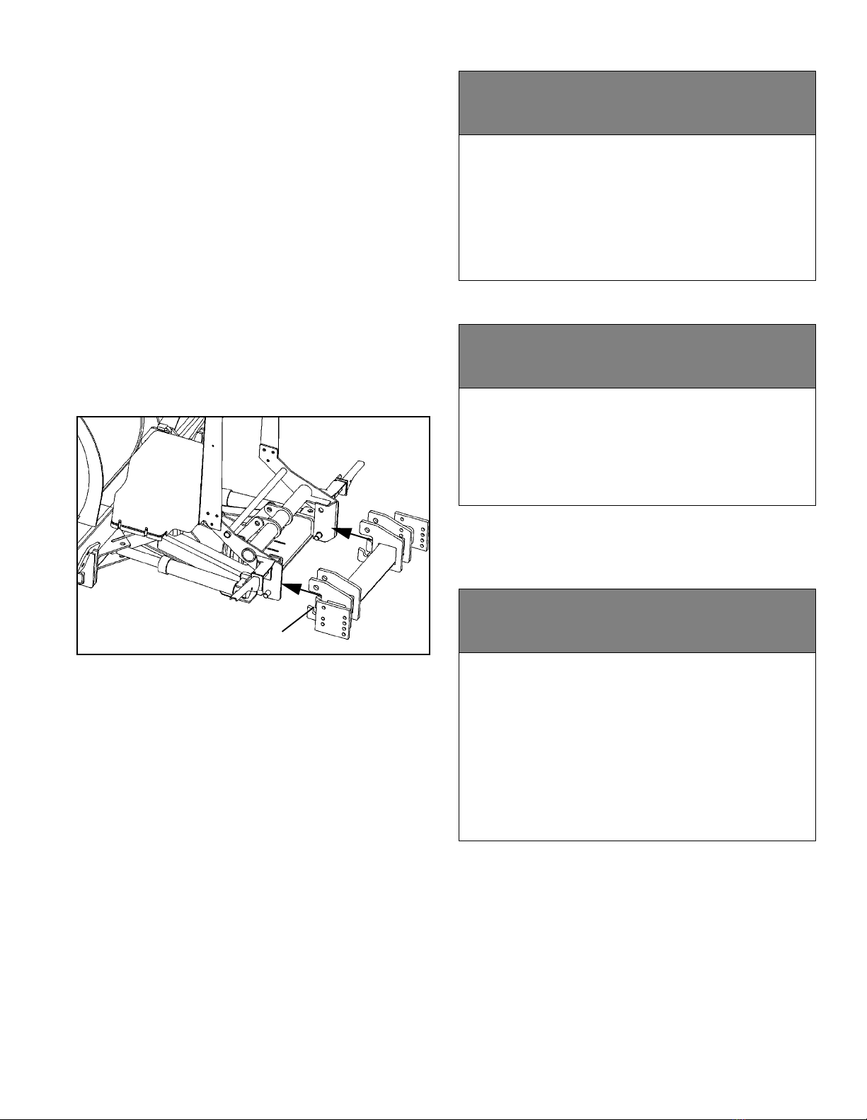
1. Drive truck into plow. Align light/lift bar frame inside of
sub-frame lugs. Pins should fit inside slots cut into sub-
frame lugs. (See Figure 1-1).
Figure 1-1
NOTE: If pins are too high or low to fit into slots on sub-
frame, adjust the height by plugging in the plow and hand
held controller. For Down Pressure Plows - To lower the
pins, turn on down pressure and press down. To raise the
pins, press up. For Gravity Plows - To lower the pins,
place plow in float and push up on light bar. To raise the
pins, press up.
2. Plug in power harness and remove controller from
truck cab. Plug controller into plow.
3. Rotate light/lift bar into position by turning on down
pressure and pressing the lower button. (See Figure 1-2).
SUBFRAME MOUNTED ON TRUCK
cWARNING
When using the hand held controller to raise or
lower the plow A-frame for mounting the plow
to the vehicle, be especially careful of the
movement of the light bar. This movement will
occur when raising or lowering the A-frame or
jack stand.
FAILURE TO FOLLOW CAN RESULT IN INJURY
OR DEATH
cWARNING
Pressing the blade angle functions will result in
the A-frame swinging if it is not secured to the
truck. Do not press the angle function during
plow installation.
FAILURE TO FOLLOW CAN RESULT IN INJURY
OR DEATH
cWARNING
The power cable in front of the truck is wired
directly to the battery. The power cable is
always energized, even if the truck is turned off.
Always replace the protective cap after
disconnecting the plow power cable. Allowing
an unprotected plug to contact metal parts of
the truck may cause electrical component
damage. Never use a metal object to clean the
plug contacts.
FAILURE TO FOLLOW CAN RESULT IN INJURY
OR DEATH

9
Figure 1-2
NOTE: If your plow is not equipped with down pressure
hydraulics you will have to manually rotate the light lift bar
into position by placing plow in float mode and pushing
on the light bar.
4. Put plow into float position by turning down pressure
off. Rotate pin handles down to lock pins in place. (See
Figure 1-3).
NOTE: Upper hitch pins are fully engaged when pin han-
dle is tight against pin bracket and you cannot see the
upper hitch pin between the pin bracket and pin handle.
If upper hitch pins are not fully engaged:
A. Raise plow an inch off the ground, then lower. Or,
B. Turn Down Pressure ON and then OFF.
Upper hitch pins will snap into place.
Figure 1-3
5. Unplug plow from control.
6. Disengage both jack stand pins by pulling on
handles. Raise the jack stand and engage the bottom pin
by pushing on the handle. Make sure pin is engaged in
hole by rotating jack stand back and forth. (See Figure 1-
4).
Figure 1-4
7. Unplug light harness connectors on truck, and
disconnect plow light connectors, which had been
plugged together for corrosion protection during storage
(See Figure 1-5).
cWARNING
Make sure that upper hitch pins are engaged
before moving truck. Hitch pins not fully
engaged could result in the plow separating
from the truck.
FAILURE TO FOLLOW CAN RESULT IN INJURY
OR DEATH
PIN WILL DROP
INTO SLOT
PIN HANDLE
DOWN
PIN HANDLE
DOWN
UPPER
HITCH PIN
JACK STAND
BELL CRANK
LIFT LINK
UPPER PIN
HANDLE
LOWER PIN
HANDLE

10
Figure 1-5
8. Plug plow light connectors into mating connectors on
truck light harness (See Figure 1-6).
Figure 1-6
9. Plug control harness on plow into truck. Plug plow
control inside truck cab.
10. Raise, lower and angle plow to make sure no hoses
or wires pinch in the plow mechanism.
Installing The Cylinder Lock Clamp
1. Raise the plow to the full UP position.
2. Turn the ignition OFF and apply the parking brake.
3. Turn OFF the hand-held controller.
4. Remove the pin from the cylinder lock clamp.
5. Position the cylinder lock clamp around the exposed
(chrome) portion of the lift cylinder with the open side of
the cylinder lock up. Install the pin. (See Figure 1-7).
Figure 1-7
6. Lower the plow so that cylinder lock clamp is tight
against cylinder.
cWARNING
Failure to properly connect plow lights to
vehicle light harness will prevent plow lights
from functioning. Follow proper procedure to
connect light harnesses and test lights before
operating.
FAILURE TO FOLLOW CAN RESULT IN INJURY
OR DEATH
PLOW LIGHT
CONNECTORS
TRUCK LIGHT HARNESS
CONNECTORS
PLOW CONTROL HARNESS
PLOW LIGHTS
CONNECTED TO TRUCK
LIGHT HARNESS
cWARNING
Always install the cylinder lock clamp when the
plow blade is raised and the operator is not
engaged in plowing operations. Equipment
failure or inadvertent operation of the plow
control while driving could allow the plow blade
to fall, resulting in injury.
FAILURE TO FOLLOW CAN RESULT IN INJURY
OR DEATH
cWARNING
Failure to lower plow onto clamp could block
headlights resulting in an accident.
FAILURE TO FOLLOW CAN RESULT IN INJURY
OR DEATH
WIRE LOCK PIN
LIFT
LINK
A-FRAME BOTTOM
BELL
CRANK
CYLINDER
LOCK
CLAMP
CYLINDER
ROD
11
Removing Snow Plow From Vehicle
Choose a location for the plow storage, which will allow
the plow to be removed from the vehicle and not be
moved after removal. Also, choose a location that will not
allow the plow stand to sink into the ground. A dry,
protected area is recommended.
1. Lower plow to the ground, put vehicle in park, turn off
the engine and set the parking brake.
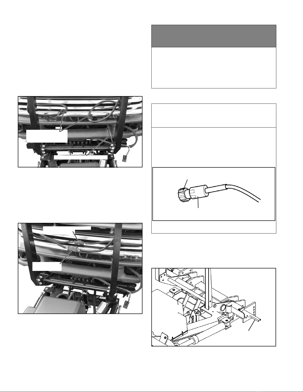
2. Disconnect the plow lights from the truck light
harness (See Figure 1-8). Disconnect the plow control
harness and replace the protective cap.
Figure 1-8
3. To prevent corrosion on the contacts, plug the male
and female connectors on the plow together (See Figure
1-9).
4. To make the truck lights operable, plug the male and
female connectors on the truck light harness together
(See Figure 1-9).
Figure 1-9
5. Turn Down Pressure ON and then OFF.
6. Rotate pin handles up (straight out) to unlock main
pins. (See Figure 1-11).
Figure 1-11
PLOW CONTROL HARNESS
PLOW LIGHTS FROM
DISCONNECT
LIGHT HARNESS
PLOW LIGHT
CONNECTORS
TRUCK LIGHT HARNESS
CONNECTORS
cWARNING
Failure to reconnect the main light harness on
the truck when removing plow will cause truck
lights to not operate, which could cause an
accident. Test lights before operating.
FAILURE TO FOLLOW CAN RESULT IN INJURY
OR DEATH
cCAUTION
When disconnecting the plow control harness,
turn only the locking nut at the end of the
connector. Do not turn the threaded boot.
Turning the threaded boot will break the wires
in the harness and cause the controller to stop
functioning. (See Figure 1-10).
Figure 1-10
LOCKING NUT
(TURN)
THREADED BOOT
(DO NOT TURN)
PIN HANDLE UP
(STRAIGHT OUT)
12
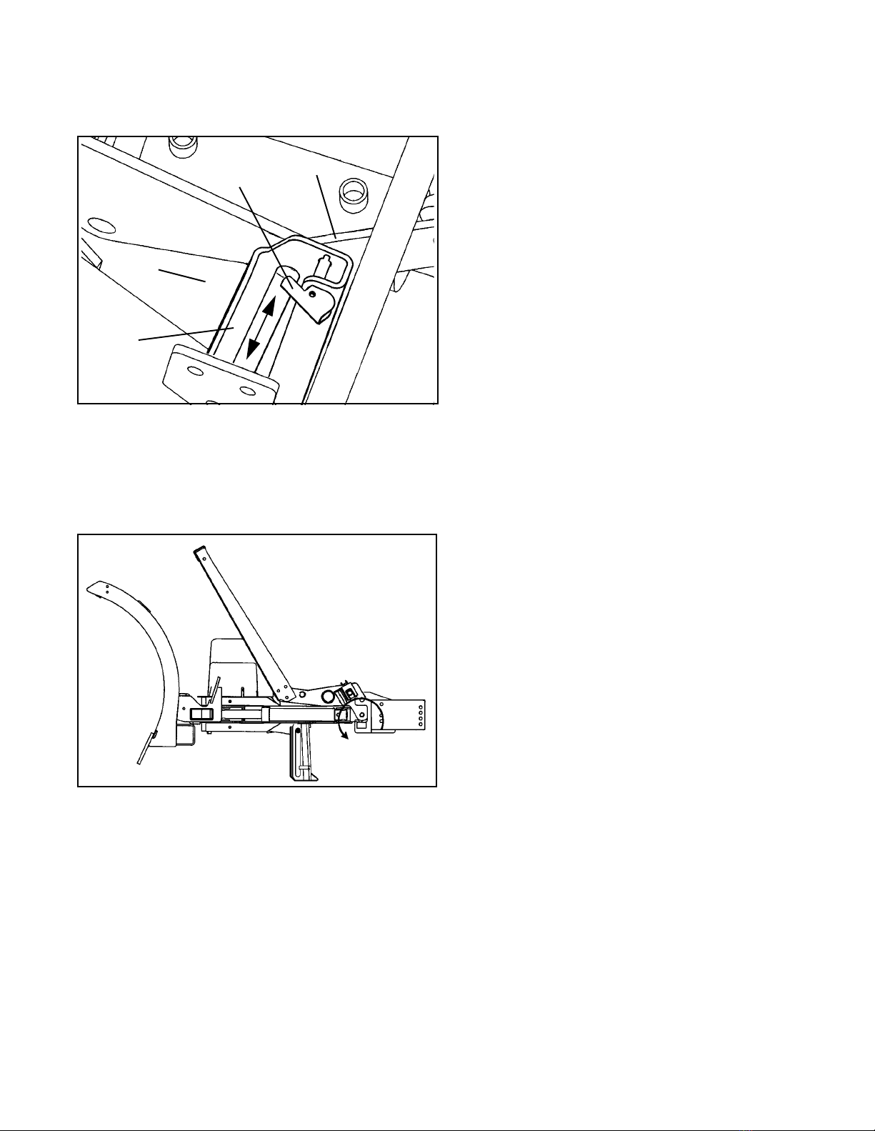
7. Disengage lower jack stand pin by pulling on handle.
Lower the jack stand and engage the top pin by pushing
on the handle. Make sure pin is engaged in hole by
rotating jack stand back and forth.
Figure 1-12
8. Remove controller from truck cab and plug into plow
control harness.
9. Rotate jack stand down and raise A-frame by
pressing the up button. (See Figure 1-13).
Figure 1-13
10. Disconnect power harness, replace protective caps
and back truck away from plow.
Plow Storage
1. If the plow will not be stored on a firm surface (i.e.
concrete or asphalt), place a board or piece of plywood,
etc. under the jackstand to prevent the jackstand foot
from sinking into the ground.
2. To avoid corrosion during storage, coat the exposed
(chrome) portion of the lift and angle cylinders with a light
grease.
3. Grease all pivot points.
4. Top off hydraulic reservoir to minimize trapped air.
5. Make sure that protective caps are on all electrical
connections. Apply a small amount of dielectric grease to
ensure a moisture proof seal on the caps.
6. Check and replace any worn and/or damaged
component, such as cutting edges or deflectors.
Performing preventative maintenance tasks in the spring
when plow is stored will ensure that you will be ready to
plow in the fall.
BELL
CRANK
JACK
STAND
LIFT LINK
UPPER PIN
HANDLE

13
Introduction
Whenever service is necessary, your local dealer knows
your plow best and is interested in your complete
satisfaction. Return your snow plow to your local dealer
for maintenance service or any other assistance you may
require. If you are unable to do so, this Trouble Shooting
Guide should help you determine the problem. Also, there
are Repair Manuals available from your local dealer.
However, before attempting the servicing of your plow,
you should possess good mechanical abilities and a total
understanding of the mechanism.
PLEASE: Before calling parts and service personnel be
certain that:
1. You have read this guide carefully and are certain
that all of the suggestions pertaining to your problem
have been attempted.
2. You have the following information available.
A. Date Snow Plow was originally installed.
B. Power Pack Model Number.
C. Power Pack Serial Number.
D. Controller Serial Number.
E. Blade Model Number.
F. Blade Serial Number.
G. Pump Serial Number.
This information should be recorded on page 2 of this
Owners Manual.
Troubleshooting-Quick
Reference General
1. Check to see that controller is “on”.
2. Check all wiring to be sure that battery terminals are
clean and connections to battery, circuit breaker,
solenoid, switches and all connectors on plow harness
are clean and tight.
3. Check oil level in hydraulic system reservoir.
4. Check for external leakage at cylinders, hoses and
power unit.
5. Check the voltage at the coils which operate the
solenoid valves to be sure that the voltage at the coils is a
minimum of 9-1/2 volts DC.
cCAUTION
First read all warning instruction, the safety
messages, and directions before attempting
any adjustments or repairs to your unit!
TROUBLESHOOTING

14
TROUBLESHOOTING CHART
PROBLEM PROBABLE CAUSE CORRECTIVE ACTION
Plow will not lift (Motor runs) Hydraulic fluid level low See Maintenance Section
Defective Control Unit Refer to Dealer
Improper main pressure relief valve
pressure setting, debris causing
valve to stick
Refer to Dealer
Breather cap plugged See Maintenance Section
Faulty raise or raise/float solenoid
coil
Refer to Dealer
Raise/lower solenoid valve stuck in
lower position
Refer to Dealer
Raise/lower cylinder frozen or
binding
Refer to Dealer
Defective or sticking Down Pressure
Solenoid Valve
Refer to Dealer
Pick-up tube filter plugged See Maintenance Section
Pick-up tube is not submerged in
fluid
See Maintenance Section
Machine failure Refer to Dealer
Weak battery and/or charging
system
Refer to Dealer
Motor continues to run and will
not shut-off
Motor Solenoid defective Refer to Dealer
Electrical short Refer to Dealer
Plow lifts slowly Hydraulic fluid level low See Maintenance Section
Breather cap plugged See Maintenance Section
Improper main relief pressure
setting, debris causing valve to stick
Refer to Dealer
Pick-up tube filter plugged See Maintenance Section
Improper oil viscosity for outside air
temperature, unit not at normal
operating temperature
See Maintenance Section
Defective Lift Cylinder Refer to Dealer
Machine failure Refer to Dealer

15
Fluid leaking at Pump Assembly Hydraulic fittings not torqued
properly (too tight, too loose)
Refer to Dealer
O-Rings between valve block and
endhead are cut or not seating
properly
Refer to Dealer
O-Rings between endhead and
reservoir cut or not seating properly
Refer to Dealer
Reservoir over-full See Maintenance Section
O-Ring on solenoids or pressure
switches defective
Refer to Dealer
Endhead cracked Refer to Dealer
Valve body cracked Refer to Dealer
Unit lifts but does not hold - first
action
Dirt in check valve or Float/DP
solenoid valve
Cycle raise and lower system to flush
debris
Float/DP solenoid valve sticking Cycle raise and lower system to un-
stick valve
Unit lifts but does not hold -
second action
Dirt or debris in check valve Refer to Dealer
Check valve spring broken Refer to Dealer
Float/DP solenoid valve sticking Refer to Dealer
Seals O-Ring(s) on Float/DP
solenoid valve damaged
Refer to Dealer
Raise/lower ram defective Refer to Dealer
Machine failure Refer to Dealer
Unit will not lower
NOTE: Only in non- down pres-
sure mode
Plugged breather cap See Maintenance Section
Low or no current available at Float/
DP Solenoid
Refer to Dealer
Float/DP solenoid valve sticking Refer to Dealer
Float/DP solenoid coil defective Refer to Dealer
Raise lower ram defective allowing
movement in one direction only
Refer to Dealer
Machine failure Refer to Dealer
PROBLEM PROBABLE CAUSE CORRECTIVE ACTION

16
Unit will not lower
NOTE: In down pressure mode
only
See all above conditions Refer to Dealer
Raise lower ram defective allowing
movement in one direction only
Refer to Dealer
Defective Control Unit Refer to Dealer
Defective down pressure solenoid Refer to Dealer
Machine failure Refer to Dealer
Motor will not run Motor brushes worn/commutator
worn or dirty
Refer to Dealer
Seal between motor and pump
defective allowing oil to enter motor
housing
Refer to Dealer
Defective Start Solenoid Refer to Dealer
Motor seized Refer to Dealer
Machine failure Refer to Dealer
Blade wing moves in one
direction only
Solenoid valve sticking or defective Refer to Dealer
Crossover relief valve defective or
sticking
Refer to Dealer
Low or no current available at extend
or retract solenoid valve
Refer to Dealer
Angle cylinder defective allowing
movement in one direction only
Refer to Dealer
Machine failure Refer to Dealer
Blade wing will not move Hydraulic fluid level low See Maintenance Section
Crossover pressure relief valve
setting too low
Refer to Dealer
Solenoid valve sticking or defective Refer to Dealer
Low or no current available at
solenoid valve
Refer to Dealer
Wing cylinder binding or frozen Refer to Dealer
Pick up tube not submerged in fluid See Maintenance Section
Machine failure Refer to Dealer
Blade wing will not move, but
plow raises when trying to move
wings
Raise solenoid valve defective or
sticking
Refer to Dealer
PROBLEM PROBABLE CAUSE CORRECTIVE ACTION

17
Blade wing moves very slowly Hydraulic fluid level low See Maintenance Section
Crossover Relief Valve defective or
sticking
Refer to Dealer
Improper oil viscosity for outside air
temperature, unit not at normal
operating temperature
See Maintenance Section
Defective Wing Cylinder Refer to Dealer
Dirt or debris in Solenoid Valve Refer to Dealer
Blade wings will not hold position
(fold rearward)
Defective or dirt/debris in Wing
Relief Valve
Refer to Dealer
Defective or sticking Solenoid Valve Refer to Dealer
Dirt or debris in Solenoid Valve Refer to Dealer
Defective Wing Cylinder Refer to Dealer
PROBLEM PROBABLE CAUSE CORRECTIVE ACTION

18
General
• Before operating, perform a thorough visual
inspection of the equipment. Look for fluid leaks,
cracked, bent or broken components, loose nuts,
bolts or attachments and proper fluid levels.
• A clean hydraulic system is essential to long pump
life and proper performance.
• When adding oil to the reservoir, wipe the area
around the filler port clean before removing the
breather cap. Use clean oil and a clean funnel, (DO
NOT use a cloth or rag to strain the oil).
IMPORTANT: Hydraulic unit comes from factory
charged with Type 5606. If additional oil is added it
must be compatible with Type 5606. If another type of
oil has been used in the system the same type of oil
must be used for topping off system. Improper
hydraulic fluid can cause operating problems in cold
weather.
• The operational environment for snow plows is an
extremely harsh and corrosive one.
• Ensure all electrical connections are clean and
tight.
• To prevent rust from forming, clean and repaint
exposed metal surfaces.
• NEVER operate the equipment with the protective
covers or guards removed.
Periodic Inspection
After approximately every 20 hours of operation perform
the following inspections procedures:
1. Inspect the plow assembly including the sub-frame
assembly for any damage or excessive wear. Also
inspect all fasteners to insure that they are properly
tightened. If any fasteners are loose re-tighten to the
proper torque (Refer to the Torque Specification Chart in
this manual). Also carefully inspect adjacent area for
damage or wear as well as carefully inspecting all
adjacent fasteners for proper torque.
2. Apply a small amount of light oil to the hitch pins and
pivots, to pivot pins between the center blade assembly
and the intermediate pivot assembly, between lift and
swing cylinder pivot pins and the lift linkage pivots.
3. Lubricate the wing pivot shafts with a good quality HP
Lithium based grease.
NOTE: For extremely cold weather plowing, continuous
sub zero operation, an alternative is to remove the
grease fittings and fill the grease cavity with SAE 140
gear oil, and then replace the grease fitting.
Special Fasteners Torques and Require-
ments
IMPORTANT: Incorrectly securing fasteners may
result in incorrect operation, excessive wear, and
early failure of plow components. It may also void
your warranty.
• ALWAYS check to make sure you are using the
correct torque specification for the fastener you are
using.
• DO NOT use any lubricants on the threads of any
fastener unless specifically called for in the
assembly or maintenance story for that component.
• NEVER use liquid locking materials, such as
Locktite™ or Threadmaker™, on any fasteners
unless specifically called for in an assembly or
maintenance story for that component.
Standard Fasteners:
The Torque Specifications Chart on page 26 of this
manual should be used as the guide for fastener torque
requirements for most standard fasteners used on the
plow.
Standard fasteners with special torque requirements will
be noted in assembly or service stories pertaining to the
specific piece of equipment.
Hydraulic Fittings:
Hydraulic fittings with lock nuts should be assembled with
at least three full turns of the fitting in the port and then the
lock nut should be tightened to 27 lb-ft.
Wing Cylinder Attaching Fasteners:
Base end and rod end attachment cap screws are always
assembled with the cap screw head UP.
Always use a nylock nut and only torque the nut to 25 to
30 lb-ft. DO NOT overtighten these fasteners.
Overtightening of wing cylinder attachment fasteners may
bind cylinder and cause excessive cylinder wear and/or
restrict wing movement.
Bellcrank Assembly to Lift Arm Assembly Fasteners:
Apply Locktite 242™ (Blue) to the threads of the cap
cWARNING
Before servicing plow, lower plow to the ground
or onto cylinder lock clamp and disconnect
main power harness.
FAILURE TO FOLLOW CAN RESULT IN INJURY
OR DEATH
MAINTENANCE

19
screws and tighten the jam nut to 70 lb-ft. Then place the
lock nut on the cap screw and tighten to 70 lb-ft.
Pivot Frame Assembly:
Install the 1" slotted nut on the threaded end of the special
screw and tighten finger tight. Then tighten the nut
another 2/3 to 1 full turn and line up a slot in the nut with
the cross hole in the special screw. Install the 3/16"x2"
cotter pin in the special screw and spread the ends of the
cotter pin.
Hydraulic Cylinders
To avoid corrosion during storage, coat the exposed
(chrome) portion of the lift and angle cylinders with a light
grease.
Electrical Quick Disconnect Plugs
Install protective caps or plug together quick disconnect
ends to prevent corrosion from forming on terminal ends
during storage or when plow is disconnected from vehicle.
Service Intervals
It is recommended to change the fluid in the hydraulic
system once a season.
Fluid Requirements
IMPORTANT: Hydraulic unit comes from factory
filled with Type 5606. If additional oil is added it must
be compatible with Type 5606.
NOTE: when Type 5606 is not available Exxon UNIVIS
J13 or equivalent may be used.
Changing Oil and Cleaning Filter Screen
NOTE: We recommend cleaning the filter screen at every
oil change, this will help ensure maximum life and maxi-
mum performance from the pump assembly.
1. Lower plow assembly to ground, put vehicle in park
and turn off engine. Turn hand-held controller off.
2. Remove two (2) self-tapping screws from the front of
the cover and loosen two (2) cap screws from the rear.
Remove the cover.
3. Remove the filler/breather cap from the reservoir.
(See Figure 2-14).
cCAUTION
• Using the proper oil increases the life
expectancy of the most critical part of your
plow; the Hydraulic power unit.
• Failure to use the proper oil can cause
extensive damage to the power unit, seals and
hydraulic rams.
• Improper oil can cause operating problems and
poor performance in cold weather.
cCAUTION
Using the proper oil increases the life
expectancy of the most critical part of your
unit; the Hydraulic power unit.
cWARNING
• Allow the system to cool down before draining
oil or handling system components. Serious
burns can result from contact with hot oil.
• Never disconnect any hydraulic line or fitting
with the unit in the raised position. Always
lower the unit and relieve pressure before
removing any lines or caps.
FAILURE TO HEED CAN RESULT IN INJURY
OR DEATH.
cWARNING
Ensure engine is OFF and set parking brake
before working on plow. Vehicle movement,
equipment failure or inadvertent operation of
the control switches during maintenance could
result in serious injury
FAILURE TO HEED CAN RESULT IN INJURY
OR DEATH.
This manual suits for next models
2
Table of contents
Other Sno-Way Automobile Accessories manuals


