SNR SNR-VP-6020 User manual

SNR-VP-6020
User Manual

Safety Notices
Please read the following safety notices before installing or using this phone. They are crucial for the safe
and reliable operation of the device.
Please use the external power supply that is included in the package. Other power supplies may cause
damage to the phone, affect the behavior or induce noise.
Before using the external power supply in the package, please check with home power voltage.
Inaccurate power voltage may cause fire and damage.
Please do not damage the power cord. If power cord or plug is impaired, do not use it, it may cause fire
or electric shock.
The plug-socket combination must be accessible at all times because it serves as the main disconnecting
device.
Do not drop, knock or shake it. Rough handling can break internal circuit boards.
Do not install the device in places where there is direct sunlight. Also do not put the device on carpets
or cushions. It may cause fire or breakdown.
Avoid exposure the phone to high temperature, below 0℃or high humidity. Avoid wetting the unit
with any liquid.
Do not attempt to open it. Non-expert handling of the device could damage it. Consult your authorized
dealer for help, or else it may cause fire, electric shock and breakdown.
Do not use harsh chemicals, cleaning solvents, or strong detergents to clean it. Wipe it with a soft cloth
that has been slightly dampened in a mild soap and water solution.
When lightning, do not touch power plug or phone line, it may cause an electric shock.
Do not install this phone in an ill-ventilated place.
You are in a situation that could cause bodily injury. Before you work on any equipment, be aware of
the hazards involved with electrical circuitry and be familiar with standard practices for preventing
accidents.
2

Table of Content
1.Introducing FV6020 VoIP Phone…………………………………………………………..5
1.1. Thank you for your purchasing FV6020 ................................................................................. 5
1.2. Delivery Content
........................................................................................................................ 5
1.3. Keypad
........................................................................................................................................ 6
1.4. Port for connecting
.................................................................................................................... 7
2.Initial connecting and Setting………………………………………………………………8
2.1. connect the phone…………………………………………………………………8
2.2. Initial Setting
............................................................................................................................. 9
2.2.1. PPPoE mode
. ...................................................................................................................... 9
2.2.2. Static IP mode
.................................................................................................................... 9
2.2.3. DHCP mode……………………………………………………………………
10
3. Basic Functions………………………………………………………………………. ….11
3.1. Basic operation……………………………………………………………………. ………..11
3.1.1. Accepting a call
……………………………………………………………………. …..11
3.1.2. Making a call
..........................................................................................................................11
3.1.3. Ending a call
..........................................................................................................................11
3.1.4. Transferring a call
.................................................................................................................11
3.1.5. Calling Hold and 3 ways call
............................................................................................... 12
3.1.6. Calls list
................................................................................................................................. 12
3.2. The high-level operation……………………………………………………………………...12
4. Setting……………...……………………………………………………………. ………..13
4.1. Setting methods
....................................................................................................................... 13
4.2. Setting via Web Browse………………………………………………………………............14
4.2.1. Current Status
...................................................................................................................... 14
4.2.2. Network
................................................................................................................................. 15
4.2.2.1. WAN Config
............................................................................................................. 15
4.2.2.2. LAN Config
.............................................................................................................. 16
4.2.3. VoIP
....................................................................................................................................... 17
4.2.3.1. SIP Config
................................................................................................................ 17
4.2.3.2. IAX2 Config
............................................................................................................. 19
4.2.4. Advance
................................................................................................................................. 20
4.2.4.1. DHCP Service
.......................................................................................................... 20
4.2.4.2. NAT Configuration
................................................................................................. 21
4.2.4.3. Net Service
................................................................................................................ 23
4.2.4.4. Firewall Config
........................................................................................................ 24
4.2.4.5. QoS Config
............................................................................................................... 25
4.2.4.6. Advance SIP Configuration.................................................................................... 27
4.2.4.7. Digital Map Configuration ..................................................................................... 29
4.2.4.8. Call Service
.............................................................................................................. 30
4.2.4.9. MMI Filter
............................................................................................................... 32
4.2.4.10. DSP Config
............................................................................................................. 32
4.2.4.11. VPN Config
............................................................................................................ 33
4.2.5. Dial-Peer Setting
................................................................................................................... 34
4.2.6. Config Manage
...................................................................................................................... 36
4.2.6.1. Save Config
.............................................................................................................. 36
4.2.6.2. Clear Config
............................................................................................................. 37
4.2.6.3. Backup Config
......................................................................................................... 37
4.2.7. Update
................................................................................................................................... 37
4.2.7.1. Web Update
.............................................................................................................. 37
4.2.7.2. FTP/TFTP Update
................................................................................................... 38
4.2.7.3. Auto Provisioning
.................................................................................................... 38
4.2.8. System Manage
..................................................................................................................... 39
4.2.8.1. Account Config
........................................................................................................ 39
4.2.8.2. Syslog Config
............................................................................................................ 40
3

4.2.8.3. Phone Book
.............................................................................................................. 41
4.2.8.4. Time Config
.............................................................................................................. 41
4.2.8.5. Logout &Reboot
...................................................................................................... 42
4.3. Settings via phone’s keyboard.
............................................................................................... 42
4.3.1. How to set via the phone’s keyboard. ....................................................................... 42
4.3.2. Phone menu
................................................................................................................. 43
5. Appendix…………………….…………………………………………………. ………...43
5.1. Specification
............................................................................................................................. 43
5.1.1. Device specification
.................................................................................................... 43
5.1.2. Voice Features
............................................................................................................. 43
5.1.3. Network Features
....................................................................................................... 44
5.1.4. Maintenance and Management ................................................................................. 44
5.2. Key mapping
............................................................................................................................ 44
4

1. Introducing FV6020 VoIP Phone
1.1. Thank you for your purchasing FV6020
Thank you for your purchasing FV6020, FV6020 is a full-feature telephone that provides voice
communication over the same data network that your computer uses. This phone functions not only
much
like a traditional phone, allowing to place and receive calls, and enjoy other features that traditional
phone
has, but also it own many data services features which you could not expect from a traditional
telephone.
This guide will help you easily use the various features and services available on your phone.
1.2. Delivery Content
Please check whether the delivery contains the following parts:
The base unit with display and keypad
The handset
The handset cable
The power supply
The Ethernet cable
5

1.3. Keypad
The numeric keypad with the keys 0 to 9, *, and # is used to enter
Digits and letters, additionally, the following keys are available:
Key mapping:
Key
Description
In idle state,press the MENU key to
call up the menu
.
The phone can realize the following features by the UP key or the DOWN key.
When you pick up the handset or during calling, use the UP key or the DOWN key
to
adjust volume; Use the UP key or the DOWN key to browse menu; cancel or
confirm
action; browse calling list.
In idle state, press the SYSINFO key for once to look up this VoIP Phone Number,
this VoIP Phone local IP address for twice and Local Gateway IP address for three
times.
Press the ENTER key to confirm action, selection, or enter into the next menu in
menu mode.
Use the EXIT key to return to the previous menu in menu mode.
In idle state, press the IN key or the OUT key to browse missed call, received call
or
dialed call, and realize dialing by the REDIAL/ SEND key.
In idle state, press the REC key to look up new, old received Voice record and
user-defined voice record, and plays them. During call, press the REC key to record
call content.
In idle state, press the PBOOK key to access phone book, then use the REDIAL/
SEND key to dial. You can browse phone book by the UP key or the DOWN key.
In menu mode, use the DEL key to delete.
Mute microphone on/off, during a call.
Press the HOLD key, input the third party telephone number, then press the # key to
realize the third party call. If you want to switch back from the third party call,
press
the HOLD key again.
6

Press the TRANSFER key during call, can realize blind transfer and attended transfer.
Press the REDIAL/SEND key to dial the last dialed number.
Select contact name or telephone number in Phone book, Then press this key to send
the number.
Switch to hand-free mode and back.
1.4. Port for connecting
POWER
DC 5V
Power switch
Power port
Select ON/OFF
Output: 5V/1A
LAN Network port Connect it to PC
WAN Network port Connect it to Network
The phone has two Network ports: The WAN port and the LAN port. Before you connect the power source,
please carefully read Safety Notices of this user manual.
7
2. Initial connecting and Setting
2.1. connect the phone
Step 1: Connect the IP Phone to the corporate IP telephony network. Before you connect the phone to the
network, please check if your network can work normally.
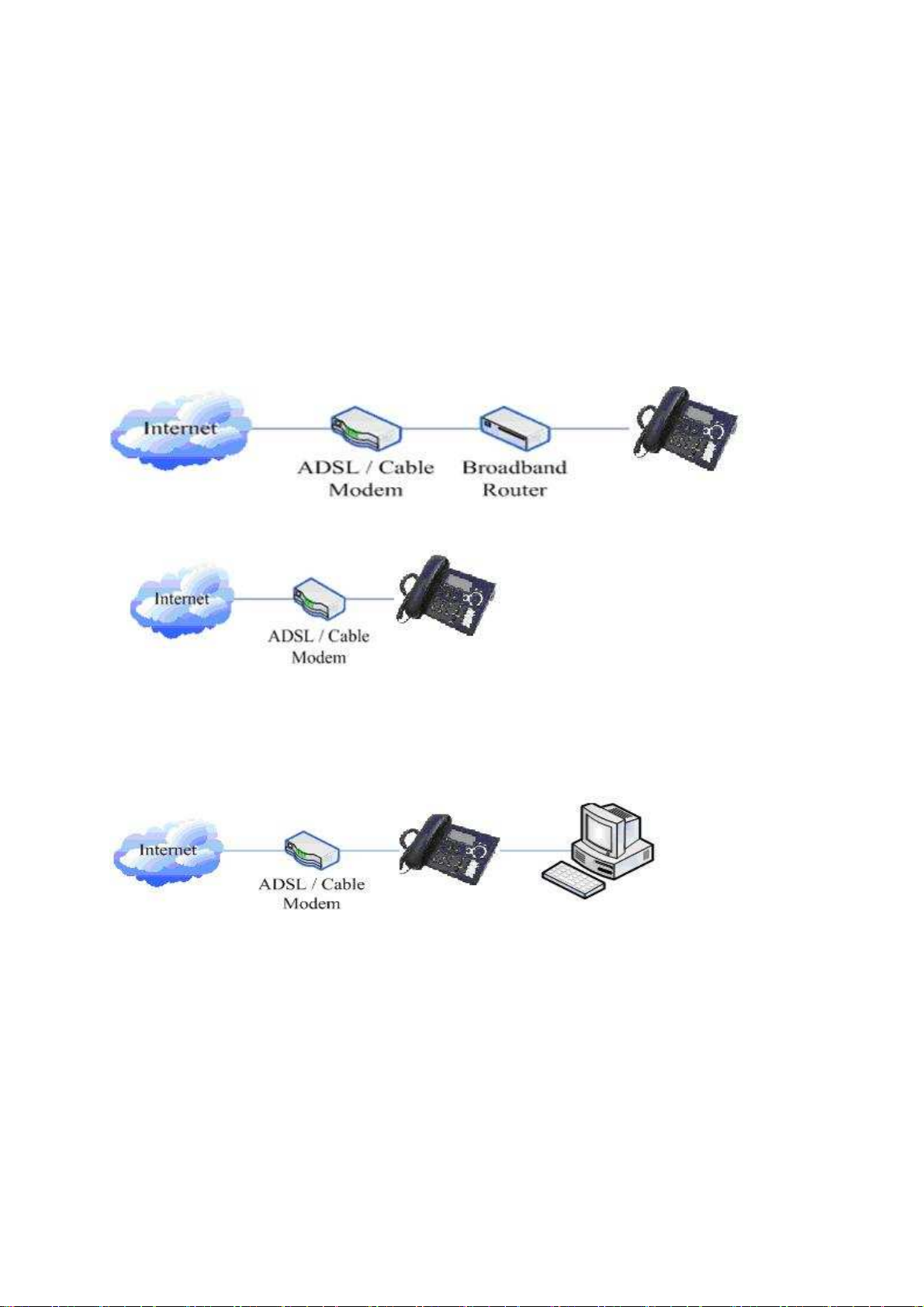
You can do this in one of two ways, depending on how your workspace is set up.
Direct network connection—by this method, you need at least one available Ethernet port in your workspace.
Use the Ethernet cable in the package to connect WAN port on the back of your phone to the Ethernet port in
your workspace. Since this VoIP Phone has router functionality, whether you have a broadband router or not,
you can make direct network connect. The following two figures are for your reference.
Shared network connection—Use this method if you have a single Ethernet port in your workspace with
your desktop computer already connected to it. First, disconnect the Ethernet cable from the computer and
attach it to the WAN port on the back of your phone. Next, use the Ethernet cable in the package to connect
LAN port on the back of your phone to your desktop computer. Your IP Phone now shares a network
connection with your computer. The following figure is for your reference
.
Step 2: Connect the handset to the handset port by the handset cable in the package.
Step 3: connect the power supply plug to the DC 5V adapter port on the back of the phone. Use the power
cable to connect the power supply to a standard power outlet in your workspace.
Step 4: push the on/off switch on the back of the phone to the on side, then the phone’s LCD screen displays
“WAIT LOGON”. Later, a ready screen typically displays the date, time and current network mode.
If your LCD screen displays different information from the above, you need refer to the next section “Initial
setting” to set your network online mode.
If your VoIP phone registers into corporate IP telephony Server, your phone is ready to use.
8

2.2. Initial Setting
This VoIP Phone provides you with rich function and parameters setting. If you have enough knowledge
about network and SIP protocol, it is better for you to understand many parameters. But if you know little
about network and SIP protocol, you can also easily make initial setting according to the following steps to
enjoy rapidly high quality voice and low cost from this VoIP Phone.
Before make initial setting, please check if your corporate IP telephony network can work normally, and you
have finished “connect the phone”.
This VoIP Phone Supports DHCP by default. It will receive an IP address and other network-related settings
(Netmask, IP gateway, DNS server) from the DHCP server. If your network supports DHCP, you can
connect this VoIP Phone directly to the network. If your network doesn’t support DHCP, you need change
this VoIP Phone’s network connection setting. According to the following steps, change this VoIP Phone’s
DHCP network connection setting into PPPoE or static IP which your network supports at present.
2.2.1. PPPoE mode.
1. Prepare your PPPoE account name and password.
2. Press the MENU key, the LCD screen will display “INPUT PASSWORD”.
3. Input the password (default value is 123), and press the ENTER key, the LCD screen will display
“NETWORK”.
4. Press the ENTER key and LCD screen will display “LAN”, press the DOWN key, enter it by the ENTER
key, the LCD screen will display “STATIC NET”. Then press the DOWN key again, enter it by the
ENTER key, the LCD screen will display “USER NAME”.
5. Press the DOWN key, the LCD screen will display “PASSWORD”. Then press the ENTER key, and the
DEL key, input your PPPoE’s password and confirm it by the ENTER Key, the LCD screen will display
the password which you inputted.
6. Press the EXIT key to return to the previous menu, then press the DOWN key, the LCD screen will
display “USER NAME”. Press the ENTER key, and the DEL key, input your PPPoE’s account name,
then press the ENTER key to confirm it, the LCD screen will display the PPPoE’s account name which
you inputted.
7. Press the EXIT key for four times and press the DOWN key, till the LCD screen display “SYSTEM”.
8. Press the ENTER key, the screen display “SAVE”, then press the ENTER key again, the LCD screen will
display “ARE YOU SURE”.
9. Press the ENTER key, the phone will save your setting and the LCD screen will display “SAVING”, then
return to display “SAVE”.
10. Press the EXIT key twice, then press numeric key “3”and hold until the screen display “ARE YOU
SURE”. Press the ENTER key, the screen will display “CHANGING”, which means that the phone is
trying to switch to PPPoE mode. If the icom “PPPoE” on the top of the screen keeps blink, it shows that
the phone is trying to access the PPPoE server., and the IP is still static IP if you press SYSINFO key to
display the current IP; if the icon “PPPoE” is showed without blink, it means that the phone has already
gotten IP from PPPoE server.
2.2.2. Static IP mode:
1. Prepare your phone’s network parameters. They are IP Address of this phone, Subnet Mask, Default
Gateway/ Router and DNS. You can ask your VoIP service provider for those parameters.
2. Press the MENU key, the LCD screen will display “INPUT PASSWORD”.
3. Input password (default is 123), then press the ENTER key, the LCD screen will display” NETWORK”.
4. Press the ENTER key, and the LCD screen will display “LAN”. Press the DOWN key, then the ENTER
key, the LCD screen will display “STATIC NET”.
5. Press the ENTER key, the LCD screen will display “IP”. Press the ENTER key again and then the DEL
key, input your desired IP address for your IP phone and confirmed by pressing the ENTER key, then the
LCD will display the input IP address. When inputting IP with keypad, use “*” instead of “.”.
6. Press the EXIT key to return to previous menu, then press the DOWN key for twice, the LCD screen will
9

display “DNS”. Press the ENTER key then the DEL key, input your DNS address and confirm it by
pressing the ENTER key, and then the LCD will display the input DNS address.
7. Press the EXIT key to return to the previous menu, and then press the DOWN key, the LCD screen will
display “GATEWAY”. Press the ENTER key again and then the DEL key, input your gateway’s IP
address and confirm it by pressing the ENTER key, the LCD screen will display the input gateway
address.
8. Press the EXIT key to return to the previous menu, and then press the DOWN key, the LCD screen will
display “NETMASK”. Press the ENTER key again and then the DEL key, input your netmask and press
the ENTER key to confirm it. The LCD screen will display the input netmask.
9. Press the EXIT key for four times and press the DOWN key, till the LCD Screen displays “SYSTEM”.
11. Press the ENTER key, the LCD screen will display “save”, then press the ENTER key again, the LCD
screen will display” ARE YOU SURE”.
12. Press the ENTER key, this phone will display “SAVING”, then return to display “SAVE”.
13. Press the EXIT key twice to exit the menu, and then press the numeric key 1 till the LCD screen displays
“ARE YOU SURE”. Press the ENTER key, the LCD screen will display “CHANGING”, If the icon
“static” on the top of screen shows without blink, it means phone has already used the static IP.
2.2.3. DHCP mode
Press the numeric key 2 and hold till the LCD screen displays “ARE YOU SURE”. Press the ENTER key,
the LCD screen will display “CHANGING” and this VoIP phone is trying to switch to DHCP mode. If the
icom “DHCP” on the top of the screen keeps blink, it shows that the phone is trying to access the DHCP
server., and the IP is 0.0.0.0 if you press SYSINFO key to display the current IP; if the icon “DHCP” is
showed without blink, it means that the phone has already gotten IP from DHCP server.
10

3. Basic Functions
3.1. Basic operation
3.1.1. Accepting a call
There are four methods to accept an incoming call:
Pick up handset to accept incoming calls.
Press the SPEAKER button
If you need switch from a hands-free call to handset, please pick up the handset directly.
If you need switch from a handset call to hands-free, please press the SPEAKER button, and then hang
up the handset.
3.1.2. Making a call
Use handset
Pick up the handset, and the LCD screen will display “PLEASE DIAL” and you will hear dialing tone
at the same time, then input the phone number and end by the # button. When you hear long ring “du,
du…” from handset and the LCD screen display “CALLING” the call is through. Hang up the handset
to end the call.
Use hands-free
Press the SPEAKER button and the LCD screen will display “PLEASE DIAL” and you will hear
dialing tone at the same time, then input the phone number and end by the #button. When you hear long
ring “du, du…” and the LCD screen display “CALLING” the call is through. Press the SPEAKER
button again to end the call.
Use the phone book
Press the PBOOK button then the ENTER button you will enter into the phone book. Press the
UP/DOWN button to select your desired contact person, then press the REDIAL/SEND button to dial
the call.
Onhook dial
Input the called number, and press # key or REDIAL/SEND button, phone will dial the call and use
hands-free automatically.
3.1.3. Ending a call
Hangs up by handset onhook
Hangs up by press speaker when in hands-free
Hangs up a call when in call waiting state. If you are in call waiting state, you could press # key to hang
up the current call, and switch to the other call to keep talking.
Pressing # key will not hang up if there is only one call currently.
3.1.4. Transferring a call
Call transfer has several ways to realize:
1. When A talks to B, B may press the HOLD key and dial to C phone number. After B talks to C ( or B
hear alert from C ), B presses the TRANSFER key; B could hang up, and A will get through to C.
2. When A talks to B, there is C call incoming to B; B may press the HOLD key to hold A, and talks to C,
pressing the TRANSFER key, so A will get through to C.
3. When A talks to B, B presses the TRANSFER key, dial C phone number and # key, B could hang up and
A will get through to C.
1 and 2 are attended transfer; 3 is blind transfer.
Notice to VoIP Phone Carrier: Your VoIP phone server need support FRC3515, or else transferring can not
work.
11

3.1.5. Calling Hold and 3 ways call
There are two modes to enjoy hold function:
1. Press the HOLD key during a call, and the call will be on hold. While a call is on hold, you can establish
another call by dialing your desired number and confirm it by the # button. Pressing the HOLD key again
will resume the first call. By using hold function, you can talk with only one party; the other party who is
on hold can’t talk with you. If you press the * button, you will enter into 3 ways call.
2. If the third party calls you during a call, the LCD screen will display the incoming call number. Press the
hold key or # key to hold the first call, and then you can talk with the third party. By using hold function,
you can talk with only one party; the other party who is on hold can’t talk with you. If you press # key,
phone will hang up the first call, and then accept the new incoming call.
Notice: You must enable the calling waiting or else calling hold can’t work.
3.1.6. Calls list
The VoIP phone maintains lists of missed, received, and dialed calls. Each list can contain up to 100
entries. If the call list capacity is full, new call will replace the first call. If you stop power supply or
restart the phone, the record will disappear.
Missed Calls
Press the IN key, and then the UP/DOWN key, till the LCD screen display “MISSED”. Press the
ENTER key, the LCD screen will display the missed call number and sequence numbers of the missed
calls.
You can press the REDIAL/SEND key to dial this phone number, or you can press the ENTER key,
the LCD screen will display the time of the missed calls. If there is no one missed calls, the LCD will
display “LIST IS EMPTY”.
Received Calls
Press the IN key, and then the UP/DOWN key, till the LCD screen display “RECEIVED”. Press
ENTER key, the LCD screen will display the received call numbers and sequence numbers of the
received calls. You can press the REDIAL/SEND key to dial this phone number, or you can Press the
ENTER key, the LCD screen will show the time of the received call. If there is no one received call,
the LCD will display “LIST IS EMPTY”.
Dialed calls
Press the OUT key, the LCD screen will display the phone numbers and sequence numbers of the
dialed calls. You can press the REDIAL/SEND key to dial this phone number, or press the UP/DOWN
key to browse all records of the dialed calls. If there is on one dialed calls, the LCD will display “LIST
IS EMPTY”.
3.2. The high-level operation
This VoIP Phone provides more advanced functions after setting at the permission scope of SIP server.
Please refer to next section to operate.
12

4. Setting
4.1. Setting methods
VoIP Phone is different from the traditional phone; it need be set to make it active. If your VoIP service
provider asks you to set this phone, you can do it easily according to the following methods.
This VoIP Phone can be set via three different setting methods:
The phone key
The web browser on PC
Telnet
This Manual will tell you about the setting methods via the web browser on PC.
4.2. Setting via Web Browse
When this phone and your PC are connected to your network, enter the IP address of the wan port in this
phone as the URL (e.g. http://xxx.xxx.xxx.xxx/ or http://xxx.xxx.xxx.xxx:xxxx/).
If you do not know the IP address, you can look it up on the phone’s display by pressing the key
“SYSINFO” for at most three times.
After you enter the IP address, you will see the following web interface.
This phone provides different two privileges for different users to set it.
The two privileges are guest and administrator respectively. In guest privilege, user can see but not modify
Register/Proxy Sever Address and port of SIP, advance SIP and Iax2. In administrator privilege, user can see
and modify all setting parameters.
Default value in guest privilege
Username: guest
Password: guest
Default value in Administrator privilege
Username: admin
Password: admin
Input username and password, click “logon”, and you will enter setting web interface.
There is a selection menu on the left side of the web interface. Click on the desired submenu; the current
settings of this submenu will be displayed in the larger field on the right. You can now modify and store the
values by using mouse and keyboard of your PC. To save the changes, click on the submenu of “Save
Config” under “Config Manage”, then click the “Save” button on the right field.
13
4.2.1. Current Status
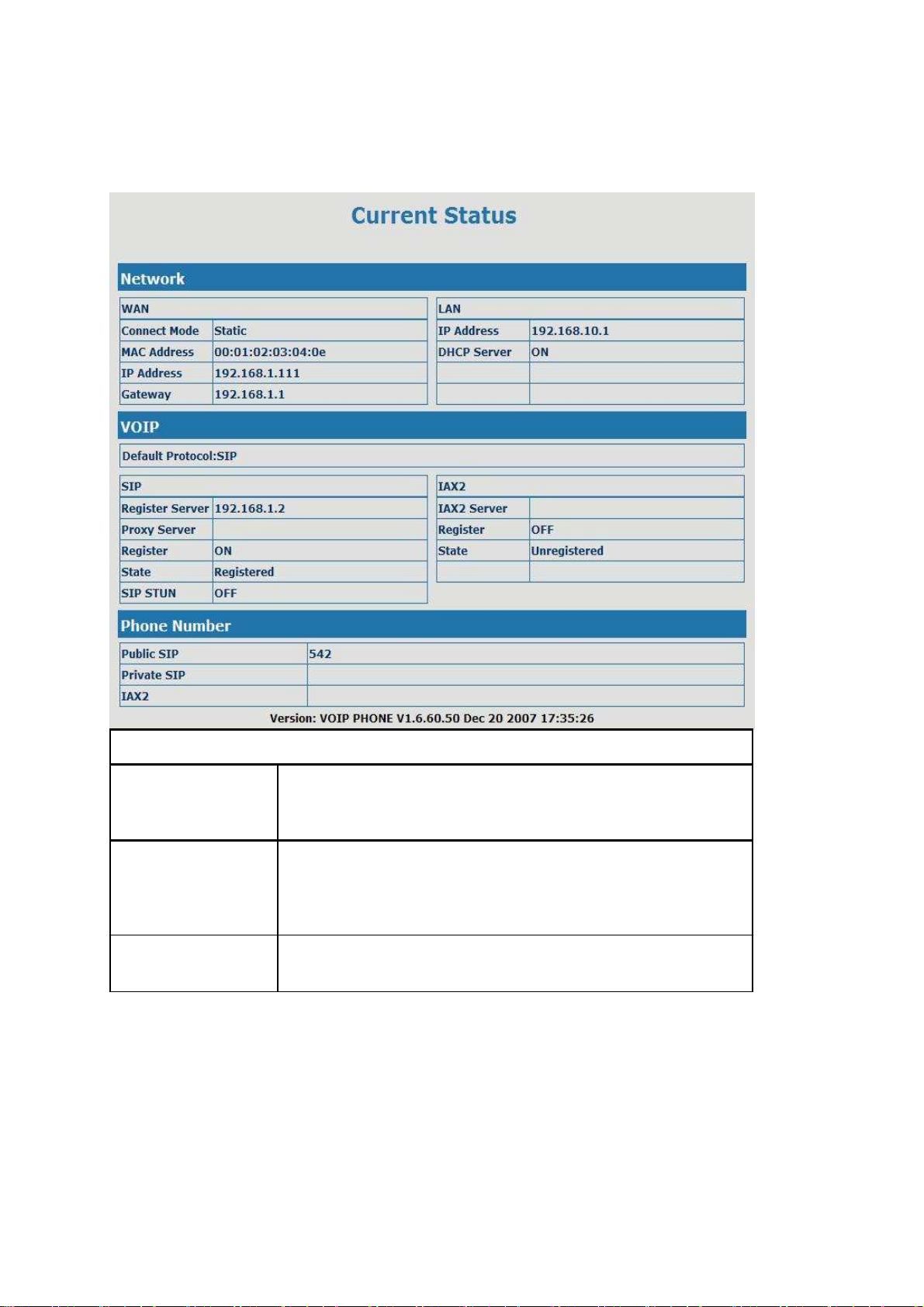
Click on the first submenu “Current status”, you will enter in the following web interface. In this web
interface, you will see current set parameters, status, and the firmware version.
Current Status
Shows the configuration information on WAN and LAN port,
Network
VoIP
Phone Number
including the connect mode of WAN port (Static, DHCP, PPPoE),
MAC address, the IP address of WAN port and LAN port, ON or OFF
of DHCP mode of LAN port.
Shows the current protocols of the phone, and some parameters of
every protocol. You can know about IP addresses of register servers
of both IAX2 and SIP, proxy server IP address, whether start to
register the SIP and IAX2 servers or not, whether be registered or
unregistered, and whether start to register the STUN server.
Shows the phone numbers provided by the SIP, SIP2 and IAX2
servers.
The last line shows the version number and issued date.
14

4.2.2. Network
4.2.2.1. WAN Config
Active IP
Current Netmask
MAC Address
Current Gateway
Mac Authenticating
Code
WAN Config
The current IP address of the phone
The current Netmask address
The current MAC address of the phone
The current Gateway IP address
Set the corresponding authenticating code of MAC. If you don’t
pass the authentication, then it will show “invalid MAC”, at this
time, phone will have no sound while the network is normal.
If you use static mode, you need set it.
IP Address
Netmask Input the IP address distributed to you.
Input the Netmask distributed to you.
15

Gateway
DNS Domain
Primary DNS
Alter DNS
Input the Gateway address distributed to you.
Set DNS domain postfix. When the domain which you input can
not be parsed, gateway will automatically add this domain to the
end of the domain which you input before and parse it again.
Input your primary DNS server address.
Input your standby DNS server address.
Please select the proper network mode according to the network condition. this VoIP Phone
provide three different network settings:
Static: If your ISP server provides you the static IP address, please select this mode, and
then finish Static Mode setting. If you don’t know about parameters of Static Mode
setting, please ask your ISP for them.
DHCP: In this mode, you will get the information from the DHCP server automatically;
need not to input this information artificially.
PPPoE: In this mode, your must input your ADSL account and password.
You can also refer to 2.2. Initial Setting to speed setting your network.
If you uses PPPoE mode,you need to make the above setting.
PPPoE Server
User
Password
Notice:
It will be provided by ISP.
Input your ADSL account.
Input your ADSL password.
1)Click “Apply” button after finished your setting, IP Phone will save the setting automatically
and new setting will take effect.
2)If you modify the IP address, the web will not response by the old IP address. Your need
input new IP address in the address column to logon in the phone.
3)If networks ID which is distributed by DHCP server is the same as network ID which is used
by LAN of system, system will use the DHCP IP to set WAN, and modify LAN’s networks
ID(for example, system will change LAN IP from 192.168.10.1 to 192.168.11.1) when
system uses DHCP client to get IP in startup; if system uses DHCP client to get IP in
running status and network ID is also same as LAN’s, system will refuse to accept the IP to
configure WAN. So WAN’s active IP will be 0.0.0.0
4.2.2.2. LAN Config
LAN Configuration
LAN IP
Netmask specify LAN static IP
specify LAN Netmask
16
DHCP Service
NAT
Bridge Mode
Select the DHCP server of LAN port or not. After you modify the
LAN IP address, gateway will amend and adjust the DHCP Lease
Table and save the result amended automatically according to the
IP address and Netmask. You need restart the phone and the DHCP
server setting will take effect.
Select NAT or not
Select Bridge Mode or not: If you select Bridge Mode, the phone
will no longer set IP address for LAN physical port,LAN and WAN
will join in the same network. Click “Apply”, the phone will
reboot.
Notice: If you choose the bridge mode, the LAN configuration will be disabled.
4.2.3. VoIP
4.2.3.1. SIP Config
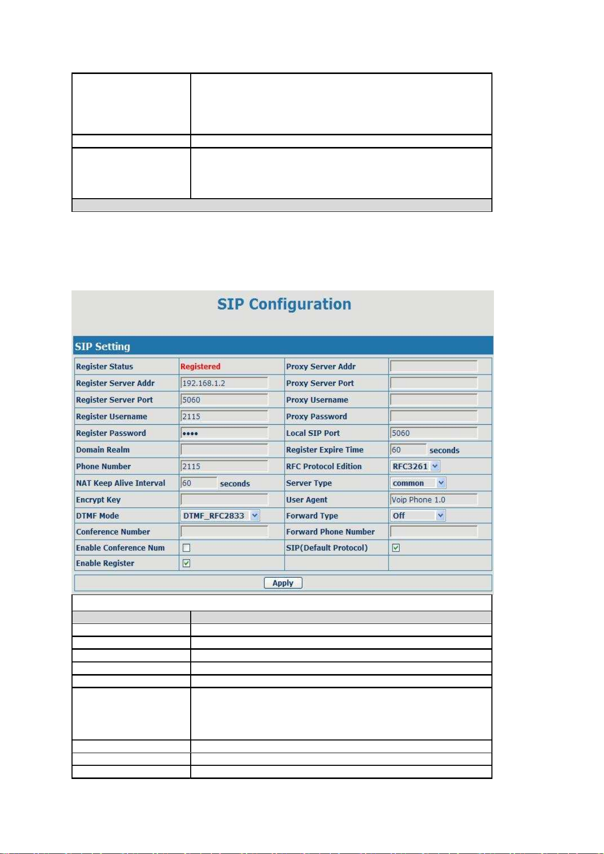
Set your SIP server in the following interface
SIP Config
Filed name
Register Status Illumination
Shows if the phone has been registered the SIP server or not.
Register Server Addr Input your SIP server address.
Register Server Port
Register Username
Register Password
Proxy Server Addr
Proxy Server Port
Proxy Username
Proxy Password
Set your SIP server port.
Input your SIP register account name.
Input your SIP register password.
Set proxy server IP address ( Usually, Register SIP Server
configuration is the same as Proxy SIP Server. But if your VoIP
service provider give different configurations between Register SIP
Server and Proxy SIP Server, you need make different settings.)
Set your Proxy SIP server port.
Input your Proxy SIP server account.
Input your Proxy SIP server password.
17

Local SIP Port
Domain Realm
Phone Number
Register Expire Time
NAT Keep Alive
Interval
RFC Protocol Edition
DTMF Mode
Server Type
Encrypt Key
User Agent
Forward Type
Conference Number
Set your Local SIP port, the default is 5060.
Set the sip domain if needed, otherwise this VoIP Phone will use the
proxy server address as sip domain automatically. (Usually it is
same with registered server and proxy server IP address).
Input the phone number assigned by your VoIP service provider.
Phone will not register if there is no phone number configured.
Set expire time of SIP server register, default is 60 seconds. If the
register time of the server requested is longer or shorter than the
expire time set, the phone will change automatically the time into
the time recommended by the server, and register again.
Set examining interval of the server, default is 60 seconds.
Select SIP protocol version to adapt for the SIP server which uses
the same version as you select. For example, if the server is
CISCO5300, you need to change to RFC2543, else phone may not
cancel call normally. System uses RFC3261 as default.
Select DTMF sending mode, there are three modes:
DTMF_RELAY
DTMF_RFC2833
DTMF_SIP_INFO
Different VoIP Service providers may provide different modes.
Select the special type of server which is encrypted, or has some
unique requirements or call flows.
Set the key for encryption
Set the user agent if have, the default is VoIP Phone 1.0
Select call forward mode, the default is Off
Off:Close down calling forward
Busy:If the phone is busy, incoming calls will be forwarded to
the appointed phone.
No answer:If there is no answer, incoming calls will be
forwarded to the appointed phone.
Always:Incoming calls will be forwarded to the appoint
phone directly, and the phone will not ring.
Set the special phone number of 3 way calling.
Forward Phone Number Appoint your forward phone number.
Enable Conference Num Enable/Disable the function which uses SIP server to realize 3 way
Enable Register talking, not realized by our system.
Start to register or not by selecting it or not.
SIP(Default Protocol) Use SIP protocol as default dial protocol
18

4.2.3.2. IAX2 Config
Register Status
IAX2 Config
Shows if the phone has been registered the IAX2 server or not.
IAX2 Server Addr Input your IAX2 server address.
IAX2 Server Port
Account Name Set your IAX2 server port, the default is 4569.
Input your IAX2 register account name.
Account Password Input your IAX2 register password.
Phone Number
Local Port
Input your assigned phone number (usually it is same you’re your
IAX2 account name ).
Set your local sport,the default is 4569.
Voice Mail Number Specify the voice mail’s number.
Voice Mail Text
Echo Test Number
Echo Test Text
Refresh Time
Enable Register
Enable G.729
IAX2
(Default Protocol)
Specify the voice mail’s name.
Set echo test number. If IAX2 server supports echo test, and echo test
number is non- numeric, system could set an echo test number to
replace the echo test text. So user can dial the numeric number to test
echo voice test. This function is provided with server to make
endpoint to test whether endpoint could talk through server normally.
Specify echo test text’s name.
Set expire time of IAX2 server register, you can set it between 60 and
3600 seconds.
Start to register the IAX2 server or not by selecting it or not.
Enable or disable code G.729 by selecting it or not
Select it to make all outgoing calls through the IAX2 server by
default. If you also need make a call through SIP server, you can
make prefix in dial peer setting to realize SIP calling.
Note: any incoming call can be from both IAX2 and SIP.;
19

4.2.4. Advance
4.2.4.1. DHCP Service
DNS Relay
DHCP Service
Select DNS Relay, the default is enable. Click the Apply button to
become effective.
Shows the DHCP Lease Table,the unit of Lease time is Minute.
Lease Table Name
Start IP
End IP
Netmask
Gateway
Lease Time
DNS
Specify the name of the lease table
Set the start IP address of the lease table
Set the end IP address of the lease table, the network device
connected to LAN port will get IP address between Start IP and End
IP by DHCP.
Set the Netmask of the lease table
Set the Gateway of the lease table
Set the Lease Time of the lease table
Set the default DNS server IP of the lease table
Click the Add button to submit and add this lease table
Select name of lease table, click the Delete button will delete the selected lease table from
DHCP lease table.
Notice:
1)The size of lease table can not be larger than the quantity of C network IP address. We
recommend you to use the default lease table and not modify it.
2)If you modifies the DHCP lease table, you need save the configuration and reboot.
20
Table of contents


