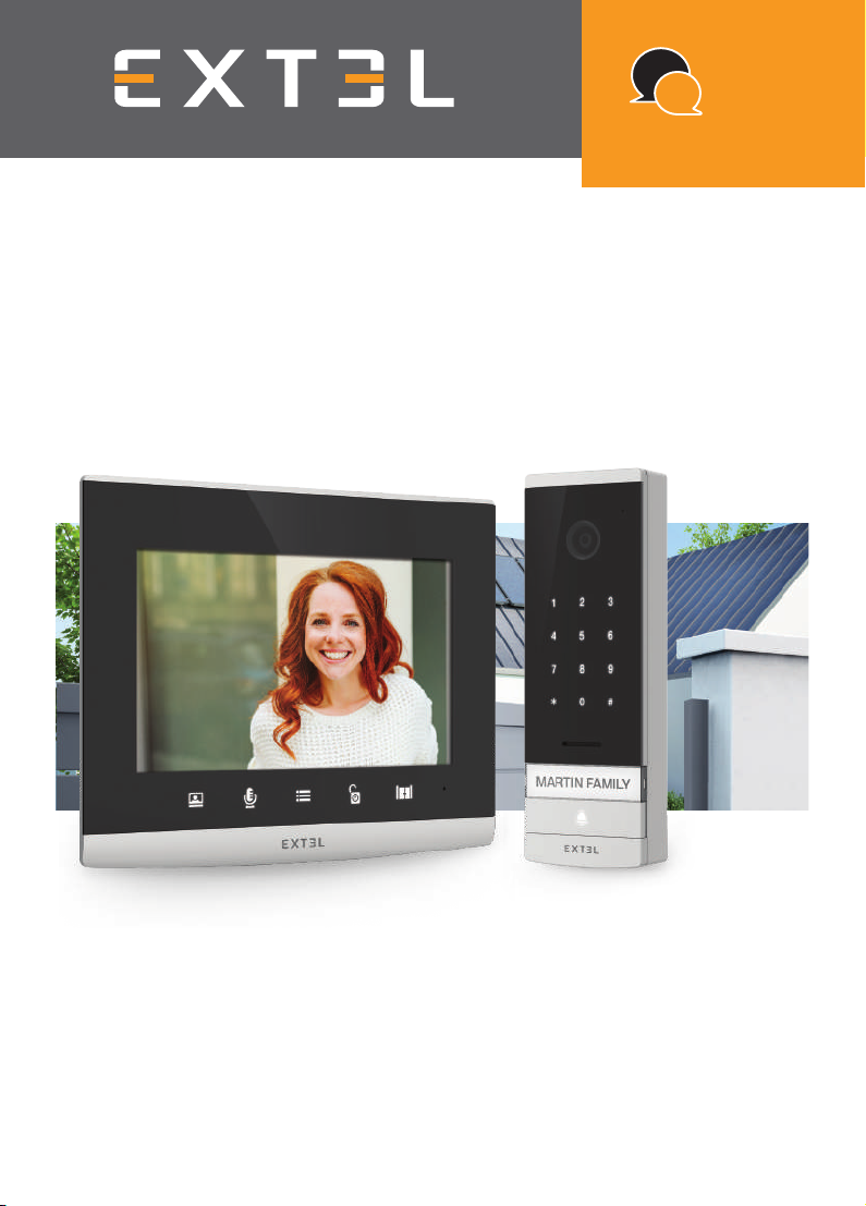
EXTEL - CODE CONNECT - 720320
en - 3
D - INSTALLATION
1 - WIRING
• The wiring diagrams for the various configurations can be found in:
- Fig. 7: 1 family – 1 monitor
- Fig. 8: 1 family – 2 monitors
-Fig9: 2 families – 1 monitor in each (2 monitors in total)
• Do not increase the number of insulating screw joints or connectors on the connecting wire between the
intercom panel and the monitor
• In order to avoid the risks of interference and malfunction, do not pass the wire for your videophone through the
same sheath as the electrical wires.
• Keep the connecting wire between the intercom panel and the monitor more than 50cm away from any
electromagnetic interference (230V cable, WiFi equipment, microwave ovens, etc.).
• You can connect and use the electric door release (not provided) with your intercom panel, with or without
mechanical memory.
• To ensure good audio and video quality, it is advised to not use more than 100m of cable between the intercom
and the intercom panel. The cable size to be used is shown in Fig. 10
Warning: Do not under any circumstances double wires to increase the wire size.
• If a wire is incorrectly connected or disconnected after powering up, the entire system must be disconnected
before any intervention. Your gate can be connected to the power supply again once the defective connection
has been repaired.
Note: if you are testing the product prior to installing it, it is recommended that you place the unit on a flat surface.
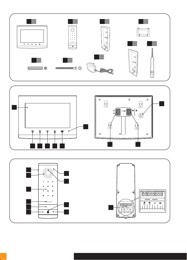
2 - INSTALLING THE INTERCOM PANEL
Note: If you test your product before installing it, put the monitor on a flat surface and make sure not to test it with
the intercom panel and the monitor in the same room. If you do so, the videophone will emit a piercing sound
(feedback effect).
Installing the intercom panel (fig. 4, 5.1 and 5.2)
• Remove the screw under the intercom panel (1)
• Tilt the intercom panel forwards (2)
• The lens of the panel must be placed at a height around 1.60 m (5).
• Firmly attach the weather-proof shield with screws (2) and apply a silicon seal (3) between the shield and the
wall to prevent water from running between the two. *Do not use acetic acid-based silicone (vinegar odour).
• After wiring, fit the intercom panel onto its weather-proof shield (4).
• Re-install the attachment screw (5).
Important: Do not have the camera directly exposed to the sun or facing a reflective surface. At
the same time, remember to properly insert the intercom panel lug in the hole on the weather-proof
shield.
Tip: it is recommended that the wires be passed through a sheath to protect them from
impacts and weather.
Installing the monitor (fig. 4, 6.1 and 6.2)
• Attach the wall bracket so that the screen of the monitor will be around 1.60 m high.
• Connect the wires coming from the intercom panel.
• Insert the adapter wires in the back of the monitor (without plugging it into the wall socket).
Warning you must comply with the polarity (red and black terminals).