Socal Moto Gear GL18FGN User manual

© Copyright 2015 SoCalMotoGear. All Rights reserved. Ver. 1.5 Page 1 of 4
INSTALLATION INSTRUCTIONS
GL1800 LED FOG LIGHT KIT
2001-2010 PART NO. GL18FGN (NON-AIRBAG)
2006-2010 PART NO. GL18FGA (WITH AIRBAG)
2012+ PART NO. GL18FGA (WITH OR WITHOUT AIRBAG)
L.E.D.
Congratulations on your purchase!
This product is intended for aftermarket use and have been fit checked on stock, non-modified OEM motorcycles. As with any aftermarket products,
there may be some slight modifications required. In some cases, minor modifications such as drill-out of a bigger hole may be necessary on the part
itself or onto your motorcycle. If you are not comfortable with any installation steps, please consult a qualified motorcycle technician to perform the
work. Always allow bulbs to cool down before touching them.
Non U.S. Motorcycles: This kit may not be Plug and Play on non U. S. spec motorcycles.
PARTS LIST
LETTER
QTY
LED FOG LIGHT
A
2
RIGHT MOUNTING BRACKET
B
1
LEFT MOUNTING BRACKET
C
1
4MM SPACER
D
3
20MM SPACER
E
1
16MM SPACER
F
2
SMALL FLANGE INSERT
G
4
M5 X 18MM SCRW
H
4
LARGE FLANGE INSERT
I
6
LARGE RUBBER GROMMET W/BRACKET
J
6
2MM SPACER
K
6
M6 FLANGE (LONG) BOLT
L
3
M6 FLANGE (SHORT) BOLT
M
3
JUMPER WIRE [non-pictured]
--
1
SPRING
N
2
M5 X 30MM SCREW [non-pictured]
--
2
FLAT WASHER
O
6
SMALL RUBBER GROMMET W/LIGHT BRACKET [non-pictured]
--
4
ZIP TIE
P
1
ON/OFF SWITCH
Q
1
FOG LIGHT WIRE HARNESS
R
1
INSTALLATION STEPS:
STEP 1. Place motorcycle on center stand.
IMPORTANT –The memory settings of the suspension system, trip meter, clock, and radio will be lost when disconnecting the negative battery cable.
Reset your settings after reconnecting the battery.
STEP 2. Disconnect the negative cable from the battery.
STEP 3. Remove the lower front cowl following the repair manual instructions.
STEP 4. Skip this step if you currently have fog lights installed. Remove your existing lights and proceed to Step 5.
Using cutters, remove the plastic knockouts from the lower front cowl and smooth edges with a Dremel® or file.
STEP 5. Locate the Left (indicated on the back with an “L”) and the Right (indicated on the back with an “R”) Mounting brackets and set aside.
To see our Installation Video, please visit: www.SoCalMotoGear.com/foglights
(A)
(F)
(K) (B)
(D)
(M)
(I)
(D)
(I)
(E)
(N)
(I)
(J)
(K)
(L)
(G)
(H)
(R) (Q)
(P)
(J)
(C)
(O)
(O)
© Copyright 2015 SoCalMotoGear. All Rights reserved. Ver. 1.5 Page 2 of 4
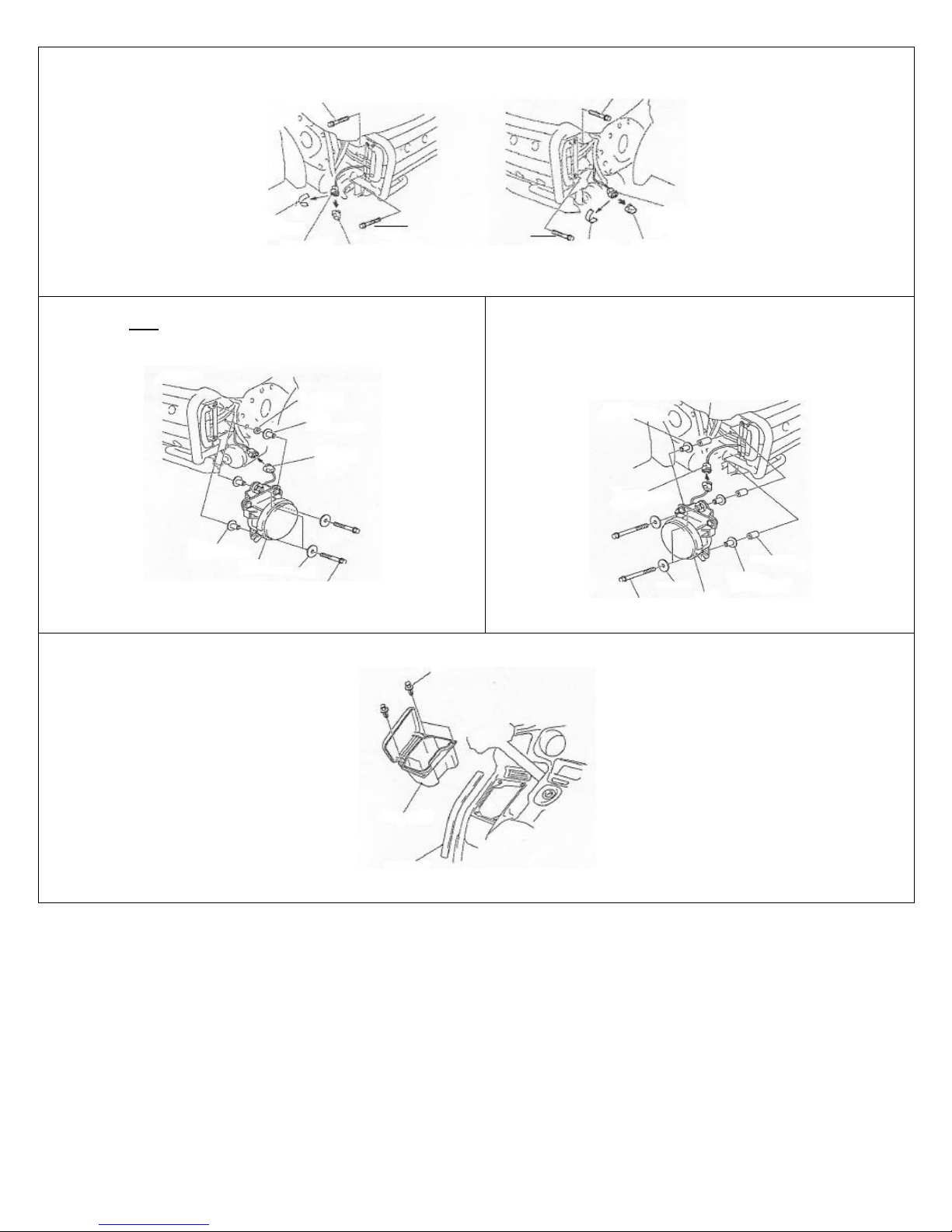
STEP 6. Remove part as shown.
STEP 7. Install Right fog light as shown. Using three Short M6 Flange Bolts,
Flat Washers, 4mm Spacers (for 2001-2005 models) and Plastic Trim Piece.
STEP 8. Install Left fog lights as shown, using three Long M6 Flange
Bolts, Flat Washers, Two 20mm spacers on top and side bolts, and one
16mm spacer for bottom bolt.
Note: Extra 2mm spacers are included in this kit. You can use as needed.
STEP 9. Remove part as shown.
NOTE: The unit is plug n play and included is a Relay and Jumper plugs. If the relay is used, the kit will function as OEM and the fog lights will turn off
with the high beams. If the jumper plug is used, the fog lights will work with both low and high beam headlights.
RIGHT 4MM Spacer
Large Flange insert
2-PIN Connector (gray)
Large Flange Insert
RIGHT FOG LIGHT
2MM Spacer
M6 Flange Bolt (short)
LEFT 20MM Spacer
Large Flange Insert
2-PIN Connector (gray)
16MM Spacer
2MM Spacer Large Flange Insert
M6 Flange Bolt (long) LEFT FOG LIGHT
CLIP
Left Pocket
Left Cowl Trim Molding
LEFT RIGHT
BOLT (save) BOLT (save)
TAPE
Remove to free
the connector. BOLT (save)
ACCESSORY 2-PIN DUMMY
(Gray) CONNECTOR (save)
BOLT (save)
Dummy Connector
Tape –Remove to (save)
free the connector.

© Copyright 2015 SoCalMotoGear. All Rights reserved. Ver. 1.5 Page 3 of 4
FOLLOW STEPS BELOW FOR 2001-2011 AND NON-AIRBAG MODELS
STEP 10. Remove the Left Control Panel.
STEP 11. Remove the Switch Cover and Switch Hole Cover. Install the
Switch on the Left Control Panel.
STEP 12. Plug the 4-pin switch connector into the relay harness. Then plug
the relay harness into the motorcycle’s accessory 4-pin connector
NOTE: This kit comes with the jumper plug. When using the jumper plug,
the fog lights will only turn off with the switch.
STEP 13. Re-install the left control panel and side molding in the reverse
order of removal.
STEP 14. Connect the negative battery cable.
STEP 15. Place the motorcycle on level ground, approximately 16 feet away
from a wall.
STEP 16. Turn on the fog light.
STEP 17. Measure the height from the ground to the center of fog light.
STEP 18. Using a pencil, make a mark of the fog light mounting height on
the wall.
STEP 19. Screw in or out the adjustment screw on each mounting bracket
to aim the fog light (see image).
IMPORTANT LIGHT ADJUSTMENT TIP:
If the fog light is shining to high after installation, screwing “in” will lower
the light.
STEP 20. Reinstall the front lower cowl in the reverse order of removal.
****FOR 2012+ AIRBAG MOTORCYCLE MODELS, SEE NEXT PAGE. ****
Mounting Height
of Fog Lamp
16’ ft
CUT-OFF LINE
Mounting
Height of
Fog Lamp
Screw (re-use)
LEFT CONTROL PANEL (re-use)
Screw (re-use) Switch Hole Cover (save)
Screw (re-use)
SWITCH
SWITCH COVER (re-use)
LEFT CONTROL PANEL
MOTORYCLE’S CONNECTOR COVER
Accessory 4-pin Connector (black)
LEFT CONTROL PANEL SUB HARNESS
LEFT CONTROL PANEL
WIRE TIE SUB HARNESS RELAY
Secure with zip ties.

© Copyright 2015 SoCalMotoGear. All Rights reserved. Ver. 1.5 Page 4 of 4
FOLLOW STEPS BELOW FOR 2012+ AIRBAG MODELS
STEP 1. Remove the radio control panel.
STEP 2. Remove the cover and cap as shown in image.
STEP 3. Install the fog light ON/OFF switch as shown.
STEP 4. Re-install the cover in the reverse order or removal. Then route
the harness as shown.
STEP 5. Plug the 4-pin switch connector into the relay harness. Then plug
the relay harness into the motorcycle’s accessory 4-pin connector.
STEP 6. Using the supplied zip ties, secure the relay and sub-harness.
STEP 7. Place the relay and Fog Light Sub Harness in the gap as shown in
image.
STEP 8. Re-install the Radio Control Panel and Left Cowl Trim molding in
the reverse order of removal.
Condensation:
Light condensation is completely normal after riding in cold/wet
weather and should disappear after a few days. Heavy condensation is
water/moisture that remains inside the lens and did not evaporate after
a week. In this case, it is covered under warranty. See
SoCalMotoGear.com for warranty information.
NOTE: As with many stock and aftermarket parts variations occur that may require slight correction.
Disclaimer: Please follow the instructions and use care and proper judgment when installing this product. Maximum liability is limited to the purchase price of the product sold. Visit
SoCalMotoGear.com for additional warranty information.
BOLT
RADIO CONTROL
PANEL
COVER
RADIO CONTROL PANEL
SCREW (save)
CAP (save)
RAIO CONTROL PANEL
Fog light
ON/OFF Switch
SCREW (re-use)
FOG LIGHT HARNESS
RADIO CONTROL PANEL
CONNECTOR COVER
ACCESSORY 4-PIN CONNECTOR (Black)
RELAY
Zip Tie
FOG LIGHT
SUB HARNESS
RELAY
Secure in this gap area.
FOG LIGHT
SUB HARNESS
This manual suits for next models
1
Table of contents


