Menvier Beamlite User manual

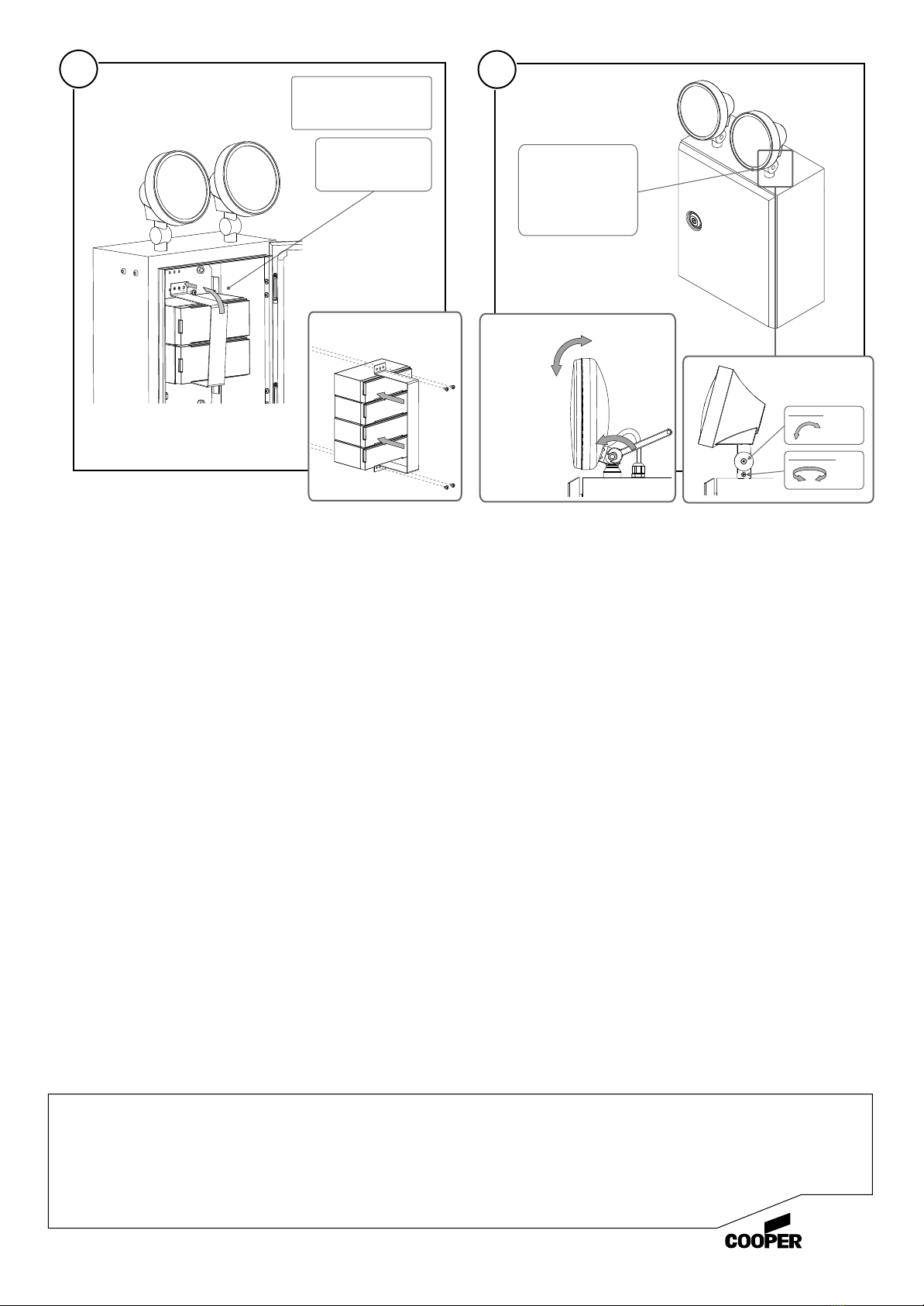
Open door, unscrew
battery clamp, then
remove clamp and
batteries
Check that nylon/steel nuts
are securely tightened
on underside of lamp heads
Mount fitting to
surface using
4 x fixing screws
(not supplied)
Removing batteries
Important Note: Wiring
Mounting
Ensure mains supply is turned OFF
Wire mains cable into terminal block as shown below:
FITTING MUST BE EARTHED
L
N
- Brown (Live)
- Green/Yellow (Earth)
- Blue (Neutral)
1 2
3 4
F
IP55
Beamlite
Installation Instructions for:
!Product luminaires comply with BS 60598-2-22 Class 1.
oo
!This luminaire has an ambient temperature range of 5 C to 25 C
270.0mm
215.0mm
Mounting Holes
Loosen 4 x screws
to remove clamp
and batteries
For 55W Version
MENVIER
K884V1
Cooper Lighting and Safety Ltd
Wheatley Hall Road, Doncaster, South Yorkshire, DN2 4NB
Sales General Major Projects London International Sales
T: +44 (0)1302 303303 +44 (0)1302 321541 +44 (0)1992 787999 +44 (0)1302 303250
F: +44 (0)1302 367155 +44 (0)1302 303220 +44(0)1992 787222 +44 (0)1302 303251
Lighting
Replace batteries,
fit one side of clamp
then secure other side
with fixing screw
Batteries must be linked
using wires provided in bag,
refer to label on inside of
the door for wiring details
To adjust lamp head
position, loosen
screws/nut on side of
each head to either tilt
or rotate head, tighten
screw/nut to lock in
position
Replace batteries Adjusting lamp heads
5 6
Top screw
Tilt
Rotate
Bottom screw
Caution:
after installation. In accordance with IEE regulation 613-7 and ECA/LIF recommendations
disconnect live and neutral wire from unit before insulation resistance check.
Testing:
Connect mains supply and ensure that the battery leads are connected to the batteries. It is recommended that a full duration test is
carried out. Connect the unswitched live for 24 hours. This will fully charge the battery. Check that both LED indicators glow red and
the lamp filaments are intact.
After 24 hours disconnect the supply and check that both lamps light in the emergency mode and stay lit for at least the rated
discharge period.
If it is not possible to conduct a full duration test as above then charge for a minimum of 1 hour after which
the lamps should light for a period of a few minutes.
DO NOT INSULATION TEST (MEGGA)
Routine Testing:
The unswitched supply should be interrupted once a month for a short period to ensure that the emergency circuit is operating. In
addition, after 12 month from date of commissioning and subsequently annually a full rated discharge test must be performed. If
any tests are not performed satisfactorily they should be repeated after a full 24 hour recharge period. If the unit no longer meets
the emergency duration the battery must be replaced.
Warning:
When disposing of batteries, do not pierce or incinerate. The batteries should be disposed of in accordance with the recognised
disposal methods.
Additional notes on INSTALLATION FOR ELECTROMAGNETIC COMPATIBILITY
The intended use of this product is to supply rated illumination for its specified duration in the event of a failure of the mains supply.
During normal mains healthy conditions, the batteries are charged. When used as intended this product complies with EMC Directive
(89/336/EEC) and the UK EMC regulations 1992 (SI 2372/1992) by meeting the limits set by the standards BS 5306 Pts 2 + 3 1988,
EN50082-1 1992 and EN50081; 1992. The following installation guidelines must be followed:
1. External cables must be connected using the cable entries.
2. When routing external cables inside the product they must be:
a) Kept as short as possible.
b) Routed close to the housing.
c) Kept as far as possible from the electronics.
Any modifications other than those in this installation leaflet, or any other use of the product may cause interference and is the
responsibility of the user, who should ensure compliance with the EMC and Low Voltage Directives.
For 55W Version
For 55W Version
To tilt head,
loosen nut
on side
To rotate head
loosen nut on
under side of
head inside
the box


