SODECA CORTINA COMERCIAL COM-B-100-V User manual

Code: 1189001
Doc. Num: 0000013658 (06-03-2019)
www.sodeca.com
CORTINA
COMERCIAL
ES
EN
Manual del Usuario
User Manual

Fig. 1
Fig. 2
Fig. 3
Fig. 4
ES
EN
1
Soportes de montaje
Mounting brackets
2
Cuerpo de la cortina
Curtain body
3
Sección para conectar el
módulo de control
Area to connect the control
module
4
Cubierta de succión
Suction cover
5
Conexión del intercambiador de
agua (sólo versiones con
batería de agua)
Water coil connection zone
(only water coil versions)
6
Cubierta lateral
Side cover
7
Caja de bornes para la
conexión del suministro de
energía.
Terminal box for main power
connection

Fig. 5
Fig. 6
Fig. 7
Fig. 8
Fig. 9
Fig. 10
Fig. 11

Fig. 12
Fig. 13
Fig. 14
Fig. 15
Fig. 16
Fig. 17

ON REQUEST
Fig. 18
Fig. 19
Fig. 20
Fig. 21
Fig. 22
Características técnicas batería de agua y accesorios válvulas 3 vías /
Technical characteristics water battery and accessories 3-way valves
Temperature gradient 80/60ºC
Temperature gradient 60/40ºC
Model
Airflow ref.
[m3/h]
Heat
power
[kW]
Output
temp.
[ºC]
Loss of
load [kPa]
Water
flow
[l/s]
Heat
power
[kW]
Output
temp.
[ºC]
Loss of
load [kPa]
Water
flow
[l/s]
Accesory
or 3 way
valve
COM-B-100-V
1500
14,1
46,2
10,3
0,62
8,27
34,5
4,12
0,36
ZV-3
COM-B-150-V
2250
20,58
45,4
7,26
0,9
11,86
33,8
2,75
0,52
ZV-3
COM-B-200-V
3300
29,79
45,1
10,59
1,31
17,26
33,7
4,02
0,75
ZV-3
COM-B-250-V
3800
36,22
46,6
16,68
1,59
21,33
34,8
6,47
0,93
RT-3-15
COM-C-100-V
2300
18,59
42,2
16,97
0,82
10,71
32
6,57
0,47
ZV-3
COM-C-150-V
3200
26,36
42,7
11,48
1,16
14,97
32
4,22
0,65
ZV-3
COM-C-200-V
4500
36,93
42,6
15,79
1,62
21,06
32
5,79
0,92
RT-3-15
COM-C-250-V
5700
44,8
41,6
24,72
1,97
26,03
31,7
9,42
1,14
RT-3-15

ON REQUEST
Fig. 23
Características técnicas / Technical characteristics
Model
Height
door
Maximum
airflow
LpA 5m
Power supply
Power/Total
current
Power/Fan
current
Heater power
[kW]
Increase
temp.
Weight
[m]
[m3/h]
dB(A)
[V]/[HZ]
[kW] / [I]
[W] / [I]
1ª etapa
Máx.
[ºC]
[Kg]
COM-B-100-S
4
1500
53,8
1x230 / 50
0,12 / 0,6
120 / 0,6
-
-
-
24,8
COM-B-150-S
4
2250
55,1
1x230 / 50
0,2 / 0,9
200 / 0,9
-
-
-
31,3
COM-B-200-S
4
3300
56,8
1x230 / 50
0,3 / 1,4
305 / 1,4
-
-
-
38,3
COM-B-250-S
4
3800
58,6
1x230 / 50
0,4 / 2,0
410 / 2,0
-
-
-
45,1
COM-B-100-E
4
1500
53,8
3x400 / 50
6,5 / 13,8
120 / 0,6
3,2
6,3
13,2
25,5
COM-B-150-E
4
2250
55,1
3x400 / 50
10,2 / 21,8
200 / 0,9
5,0
10,0
13,3
32,6
COM-B-200-E
4
3300
56,8
3x400 / 50
13 / 27,5
305 / 1,4
6,3
12,6
12,0
39,8
COM-B-250-E
4
3800
58,6
3x400 / 50
16,8 / 26,2
410 / 2,0
8,2
16,3
13,1
46,9
COM-B-100-V
4
1500
53,8
1x230 / 50
0,12 / 0,6
120 / 0,6
-
16,9
33,7
26,1
COM-B-150-V
4
2250
55,1
1x230 / 50
0,2 / 0,9
200 / 0,9
-
24,7
32,9
32,9
COM-B-200-V
4
3300
56,8
1x230 / 50
0,3 / 1,4
305 / 1,4
-
35,7
32,5
40,1
COM-B-250-V
4
3800
58,6
1x230 / 50
0,4 / 2,0
410 / 2,0
-
43,3
34,2
47,4
COM-C-100-S
5
2300
64,5
1x230 / 50
0,33 / 1,5
325 / 1,5
-
-
-
26,3
COM-C-150-S
5
3200
65
1x230 / 50
0,42 / 1,9
420 / 1,9
-
-
-
35,7
COM-C-200-S
5
4500
64
1x230 / 50
0,63 / 3,3
630 / 3,3
-
-
-
45,8
COM-C-250-S
5
5700
64,2
1x230 / 50
0,85 / 4,4
850 / 4,4
-
-
-
53,1
COM-C-100-E
5
2300
64,5
3x400 / 50
9,9 / 15,4
325 / 1,5
4,7
9,5
12,3
27,3
COM-C-150-E
5
3200
65
3x400 / 50
15,5 / 23,8
420 / 1,9
7,5
15,0
14,0
37,4
COM-C-200-E
5
4500
64
3x400 / 50
19,7 / 30,7
630 / 3,3
9,5
19,0
12,6
47,7
COM-C-250-E
5
5700
64,2
3x400 / 50
25,4 / 38,7
850 / 4,4
12,2
24,5
12,8
55,8
COM-C-100-V
5
2300
64,5
1x230 / 50
0,33 / 1,5
325 / 1,5
-
22,4
29,2
27,6
COM-C-150-V
5
3200
65
1x230 / 50
0,42 / 1,9
420 / 1,9
-
31,8
29,8
39,3
COM-C-200-V
5
4500
64
1x230 / 50
0,63 / 3,3
630 / 3,3
-
44,4
29,6
47,6
COM-C-250-V
5
5700
64,2
1x230 / 50
0,85 / 4,4
850 / 4,4
-
53,7
28,3
55,3

ES
1. Inicio
Todos los ventiladores SODECA, en adelante el fabricante, así como la línea completa de accesorios, han sido
fabricados bajo los estándares más rigurosos de procesos de producción, sistemas y aseguramiento de calidad.
Su estructura de proyecto, ensayos, fabricación y control, está configurada de acuerdo con las normativas de la EU y muy
particularmente en lo referente a las normas de seguridad vigentes.
os materiales empleados y los componentes normalizados que integran nuestros ventiladores, están dentro de los
mismos estándares y amparados, cuando así se requiere, por los certificados de calidad correspondiente.
El Manual Original ha sido redactado en Idioma Español
El fabricante, se reserva el derecho a modificaciones sin previo aviso
Toda la documentación contenida en este manual es propiedad del fabricante y está prohibida su reproducción total o
parcial.
2. Definición de producto
Cortina Comercial: Cortinas de aire para puertas comerciales.
IMPORTA TE: Producto no apto para su uso en atmosferas explosivas o seguridad de incendios, para transportar aire
que contenga mezclas de vapores de productos químicos, hollín, grasas, gérmenes, o cualquier otro producto que pueda
dañar el equipo.
IMPORTA TE: Posibilidad de escoger entre control BASIC o COMFORT
3. Información general
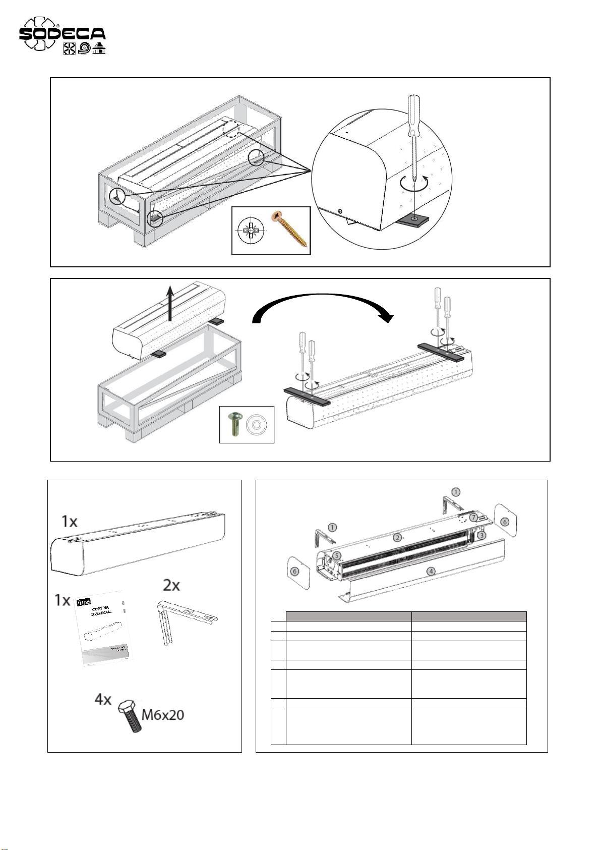
• IMPORTA TE: Antes de retirar la cortina de la tabla, quite la cubierta (Fig.1)
• Verifique siempre los productos recepcionados.
• Después de desembalar el equipo debe comprobarse que no tiene desperfectos. Nunca debe instalar productos
dañados
• No debe usar este equipo para propósitos distintos para los cuales fue diseñado, solo debe operar en las
condiciones citadas en este manual.
• En caso de defecto o mal funcionamiento, debe informarse al representante autorizado, describiendo el problema,
a fin de coordinar su devolución o posible reparación.
• Antes de poner en marcha el equipo, es necesario asegurarse que se ha leído las instrucciones de seguridad e
instalación de este documento y de todos los elementos utilizados.
• En caso de no ser desembalado inmediatamente después de recibirlo, el producto debe ser guardado en un lugar
seco y a resguardo, con una temperatura ambiente de +5ºC a +40ºC y una humidad relativa de hasta 80%.
• Si el producto fue transportado a temperaturas menores a 0ºC, luego de desembalarlo déjelo sin encender al menos
2 horas en condiciones operativas antes de encenderlo. Esto permitirá que la temperatura en el interior del equipo
se desestabilice.
4. Transporte, almacenamiento y manipulación
• Sujetar siempre el equipo por los puntos previstos. No levantar por los cables de alimentación, cajas de bornes y
bocas de impulsión o aspiración.
• Antes de la instalación almacene los equipos en lugar seco, limpio, y resguardado de las inclemencias del tiempo.
5. Seguridad
• No desmonte ni modifique el equipo. Esto puede ser perjudicial para el equipo o incluso ser causa de accidentes.
• No debe introducirse ningún objeto o dedos en las rejillas protectoras de las bocas. Si fuera así, desconecte
inmediatamente la alimentación del equipo.
• Nunca utilice un cable de alimentación si este está dañado.
• No opere el equipo si está instalado de forma forzada sobre una superficie curvada o inestable.
• No efectuar operaciones de inspección o mantenimiento del equipo sin antes asegurarse de:
o Haberlo desconectado de su acometida eléctrica.
o Que todos sus elementos estén en reposo.
• No debe operarse el equipo sin que haya sido correctamente instalado y protegidas las bocas de aspiración e
impulsión, en caso necesario.
• Para garantizar que la distancia entre las superficies de la estructura de obra y los objetos de materiales inflamables
es segura, será de aplicación lo siguiente (Fig. 7):
o a distancia segura de los materiales inflamables en el sentido del flujo principal de aire (antes de la rejilla
de succión y tras la turbina de extracción) debe ser de 500mm.
o Se considera que la distancia segura de los materiales inflamables sobre la cortina de aire es de 500mm.
o Se considera que la distancia segura de los materiales inflamables en el resto de sentidos es de 100mm.

ES
as diferentes Series de Cortinas de aire del fabricante, han sido diseñados y fabricados teniendo en cuenta la particularidad
de Eliminación de Riesgo, para cumplir las condiciones de Seguridad Integrada.
Cuando su configuración y proceso de fabricación lo permiten, el fabricante incorpora directamente los dispositivos de
seguridad más adecuados. Si por sus condiciones de montaje o aplicación, ello no es posible en su origen, se dispone de
todos los accesorios adicionales de Seguridad, para que sean implementados en el momento de su Instalación antes de la
entrada en servicio.
6. Instalación
a instalación sólo debe ser realizada por personal calificado, familiarizado con la instalación, supervisión y mantenimiento
de este tipo de equipos, usando las herramientas adecuadas.
Mecánica
• a fijación del equipo debe ser firme para asegurar una operación segura.
• a unidad se debe instalar únicamente en posición horizontal.
• Puede fijar el equipo de distintas formas. (Fig. 5 y 6) (Las fijaciones mencionadas no se incluyen con la cortina)
• as varillas roscadas para fijar el equipo no forman parte del suministro, deberán proveerse por cuenta del cliente.
• Para la fijación del equipo en pared debe utilizar el soporte señalado en la figura 5. El equipo de soporte de pared
se suministra por separado.
• Para la fijación del equipo en techo debe utilizar el soporte señalado en la figura 6. El equipo de soporte para techo
se suministra por separado.
• IMPORTA TE: a suspensión debe soportar el peso de la cortina de aire. (Fig. 7)
• a cortina puede instalarse sobre la apertura de la puerta. Todas las distancias de separación para los materiales
inflamables y el uso seguro de las cortinas de aire deben respetarse.
• a unidad puede instalarse encima de la puerta. Se debe mantener las distancias con materiales inflamables para
el uso seguro de la cortina de aire.
• Sólo puede haber materiales no inflamables (que no se quemen, no ardan, no sean de carbón) o materiales
resistentes al fuego (que no se quemen, principalmente que no ardan, como por ejemplo el cartón yeso) a una
distancia de hasta 100 mm de la cortina de aire en cualquier dirección. No obstante, dichos materiales no deberán
bloquear las aperturas de entrada ni de salida.
• Es necesario que la instalación impida contacto con la turbina del ventilador, mediante la aplicación de rejillas
accesorios o instalando una tubería de conexión de longitud adecuada.
• Finalizado el montaje mecánico, se tiene que verificar que la hélice o turbina gire libremente, sin roces ni tensiones.
Eléctrica
• IMPORTA TE: Para realizar la instalación eléctrica es necesario utilizar el manual de instalación del control de la
cortina de aire.
• Asegúrese que el equipo está conectado a la fuente de alimentación de acuerdo con las indicaciones del esquema
de conexión de este documento (Intercambiador de agua, motores y calentador eléctrico).
• Seleccione un cable de alimentación con una sección acorde con la intensidad del equipo.
• IMPORTA TE: Cuando el equipo es controlado reduciendo la tensión, la intensidad del motor puede ser superior
a la nominal.
• Verifique que las características eléctricas de la placa corresponden con las de la red de alimentación.
• Es necesario conectar un elemento de protección externo (relé, magneto térmico o fusible), según el reglamento
vigente.
• as cortinas de aire están equipadas de un fusible (fusible de acción retardada con característica T). Este fusible
protege el panel electrónico y el ventilador. Se encuentra ubicado bajo la tapa de servicio, junto a los conectores
de alimentación.
• Debe conectarse la toma de tierra del equipo.
• os esquemas eléctricos del producto priman sobre los presentados en este manual.
• a cortina de aire deberá ser conectada mediante el sistema TN-S, lo que significa que el conductor neutro siempre
deberá estar conectado.
Conexión de las conducciones de agua
• as cortinas provistas de batería de agua requieren de una conexión de G3/4. (No subministrado con el equipo)
• a temperatura máxima del agua es de +100ºC y la presión máxima es de 1.6 MPa. Se recomienda instalar una
válvula de tope de entrada y salida para permitir la desconexión del suministro de agua.
• IMPORTA TE: Al conectar el calentador, sostenga la toma con pinzas para evitar daños. (Fig. 20)

ES
Fijación de la cortina en el techo
• Antes de proceder con el montaje, cerciórese que la estructura tiene suficiente solidez para aguantar el peso del
equipo. (Fig. 7)
• Fije las varillas al techo. (Fig. 8)
• Fije las varillas a la cortina. (Fig. 9)
Instalación del módulo de control
• Retire la placa lateral sujeta al motor con dos tornillos M5
• Inserte el módulo en la unidad
• Ajuste la caja de bornes con la herramienta
• Tensione el bloque de terminales con unas punzas Siko
Puesta en marcha
• IMPORTA TE: Apunte el escape a la dirección deseada durante la instalación. El escape de la cortina puede soplar
aire en un ángulo máximo de 15º. (Fig. 21)
• Después de poner en marcha el equipo, es necesario asegurarse que el motor está girando correctamente, sin
vibraciones y no provoca ruidos fuera de lo normal.
• Compruebe el comportamiento del ventilador mediante el uso de elementos de control externos, así como la
regulación del calentador eléctrico o del calentador de agua.
• Es necesario comprobar que el consumo real del motor no excede a lo indicado en la etiqueta del equipo y éste no
sufre calentamiento excesivo.
• No debe conmutar el encendido de forma intermitente, de modo que se pueda dañar el bobinado del motor o el
aislamiento debido a sobrecalentamiento.
7. Mantenimiento
El mantenimiento debe llevarse a cabo por personal calificado.
• os rodamientos están engrasados de por vida; no obstante es recomendable el cambio de los mismos a partir de
25.000 horas de funcionamiento efectivo.
• a turbina debe ser limpiada con precaución con el fin de no afectar el equilibrado de la misma.
• No se aconseja el uso de aire comprimido, limpiadores químicos o sustancias agresivas que puedan dañar al equipo.
• Utilice un cepillo o un aspirador para limpiar el intercambiador de agua y el interior de la unidad de calefacción.
• Se recomienda realizar un control periódico del estado de la unidad transcurridas 500 horas de funcionamiento, así
como antes y después de la temporada de calefacción:
o Control de suciedad en el intercambiador de agua
o Control del estado del ventilador (principalmente el funcionamiento del ventilador y de los rodamientos)
o Control de estanqueidad del intercambiador de agua y conexión
o Control del equipo para comprobar que no está dañado de ningún modo (principalmente la unidad del
ventilador)
o Control de apriete de las uniones con rosca, principalmente de la consola
o Control del estado del filtro (este control puede ser más frecuente teniendo en cuenta las condiciones de
la instalación)
8. Eliminación
a eliminación descuidada del equipo o realizada de forma negligente puede causar contaminación. El proceso de supresión
debe ser realizado cumpliendo con las normativas aplicadas en cada país.
9. Garantía
El uso incorrecto del equipo y de las instrucciones contenidas en este manual puede suponer la anulación de la garantía.

EN
1. Introduction
All fans produced by SODECA, hereinafter the manufacturer, and the full line of accessories, have been manufactured
under the most rigorous standards of quality assurance, systems and production processes.
Their project, testing, manufacture and control structure has been configured in line with EU standards and regulations,
especially as regarding current safety standards.
The materials used in our fans, and the standardised components of which they are made meet the same standards and,
when so required, are backed up by the corresponding quality certificates.
The riginal Manual was written in Spanish
The manufacturer reserves the right to make modifications without prior notice
All the documentation in this manual is the property of the manufacturer, and its total or partial reproduction is prohibited.
2. Product Definition
Recessed curtain: Air curtain for commercial doors.
IMPORTANT: Product not suitable for transporting air containing mixtures of chemical substance gases, soot,
grease, germs, or any other substance that may damage the equipment.
IMPORTANT: ptional BASIC or C MF RT control selection.
3. Genera Information
• IMPORTANT: Before removing the curtain from the board, remove the cover (Fig.1).
• Always check the products received.
• After unpacking the equipment, it must be checked to make sure that it is not damaged. Damaged products
must never be installed.
• This equipment must not be used for purposes other than those for which it was designed; it must only
operate under the conditions described in this manual.
• In the event of a defect or malfunction, this must be reported to the authorized representative, with a description
of the problem, in order to coordinate its return or possible repair.
• Before starting up the equipment, it is important to ensure that the safety and installation instructions in
this document have been read.
• If you do not unpack the curtain immediately after delivery, it must be stored in a dry indoor environment with an
ambient temperature between +5ºC and +40ºC and relative humidity up to 80%
• If the curtain has been transported at temperatures below 0ºC, it will be necessary to let it sit for at least 2 hours
under normal operating conditions after unpacking, without turning it on. This will allow the air curtain’s interior
temperature to stabilise.
4. Transportation, storage and hand ing
Always hold the equipment at the points provided for this. Do not lift it by the electrical cables, connection boxes, or the
air inlet or outlet.
Before installation, store the equipment in a clean, dry place, protected from inclement weather.
5. Safety
• Do not disassemble or modify the equipment. This could negatively affect the equipment or even cause accidents.
• Do not put your fingers or any objects into the protective grilles on ducts, inlets or outlets. If this were to
occur, immediately disconnect the equipment's power supply.
• Never use a damaged power cable.
• Do not operate the equipment if it has been forcibly installed on a curved or unstable surface.
• Do not perform equipment inspection or maintenance without first checking the following:
o That the equipment has been disconnected from the electrical supply and the safety switch is locked.
o That all its components are at rest.
• The equipment must not be operated unless it has been properly installed and the inlet and outlet have
been protected, if necessary.
• To ensure that a safe distance is maintained between the surfaces of the building structure and objects
made from inflammable materials, please follow these instructions (Fig. 7):
o The safe distance from inflammable materials in the direction of the main air flow (before the suction
grid and after the extraction turbine) is 500mm.
o A safe distance between the inflammable materials and the air curtain is considered to be 500 mm.
o A safe distance from inflammable materials in the other air flow directions is considered to be 100 mm.

EN
In designing and manufacturing the various Series of the manufacturer's Air Curtains, Hazard Elimination has been
taken into account, in order to meet the conditions for Integrated Safety.
When their configuration and manufacturing processes permit this, the manufacturer directly incorporates the most
appropriate Safety Devices. If the conditions for installation or use mean that these devices cannot be incorporated at
source, all additional safety accessories are available for implementation when the equipment is installed and before
it is put into service.
6. Insta ation
This equipment may only be installed by a qualified technician who is familiar with the installation, monitoring and
maintenance of this type of equipment, and uses suitable tools.
Mechanica
• To ensure safe operation, the equipment must be firmly fixed.
• The air curtain must be installed only in a horizontal position.
• The equipment can be assembled in different ways (Fig. 5 and 6). (The above-mentioned fastening e ements
are not supp ied with the curtain).
• The threaded rods used to mount the equipment are not supplied and must be provided by the customer.
• To mount the equipment on the wall use the bracket shown in figure 5. The wall mounting equipment is supplied
separately.
• To mount the equipment on the ceiling use the bracket shown in figure 6. The ceiling mounting equipment is
supplied separately.
• IMPORTANT: Suspension has to carry the weight of the air curtain (Fig. 7).
• The curtain may be installed across the door opening. Separation distances for flammable materials and safe use
of air curtains must be taken into consideration.
• The air curtain can be installed over the door opening. All separation distances for flammable materials and safe
use of air curtain has to be kept.
• nly nonflammable materials (those that do not burn, smoulder or carbonize) or fire-resistant materials (those that
not burn, but mainly smoulder, e.g., plaster board) can be kept within 100mm in any direction of the air curtain.
However, this materials should not block the intake or outlet opening.
• The installation must prevent contact with the fan's impeller, through the use of grilles, accessories, or by installing
a connecting tube of a suitable length.
• nce the mechanical assembly is complete, it is important to check that the impeller turns freely, with no friction or
tension
E ectrica
• IMPORTANT: For electrical installation, consult the air curtain control installation manual.
• Check if the equipment is connected to the power source in accordance with the instructions on the connection
diagram in this document (Water heat exchanger, motors and electrical heater).
• Select a power cable with a suitable cross-section for the current used by the equipment.
• IMPORTANT: When the equipment is controlled by reducing the voltage, the motor current may be higher
than the rated value.
• Check if the electrical characteristics stated on the plate correspond to the power supply.
• An external protective component must be connected (a relay, magneto-thermal protection system or fuse),
in accordance with current regulations.
• Air curtain are equipped with a fuse (with T characteristic – slow-blow). This safety fuse protects the electronic
panel and fans. It is located under the service cover next to the main power supply connectors.
• The equipment's earth connection must be connected.
• The electrical schematics on the product take priority over those presented in this manual.
• The air curtain must be connected using TN-S system, which means that the neutral conductor must always be
connected
Connecting the water pipes
• Curtains with water coils require a G3/4 connection fitting. (Not supplied with the equipment).
• The maximum water temperature is +100ºC. The maximum pressure is 1.6 MPa. We recommend installing a
stop valve on the intake and outlet of the heater to allow the water supply to be shut off.
• IMPORTANT: When connecting the heater, hold the connection with pliers to avoid damaging it (Fig. 20).
Mounting the curtain on the cei ing
• Before installing, make sure that the structure is robust enough to bear the weight of the equipment (Fig. 7).
• Fasten the rods to the ceiling (Fig. 8).
• Fasten the rods to the curtain (Fig. 9).

EN
Contro modu e insta ation
• Remove the side plate fastened to the motor with two M5 screws
• Insert the module into the unit
• Adjust the terminal box with the tool
• Tighten the terminal block with Siko pliers
Start-up
• IMPORTANT: Aim the exhaust in the desired direction during the installation operation. The curtain exhaust may
blow air at an angle no greater than 15º (Fig. 21).
• After starting up the motor, it is important to check that the motor is turning correctly, without vibrations or unusual
noises.
• Check the fan behaviour using external control elements as well as the regulation of the electric or water heater.
• A check must be made to ensure that the motor's actual power consumption does not exceed the level stated on
the equipment's label and that it does not heat up excessively.
• The machine must not be switched on and off intermittently, as this could damage the winding of the motor or the
insulation, due to overheating.
7. Maintenance
Maintenance must be performed by qualified technicians.
• The bearings are greased and sealed for life. Nevertheless, changing them about every 25,000 hours effective
running time is recommended.
• Care must be taken when cleaning the impeller, in order not to affect its balance.
• It is not advisable to use chemical cleaners or aggressive substances, as they could damage the equipment.
• Use a brush or vacuum cleaner to clean the water heat exchanger and inside the heating unit.
• A periodical inspection of the unit should be made after 500 hours of use, and also before and following
the season of operation of the heating function.
o Check for any dirt inside the heat exchanger
o Check the fan (mainly the operation of the fan and the bearings)
o Check to make sure the heat exchanger and the connection are completely watertight
o Inspect the unit to make sure it is not damaged in any way (especially the fan unit)
o Check the thread joints are tight, especially those on the console
o Inspect the filter (this can be inspected more often, depending on the conditions inside the facilities)
8. Disposa
Careless or negligent disposal of the equipment may cause contamination. The disposal process must be carried out in
compliance with the standards and regulations applicable in that country.
9. Warranty
Incorrect use of the equipment and failure to observe the instructions in this manual may result in cancellation of the
guarantee.


SODECA, S.L.U.
Crta. de Berga , Km. 0,7
08580-SANT QUIRZE DE BESORA
Barcelona – Spain)
Tel. +34 93 8529111
Fax.+34 93 8529042
www.sodeca.com
This manual suits for next models
23
Table of contents
Languages:
Popular Heater manuals by other brands

Williams
Williams 2001622 Installation & operating instruction manual

Chore-Time
Chore-Time Generation 2 QUADRATHERM QUADRADIANT manual

Main
Main Combi 30 HE user guide

Heatrod Elements
Heatrod Elements ThermTec AESTB 3 Series Fitting instructions

Zephir
Zephir ZCRB900 instruction manual

DeLonghi
DeLonghi TCH7690ER Instructions for use