SRP WTH Series Manual

Series WTH Page 1 LT105 Feb. 2019
Installation, Operation and Service Instructions
INFRARED HEATERS
SERIES
WTH
Single Stage
COMMERCIAL HEATER
WARNING
FOR YOUR SAFETY
Improper installation, adjustment, alteration, service
or maintenance can cause property damage, injury
or death. Read the installation, operation and
maintenance instructions thoroughly before
installing or servicing this equipment.
Do not store or use flammable vapors and liquids in the
vicinity of this or any other appliance.
If you smell gas:
1. Open windows
2. Don’t touch electrical switches
3. Extinguish any open flame
4. Immediately call your gas supplier
OWNER
INSTALLER
Retain this Manual & ensure available for Service.
Improper installation, adjustment, alteration, service
or maintenance can cause injury, death or property
damage.
Read the installation, operation and service
instructions thoroughly before installing or servicing
this equipment.
Provide Manual to Owner upon completion of
installation!
Read and thoroughly understand these Instructions
before attempting any installation
Canada: 563 Barton Street, Stoney Creek, Ontario L8E 5S1
USA: 315 N Madison Street, Fortville, IN 46040
www.superiorradiant.com

Series WTH Page 2 LT105 Feb. 2019
CAUTION: FIRE OR EXPLOSION HAZARD
Maintain clearance to combustible materials as further specified in this manual. Failure to do so could
result in a serious fire hazard. Heaters should not be located in hazardous atmospheres containing
flammable vapors or combustible dusts. Signs should be provided in storage areas specifying
maximum safe stacking height.
CAUTION: MECHANICAL HAZARD
This equipment expands and contracts with each operating cycle. The gas connection, suspension
hardware, and the installation itself must safely allow this movement. Failure to do so could result in
serious fire or explosion hazard.
CAUTION: FIRE OR EXPLOSIONS HAZARD
This heater is equipped with an automatic ignition device. Do not attempt to light the burner by hand.
Failure to comply could result in a serious fire and personal injury hazard.
CAUTION: MECHANICAL HAZARD
Do not use high pressure (above ½ psi, 60 mbar) to test the gas supply system with the burners
connected. Failure to do so could result in damage to the burner and its control components requiring
replacement.
CAUTION: SERVICE LIFE RISK
Do not install equipment in atmosphere containing halogenated hydrocarbons or other corrosive
chemicals. Failure to do so may lead to premature equipment failure and invalidation of the warranty.
Additionally, it is recommended that the equipment be installed with a downward slope, away from the
burner. The rate of declination should be ¼” (6mm) in height per 10’ (3m) in length to allow the start-up
condensation to drain.

Series WTH Page 3 LT105 Feb. 2019
CONTENTS
INTRODUCTION...................................................................................................................................................................... 4
INSTALLATION CODES ...................................................................................................................................................................... 4
GENERAL SPECIFICATIONS ..................................................................................................................................................... 5
GAS SUPPLY .................................................................................................................................................................................. 5
ELECTRIC SUPPLY............................................................................................................................................................................ 5
FLUE AND OUTSIDE AIR CONNECTION ................................................................................................................................................ 5
DIMENSIONAL CHARTS .......................................................................................................................................................... 6
CONFIGURATIONS.................................................................................................................................................................. 7
CLEARANCE TO COMBUSTIBLES ............................................................................................................................................. 8
INSTALLATION –STANDARD HEAT EXCHANGER................................................................................................................... 11
INSTALLATION SEQUENCE............................................................................................................................................................... 11
HANGERS INSTALLATION .................................................................................................................................................... 11
TUBE INSTALLATION ........................................................................................................................................................... 13
HEATER AND BAFFLE INSTALLATION .................................................................................................................................. 15
REFLECTOR INSTALLATION.................................................................................................................................................. 17
ELBOW AND “U-TUBE” INSTALLATION ............................................................................................................................... 20
SIDE REFLECTORS & BOTTOM SHIELDS ............................................................................................................................... 21
BOTTOM SHIELD REFLECTOR INSTALLATION ...................................................................................................................... 22
INSTALLATION –PREMIUM HEAT EXCHANGER .................................................................................................................... 23
INSTALLATION SEQUENCE............................................................................................................................................................... 23
HANGERS INSTALLATION .................................................................................................................................................... 23
TUBE INSTALLATION ........................................................................................................................................................... 25
HEATER AND BAFFLE INSTALLATION .................................................................................................................................. 27
REFLECTOR INSTALLATION.................................................................................................................................................. 29
ELBOW AND “U-TUBE” INSTALLATION ............................................................................................................................... 32
MITERED REFLECTOR INSTALLATION .................................................................................................................................. 33
SIDE REFLECTORS & BOTTOM SHIELDS ............................................................................................................................... 34
BOTTOM SHIELD REFLECTOR INSTALLATION ...................................................................................................................... 35
DECO-GRILLE (OPTIONAL) ................................................................................................................................................... 36
VENTING / COMBUSTION AIR DUCTING............................................................................................................................... 37
GENERAL REQUIREMENTS .............................................................................................................................................................. 37
UN-VENTED OPERATION ............................................................................................................................................................... 37
VENTED OPERATION ..................................................................................................................................................................... 38
COMBUSTION AIR SUPPLY (OPTIONAL)............................................................................................................................................. 40
GAS PIPING .......................................................................................................................................................................... 41
ELECTRICAL WIRING ............................................................................................................................................................. 42
BURNER OPERATION............................................................................................................................................................ 43
STARTING SEQUENCE OF OPERATION ............................................................................................................................................... 43
MAINTENANCE ............................................................................................................................................................................ 43
INSTALLATION CHECKLIST .................................................................................................................................................... 44
TROUBLESHOOTING............................................................................................................................................................. 45
REPLACEMENT PARTS .......................................................................................................................................................... 47
WARRANTY.......................................................................................................................................................................... 48

Series WTH Page 4 LT105 Feb. 2019
Introduction
Superior Radiant Products is a company in the infrared heating industry founded on the principles of product quality
and customer commitment.
Quality commitments are evidenced by superior design, a regard for design detail and an upgrade of materials
wherever justifiable.
Customer commitment is apparent through our ready responses to market demands and a never ending training
and service support program for and through our distributor network.
Superior Radiant offers its 20 years of infrared expertise in a cost effective unitary heater design as culmination of
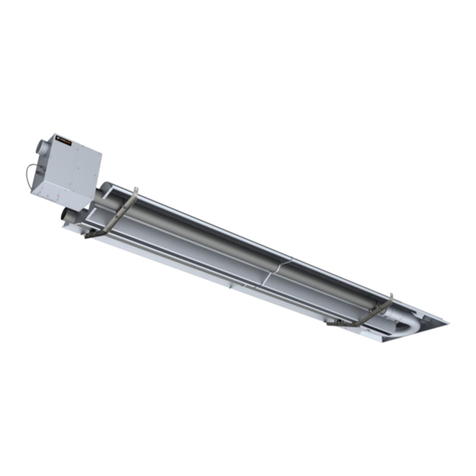
that commitment. Series WTH models are field assembled, low intensity infrared heaters that are easy to install
and maintain, and which were engineered with significant input from our customers. They are designed to provide
economical operation and trouble-free service for years to come.
Important
These instructions, the layout drawing, local codes and ordinances, and applicable standards such as apply to gas
piping and electrical wiring comprise the basic information needed to complete the installation, and must be
thoroughly understood along with general building codes before proceeding.
Only personnel who have been trained and understand all applicable codes should undertake the installation. SRP
Representatives are Factory Certified in the service and application of this equipment and can be called on for
helpful suggestions about installation.
Installation Codes
Installations must comply with local building codes, or in their absence, the latest edition of the national regulations
and procedures as listed below.
General Installation and Gas Codes
Heaters must be installed only for use with the type of gas appearing on the rating plate, and the installation must
conform to the National Fuel Gas Code, ANSI Z223.1/NFPA 54 in the USA and CSA B149.1 and B149.2
Installation Codes in Canada.
This heater maybe approved for either indoor or outdoor installation. Not for use in residential dwellings, refer to
Rating plate.
Aircraft Hangar Installation
Installation in aircraft hangars must conform to the Standard for Aircraft Hangars, ANSI/NFPA 409 in the USA and
CSA B149.1 and B149.2 Installation Codes in Canada.
Public Garage Installation
Installation in public garages must conform to the Standard for Parking Structures, NFPA-88A or Standard for
Repair Garages, NFPA 88B, in the USA and CSA B149.1 and B149.2 Installation Codes in Canada.
Parking Structures
Technical requirements are outlined in ANSI/NFPA 88B (USA)

Series WTH Page 5 LT105 Feb. 2019
Gas Supply Lines
Gas supply pipe sizing must be in accordance with the National Fuel Gas Code, ANSI Z223.1/NFPA 54 in the USA
and CSA B149.1 and B149.2 Installation Codes in Canada.
A 1/8” NPT plugged tap must be installed in the gas line connection immediately upstream of the burner farthest
from the gas supply meter to allow checking of system gas pressure.
Electrical
All heaters must be electrically grounded in accordance with the National Electric Code, ANSI/NFPA 70 in the USA,
and the Canadian Electric Code, CSA C22.1 in Canada, and must comply with all local requirements.
Venting
Refer to the National Fuel Gas Code, ANSI Z223.1/NFPA 54 in the USA and CSA B149.1 and B149.2 Installation
Codes in Canada for proper location, sizing and installation of vents as well as information on clearance
requirements when penetrating combustible walls for venting purposes.
General Specifications
Gas Supply
Inlet Pressure
Natural Gas:
Minimum
Maximum
5.0”W.C.
14.0”W.C.
Propane Gas:
Minimum
Maximum
11.5”W.C.
14.0”W.C.
Manifold Pressure
Natural Gas:
3.5”W.C.
Propane Gas:
10.5”W.C.
Inlet Connection
Natural Gas or Propane: ½” female NPT
Electric Supply
120 VAC, 60 HZ, 1 Amp: 36”cord with grounded 3 prong plug
Flue and Outside Air Connection
4”O.D. male connection for flue adapter and outside air (optional) provided at the heater

Series WTH Page 6 LT105 Feb. 2019
Dimensional Charts
Heat Exchanger
Figure 1: Overall Dimensional Information
Figure 2: Component Dimensional Information

Series WTH Page 7 LT105 Feb. 2019
Configurations
Table 1: Configuration Information
Note:
Baffles are always placed in the last section of radiant tube.
Baffles are either aluminized or stainless steel sections 6' long.
When only 6' is required an aluminized steel baffle is installed, except on the WTH-40,000 where a special 6'
stainless steel baffle with a red identification tab must be installed.
When 12' is required, a 6’ stainless steel baffle is inserted first into the end tube followed by another 6’
aluminized baffle. The stainless steel baffle is now closest to the burner.
Part numbers for reference are:
CT045 Baffle Kit, WTH-40,000 BTU/hr only, 6' long, stainless steel with red identification tab.
CT046 Baffle Kit, 6' long, aluminized steel
CT047 Baffle Kit, 12' long aluminized & stainless steel.
*The following Special Configurations are also approved:
80,000 BTU/Hr, 50’heat exchanger with no baffle or 6’aluminized baffle
100,000 BTU/Hr, 50’ heat exchanger with no baffle or 6’aluminized baffle
150,000 BTU/Hr, 60’heat exchanger with no baffle or 6’aluminized baffle
The following special configurations are also approved with Premium Heat Exchanger only:
80,000 BTU/Hr, 20’heat exchanger with 12’baffle
100,000 BTU/Hr, 20’heat exchanger with 12’baffle
125,000 BTU/Hr, 30’heat exchanger with 12’baffle
205,000 BTU/Hr, 50' heat exchanger with a 4' baffle at 40', and a 8' baffle at 50'.
Model
* Special Configurations
available –see below
Rate
(BTU/Hr)
Heat Exchanger Length ft. (m)
Baffle
ft.(m)
Minimum
Maximum
WTH-40
40,000
10' (3m)
20' (6m)
6' (1.8m)
WTH-60
60,000
20' (6m)
30' (9m)
6' (1.8m)
WTH-80
80,000
30' (9m)
40' (12m)
12' (3.6m)
WTH-100
100,000
30' (9m)
40' (12m)
12' (3.6m)
WTH-125
125,000
40' (12m)
50' (15m)
6' (1.8m)
WTH-150
150,000
40' (12m)
60' (18m)
6' (1.8m)
WTH-175
175,000
50' (15m)
60' (18m)
-
WTH-205
205,000
60' (18m)
70' (21m)
-

Series WTH Page 8 LT105 Feb. 2019
Clearance to Combustibles
A general clearance of 18 (0.5 m) in every direction is recommended for servicing only around each Burner and
air supply (at the far end of each radiant tube). Also, to ensure adequate air flow in and around the Heating System.
In addition to this it is very important to observe the minimum clearance to combustibles at all times to
avoid any possibility of property damage or personal injury.
WARNING
Clearances as marked on the heater body must be maintained from vehicles parked beneath. Signs should be
posted identifying any possible violation of the clearance distances from the heater in all vehicle areas.
Maximum allowable stacking height in storage areas should be identified with signs or appropriate markings
adjacent to the thermostat or in a conspicuous location.
Table 2 lists the minimum clearance to combustible materials for various installation configurations. Note that
standard clearances also apply to installation above T-bar ceilings and above decorative grills. Additional clearance
may be required for glass, painted surfaces and other materials which maybe damaged by radiant or convective
heat.
Combustible materials are considered to be wood, compressed paper, plant fibres, plastics, Plexiglas or other
materials capable of being ignited and burned. Such materials shall be considered combustible even though flame-
proofed, fire-retardant treated or plastered.
Elbows and U-bends are un-heat treated aluminized material and are typically installed without reflectors. Reflector
miter kits are available for U-bends and elbows.
Adequate clearance to sprinkler heads must be maintained.
The stated clearance to combustibles represents a surface temperature of 90°F (50°C) above room temperature.
Building materials with low heat tolerance (i.e. plastics, vinyl siding, canvas, tri-ply, etc.) may be subject to
degradation at lower temperatures. It is the installer’s responsibility to ensure that adjacent materials are
protected from deterioration.
Note 1:
Bottom Shields are approved for all burner sizes. The below clearance (dimension C in Table 2) may be reduced by
25% when an approved Bottom Shield is used.
Note 2:
Reduced clearances downstream from the burner are approved for all configurations. Dimensions B, C, and D in
Table 2 can be reduced for locations 25' (7.6 m) or more downstream from a burner maximum reduction is 50%

Series WTH Page 9 LT105 Feb. 2019
Table 2: Minimum Clearance to Combustibles Inches (cm)
Model No.: WTH
Reflector
Configurations
Dim
In
(cm)
40
MBH
60
MBH
80
MBH
100
MBH
125
MBH
150
MBH
175
MBH
205
MBH
Horizontal
A
B
C
D
2(5)
18(46)
45(114)
18(46)
2(5)
25(63)
58(147)
25(63)
2(5)
26(66)
62(157)
26(66)
2(5)
30(76)
67(170)
30(76)
4(10)
33(84)
71(180)
33(84)
4(10)
36(91)
74(188)
36(91)
6(15)
40(102)
78(198)
40(102)
6(15)
44(46)
80(203)
44(46)
45° Reflector Tilt
A
B
C
D
4(10)
4(10)
40(102)
38(97)
4(10)
4(10)
50(127)
46(117)
4(10)
4(10)
58(147)
50(127)
4(10)
4(10)
67(170)
58(147)
6(15)
4(10)
70(178)
63(160)
6(15)
4(10)
71(180)
64(163)
8(20)
4(10)
74(188)
67(170)
8(20)
4(10)
78(198)
72(183)
One Side Extension
A
B
C
D
2(5)
4(10)
50(127)
35(89)
2(5)
4(10)
58(147)
38(97)
2(5)
4(10)
63(160)
42(107)
2(5)
4(10)
73(185)
45(114)
4(10)
4(10)
76(193)
50(127)
4(10)
4(10)
78(198)
52(132)
6(15)
6(15)
80(203)
54(137)
6(15)
6(15)
84(203)
56(142)

Series WTH Page 10 LT105 Feb. 2019
Model No.: WTH
Reflector
Configurations
Dim
In (cm)
40
MBH
60
MBH
80
MBH
100
MBH
125
MBH
150
MBH
175
MBH
205
MBH
U-Tube, Horizontal
A
B
C
D
-
-
-
-
2(5)
25(64)
59(150)
22(56)
2(5)
28(71)
62(157)
26(66)
2(5)
30(76)
71(180)
30(76)
4(10)
34(86)
74(188)
33(66)
4(10)
37(94)
76(193)
36(84)
6(15)
40(102)
78(198)
40(102)
6(15)
45(114)
82(208)
44(112)
U-Tube, Opposite 45°
A
B
C
D
-
-
-
-
4(10)
46(117)
51(129)
16(41)
4(10)
50(127)
54(137)
18(46)
4(10)
54(137)
64(163)
18(46)
4(10)
63(160)
69(175)
22(56)
4(10)
64(163)
71(180)
24(61)
8(20)
67(170)
74(188)
26(66)
10(25)
72(183)
78(198)
29(74)
Unvented
Above
End
14(30)
26(66)
14(30)
26(66)
18(46)
26(66)
18(46)
26(66)
18(46)
26(66)
18(46)
32(81)
18(46)
32(81)
18(46)
32(81)
Vented
End
18(46)
18(46)
18(46)
18(46)
18(46)
18(46)
18(46)
18(46)
Note: All dimensions shown are measured from outside surface of all tubes, reflectors and fittings

Series WTH Page 11 LT105 Feb. 2019
Installation –Standard Heat Exchanger
Installation Sequence
Generally, there is no unique sequence for installation of the burner or heat exchanger. A review of the job site will
usually indicate a logical installation order. However, time and expense can be saved if installation is begun at the
most critical dimension, watching for interference from overhead doors, cranes, auto lifts etc.
Figure 3 provides a general overview of the components utilized in the installation for the Heater Exchanger Model
Figure 3: General Overview of Installation for Standard Heat Exchanger
A general ordered sequence for installation is provided below for reference.
HANGERS INSTALLATION
Suspension mechanism must allow for lateral tubing expansion. A minimum 12" length welded link chain with a
working load limit of at least 200 lbs. is recommended (refer to Figure 4 for more details). SRP recommends
and make available “quick links” for connecting chain. If any open ended turnbuckles are used, the open ends
must be closed to avoid unhooking chain with inadvertent contact.
Locate hanging chain at predetermined suspension points in the structure. It is required that the first 2 hangers
be about 8' to 9' away. Thereafter, 10' apart on average is acceptable for the remainder of the heat exchanger.
At no time should hangers be more than 12' apart, (see Figure 5).

Series WTH Page 12 LT105 Feb. 2019
Figure 4: Suspension Mechanism
Install the tube and reflector support hanger on the chain with Quick Links or ‘S’ hooks refer to Figure 4 &
Figure 5
Figure 5: Typical Hanging Points
Place the first (flanged, aluminized) tube in the first two hangers (Figure 6). Be sure the flange is toward the
intended burner location. The other end of the tube should have the first coupling already loosely fitted.

Series WTH Page 13 LT105 Feb. 2019
TUBE INSTALLATION
Always use all the hangers supplied. The combustion tube (first tube) utilizes the flange plus one hanger for
support and thereafter 1 hanger section. The reflector brace should be installed 6” – 12” from burner. Also the
tube weld seam must face down, refer to Figure 6 for more details.
Figure 6: Installation of First section of Flanged Tube
For all remaining tubes, fit the end of the tube with a coupling refer to Figure 7, (the coupling should be loose).

Series WTH Page 14 LT105 Feb. 2019
Figure 7: Installation of Heat Exchanger Tube and Coupling
Note: For all coupling joints, ensure that the tube joint is in the center of the coupling length, and that the
overlap joint of the coupling is above the centerline of the tube. Also ensure that the weld seam on ALL tubes is
facing down.
Note: In order to obtain smoothly sealed coupling liners, tighten each of the coupling bands progressively and
alternately. Tightening one band completely before the other may result in an undesirable wrinkle in the liner
(refer to Figure 8). Be sure not to over torque the coupling. (Torque coupling to 15-25 lbf-ft).
Figure 8: “J” Bolt and Coupling Installations
Continue placing tubes, couplings and reflectors to complete the heater assembly. Ensure heat exchanger
sections line up straight. Couplings should be tightened as heat exchanger is placed, since it is more difficult to
do so once the reflector is in position.

Series WTH Page 15 LT105 Feb. 2019
HEATER AND BAFFLE INSTALLATION
Locate the burner gasket provided, bolt the burner in place on the tube flange with provided hardware. Burner
must never be installed in a tilted position. The sense electrode of the burner cup should be in the 12
o’clock position (Figure 9)
Figure 9: Burner Gasket Installation
If required for your heater model (refer to Table 1), install the baffle at the end of the heat exchanger. The
small tab on the baffle is folded over the end of the tube and clamped in place by the vent connector and vent
system, refer to Figure 10.
Note: Baffles are always placed at the end of the last heat exchanger tube length, with the exception of the
special configuration for 205,000 BTU/hr with a 50' tube lengt. Refer to Figure 3 for more details.
Note: Baffles are either one or two sections (each section is 6' in length). Multiple sections are simply
clipped together. Where stainless and aluminized sections are supplied, always place the stainless steel
section closest to the burner. The easiest installation method is to pull the baffle through the tube using a long
wire.

Series WTH Page 16 LT105 Feb. 2019
Figure 10: Baffle Installation
A general overall view of the tubes and reflector hangers are shown in Figure 11 below
Figure 11: Overall view of Tubes and Reflector Hangers

Series WTH Page 17 LT105 Feb. 2019
REFLECTOR INSTALLATION
Slide a reflector section into place within the support hanger, (Figure 12).
Figure 12: Reflector Installation
Install reflector support brackets, one at each reflector overlap position, and one in the middle of each 10'
reflector length. Figure 13 shows the installation of the reflector support bracket.
Figure 13: Reflector Support Bracket Installation
Note: Reflectors should overlap adjacent reflectors minimum 4". Be sure not to tile reflector sections; that is,
reflector sections must be either above both adjacent reflector sections, or below both adjacent reflector sections.
Refer to Figure 14.

Series WTH Page 18 LT105 Feb. 2019
Figure 14: Reflector Overlap Illustration
Secure every second reflector overlap together with a minimum of 2 - #8 x 3/8" long screws (not supplied), and
secure reflector to the reflector bracket at this point by tightening down #8 x 1¼" screws supplied with reflector
brackets (Figure 15). The remaining reflector overlap joints and reflector brackets are left loose to
accommodate system movement.
Figure 15: Reflector Supports Installation and Reflector Overlap

Series WTH Page 19 LT105 Feb. 2019
Install End Cap as shown in Figure 4 and Figure 16
Figure 16: Reflector End Cap Installation

Series WTH Page 20 LT105 Feb. 2019
ELBOW AND “U-TUBE” INSTALLATION
If required by the heater layout, install 90° elbows or U-tube where indicated. Refer to Figure 17 for details.
Note: Elbows or U-tubes are typically installed without reflectors. To reduce the above clearance to
combustibles distance use miter reflectors (see Figure 18) and refer to Clearance to Combustibles information.
Figure 17: 90° Elbow and U-Tube Assembly Detail
Elbows or U Tubes must be located not less than 10 feet from the burner on model WTH-80 and smaller, not
less than 15 feet from the burner on WTH-100 to WTH-150, and not less than 20 feet from the burner on WTH-
175 and not less than 30 ft. on model WTH-205.
This manual suits for next models
8
Table of contents
Other SRP Heater manuals
Popular Heater manuals by other brands
Olimpia splendid
Olimpia splendid Caldostile M Instructions for installation, use and maintenance
Trebs
Trebs 99405 manual
Mi-T-M
Mi-T-M MH-0042-PM10 Operator's manual
Hayward
Hayward C-SPA-XI 5.5 Installation and operation manual
Webber
Webber R 257 TC datasheet
Dimplex
Dimplex AF12 Series installation instructions
