Sodi Sigma KZ User manual

This document can not be reproduced or released without the Sodikart authorization.
Congure the kart according to the guide instructions.
Use spare parts of Sodi origin.
MAN.SIG.EN.02

This document can not be reproduced or released without the Sodikart authorization.
MAN.SIG.EN.02
04/2014
2CONFIGURE THE KART ACCORDING TO THE GUIDE INSTRUCTIONS
User maintenance guide
You have decided to acquire a SODI chassis. We would like to thank you for
your trust (in us).
Your kart has been developed for performance and safety.
It is the outcome of SODIKART’s experience and of the latest research at the
highest level of competition.
This manual contains instructions for the assembly and the maintenance of
your kart, according to the rules of the art.
Safety on a track is a personal and collective matter at the same time: taking
care of your kart is the rst guarantee of your safety and of the safety of other
pilots.
This manual also contains advice about adjustments.
Their purpose is to help you exploiting all the potential of your kart.
Enjoy driving your kart,

This document can not be reproduced or released without the Sodikart authorization.
MAN.SIG.EN.02
04/2014 3
USE SPARE PARTS OF SODI ORIGIN
User maintenance guide
Table of contents
1 - Safety instructions ............................4
1.1 - Recap of all warnings included in this
manual ........................................................ 5
2 - Reception ...........................................6
2.1 - Tooling for assembly and adjustment .......... 7
2.2 - Maintenance products .................................. 7
3 - Assembly ...........................................8
3.1 - Precautions and recommendations .............. 8
3.2 - Assembly of the steering column and
steering wheel ............................................. 8
3.3 - Positioning of the safety brake cable.......... 10
3.4 - Frame stabilizers ........................................ 10
3.5 - Assembly of the fuel tank and of the
overow bottle ........................................... 10
3.6 - Assembly of the seat .................................. 11
3.7 - Assembly of the seat stiffeners ................... 12
3.8 - Assembly of the bodywork.......................... 13
3.9 - Mounting the rear protections..................... 15
3.10 - Mounting the rear protections DD2 .......... 15
3.11 - Mounting the front brake hose (optional) .. 16
4 - Commissioning ...............................17
4.1 - Safety instructions to the pilots................... 17
4.2 - Pilot protection............................................ 17
5 - Adjustments .....................................18
5.1 - Standard adjustments ................................ 18
5.2 - Adjustment of front wheels ......................... 20
5.2.1 - Adjustment of front tracking width .......... 20
5.2.2 - Adjustment of front wheel height ............ 20
5.2.3 - Adjustment of the caster ......................... 21
5.2.4 - Adjustment of the camber ...................... 22
5.2.5 - Front wheel alignment ............................ 23
5.2.6 - Adjustment of tie rods ............................. 23
5.3 - Adjustment of rear wheels .......................... 24
5.3.1 - Adjustment of hubs ................................. 24
5.3.2 - Position of rear axle ............................... 24
5.3.3 - Type of axle ............................................ 24
5.4 - Adjustment of seat ...................................... 25
5.5 - Adjustment of the brake distributor ............. 25
5.5.1 - Standard adjustment .............................. 25
5.5.2 - More braking power on the front brakes 25
5.5.3 - More braking power on the rear brakes . 25
6 - Maintenance.....................................26
6.1 - Brakes ........................................................ 26
6.1.1 - Fluids and lubricants .............................. 26
6.1.2 - Frequency of cleaning and maintenance 26
6.1.3 - Replacing brake pads on the D18
4-piston calipers (front) .......................... 27
6.1.4 - Replacing brake pads on the D24
4-piston calipers (rear) ........................... 27
6.1.5 - Adjusting the gap between the pads
and the disc ............................................ 28
6.1.6 - Replacing the brake hose ...................... 28
6.1.7 - Bleeding the front brake circuit............... 28
6.1.8 - Bleeding the rear brake circuit ............... 30
6.1.9 - Bleeding the steering wheel
controlled front brake circuit ................... 31
6.1.10 - Replacing rear calliper seals / 4
piston caliper pistons D18 (front) ........... 32
6.1.11 - Replacing rear calliper seals / 4
piston caliper pistons D24 (rear) ............ 33
6.1.12 - Replacing master cylinder seals
and pistons ............................................. 35
6.1.13 - Replacing the front master cylinder
pistons .................................................... 37
6.1.14 - Cleaning ............................................... 37
6.2 - Tyres ........................................................... 38
6.2.1 - Tyres change .......................................... 38
6.2.2 - Table of the recommended tyre
pressures ............................................... 39
6.3 - Cleaning the chassis .................................. 40
6.4 - Maintenance summary ............................... 40
6.4.1 - Bolting .................................................... 40
6.4.2 - Steering .................................................. 40
6.4.3 - Bodywork parts ...................................... 40
6.4.4 - Tyres ...................................................... 40
6.4.5 - Braking ................................................... 40
7 - Trouble shooting .............................41
7.1 - The kart will not brake ................................ 41
7.2 - The kart brakes continually ........................ 41
7.3 - The kart is hard to turn ............................... 41
7.4 - The steering of the kart is not precise ........ 41
7.5 - The kart tends to go to the side .................. 41
7.6 - The kart skids very much on bends ............ 41
8 - Index .................................................42
9 - Homologation ..................................45
9.1 - SIGMA S3................................................... 45
9.2 - SIGMA KZ .................................................. 46
9.3 - SIGMA DD2 ................................................ 47

This document can not be reproduced or released without the Sodikart authorization.
MAN.SIG.EN.02
04/2014
4CONFIGURE THE KART ACCORDING TO THE GUIDE INSTRUCTIONS
User maintenance guide
This user guide is updated by SODIKART to
allow, without delay, to know the last safety
and maintenance improvements.
Refer to our website regularly, to download
the last version of user guide.
This document is a translation of the French manual,
Document MAN.SIG.CEL.FR.01 (original version),
which will prevail in the event of a dispute.
The illustrations are non-contractual.
© Sodikart 2014 .
1 - Safety instructions
The kart has been designed in accordance with the
pending rules of the CIK / FIA in force, which ensures
an optimum safety in normal conditions of use.
Its high speed and performances imply a proper
maintenance.
For your safety and the one of other pilots, please
thoroughly respect:
● The assembly instructions.
● The adjustment recommendations.
● The maintenance plan.
Please pay especial attention to the instructions or
comments to the following symbols below:
● Gives useful information.
●●Indicates●a●risk●of●property●damage●if●
instructions●are●not●followed.
► Indicates a strong possibility of serious
personnal injury or death if instructions
are not followed.
If you have problems or questions
about your kart, please contact our local
distributor or representative of SODIKART.
Parc d’activités des Hauts de Couëron
B.P.60 - 44220 COUËRON - France
Tel. : (33) 02 40 38 26 20
Fax : (33) 02 40 38 26 21
www.sodikart.com - [email protected]
► The SODI chassis is designed for safety
and reliability in normal conditions
of use. Before using it, please read
this manual and carefully follow the
instructions. By not doing so, you might
be exposed to a risk of severe, even
fatal injury, and your kart might suffer
damages.
► The SODI chassis can only be used on
an approved track and by a driver who
is in possession of a valid membership
card of the kart’s federation of his own
country.
► Prior to going on the track, please check
all points related to safety.
► In order to avoid re, put the kart at
least one meter away from the buildings.
Never leave inammable objects close
to the kart.
► If fuel has been poured, wipe and wait
for vapours to dissipate, before starting
the kart.
► Kids and domestic animals have to be
kept away from the kart and the track.
► Never drive the kart without adequate
pilot equipment.

This document can not be reproduced or released without the Sodikart authorization.
MAN.SIG.EN.02
04/2014 5
USE SPARE PARTS OF SODI ORIGIN
User maintenance guide
1.1 - Recap of all warnings included in this
manual
Chapter: Assembly
►A bad assembly or a bad adjustment of the steering
system can lead to accidents. Systematically
check the tightening of the system and its
adjustment./ Page 9
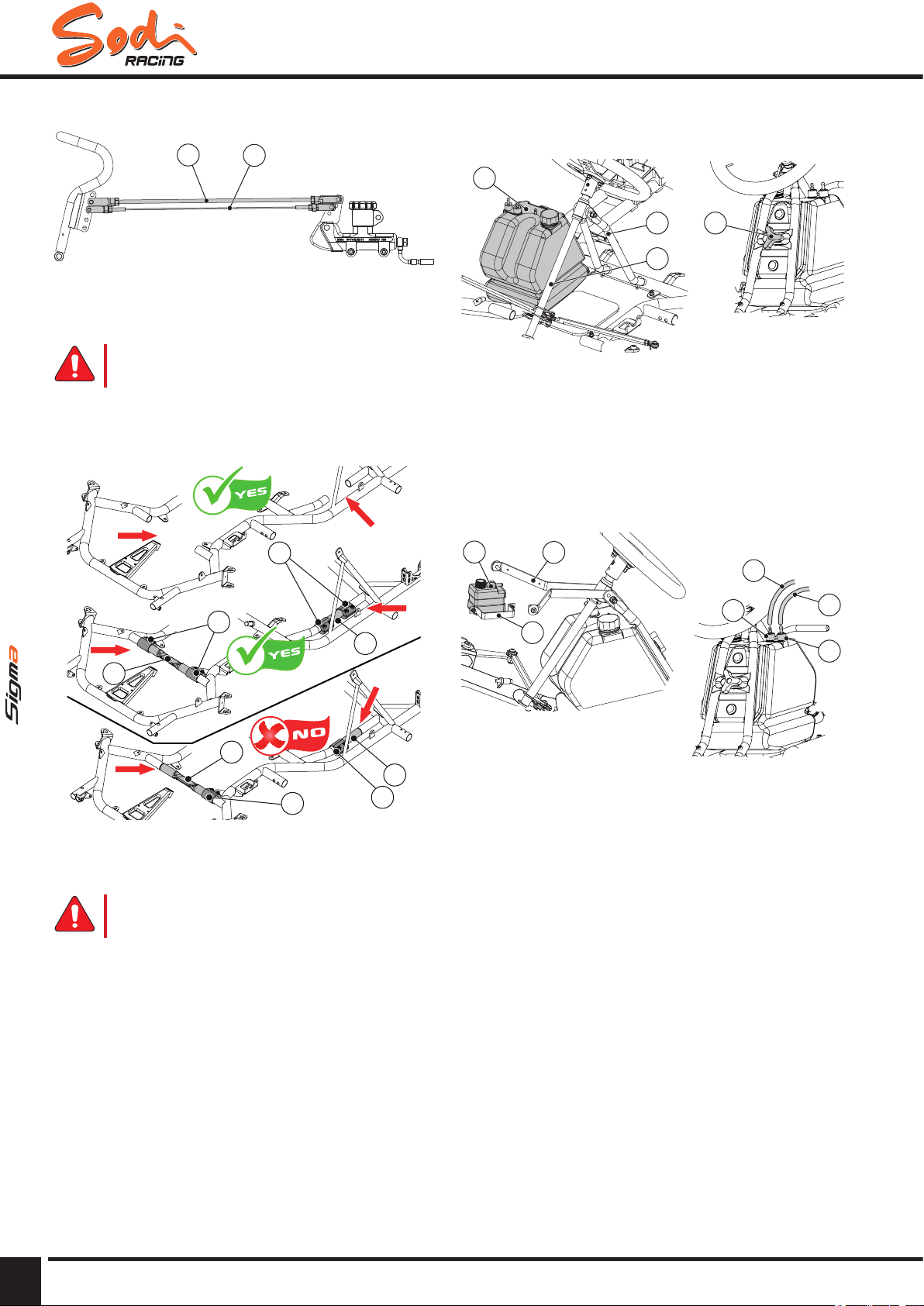
►Always t the safety cable clips (1) under the staples
of the brake rod (2)./ Page 10
►Always attach the stabilisers to the frame with a
sleeve at each side./ Page 10
Chapter: Commissioning
►Your kart can only be driven on a track approved by
CIK/FIA, or your local federation and by a driver who
is in possession of a valid membership card of the
kart’s federation of his own country./ Page 17
►For your safety and the safety of other pilots, strictly
follow the above instructions: not doing so may lead
to severe, even fatal injuries./ Page 17
Chapter: Adjustments
►Never drive with badly tightened wheels: it may lead
to severe, even fatal injuries./ Page 23
►Make sure that each ball joint penetrates at least 5
threads in the tie rods./ Page 23
►Badly tightened wheels may lead to severe, even
fatal injuries./ Page 24
►Check the hub key (5) is correctly
positioned./ Page 24
►Never position the hubs beyond the maximum
allowed width: it may lead to severe or even fatal
injuries./ Page 24
►The brake system is a key safety item of the kart.
Regularly check all its components./ Page 25
►In case of doubt, do not drive before xing the
problem./ Page 25
►Bad maintenance of the brakes can lead to severe,
even fatal injuries./ Page 25
►Never repair a break system on your own; return it
to your local dealer./ Page 25
Chapter: Maintenance
►The Super Blue brake uid has been designed for
racing use and is used exclusively for this purpose
(forbidden on open road)./ Page 26
►Use brake uid DOT4 only. Using another brake
uid could cause leaks and failure of the brake
system./ Page 26
►Check the pads for wear before every start-
up./ Page 27
►Never drive with excessively worn pads (minimum
thickness for the D18 4-piston calipers (front):
4mm)./ Page 27
►The brake is an essential safety element. If the
braking system is defective or you have the slightest
doubt, do not put the kart in service./ Page 27
►Never drive with excessively worn pads (minimum
thickness of pads for D24 4-piston calipers (rear): 6
mm)./ Page 27
►The brake is an essential safety element. Do not put
the kart in operation if the break system is faulty or if
you have a doubt./ Page 28
►Faulty braking system may lead to a serious or even
fatal injury./ Page 28
►Check connexions of hoses, no leak./ Page 28
►Use brake uid DOT 4 only./ Page 28
►An air bubble in the brake system can lead to a
partial or total lost of brakes and may lead to a
serious or even fatal injury./ Page 29
►Leaks in the brake system may lead to a serious or
even fatal injury./ Page 29
►Moisture in the brake uid may cause vapour lock
and a sudden loss of braking power, may lead to a
serious or even fatal injury./ Page 29
►Use brake uid DOT 4 only/ Page 29
►Test the brake after each bleed./ Page 29
►Do not use any cleaning product that could damage
the seals. A brake uid leak could appear, causing a
serious or fatal accident./ Page 33
►If WD-40 or a similar cleaning product is splashed
on the brake disc or calliper, braking will be less
efcient or possibly totally ineffective for a few
revolutions. This could cause a serious or fatal
accident./ Page 37
►Do not apply WD-40 or other cleaning products to
the brake pump./ Page 37
►Change all damaged rims. A damaged rim may lead
to a loss of tyre or loss of pressure and may lead to
a serious or even fatal injury./ Page 38
►Check the tyre wear daily. Worn or damaged tyres
may lead to a serious or even fatal injury./ Page 38
►Never run with worn or damaged tyres: a burst
of tyre may lead to a serious or even fatal
injury./ Page 38
►Always blow up tyre with the pressure
recommended by the manufacturer./ Page 38
►Cold tyres have a reduced adherence, and increase
the loss of control of the kart. This may lead to a
serious or even fatal injury./ Page 38
►Too much grip reduces the stability of the kart under
impact, and lead to a tendency to go on two wheels.
It also increases the risk of riding over./ Page 38
►Store tyres in an appropriate area to prevent re
hazard./ Page 38
►Never inate above 4 bars: there is a risk of severe
injury due to potential failure of the rim. / Page 38
►Spray cleaning product on brake pads or brake
caliper may reduce the braking ability partially or
totally, and can lead to a serious accident./ Page 40

This document can not be reproduced or released without the Sodikart authorization.
MAN.SIG.EN.02
04/2014
6CONFIGURE THE KART ACCORDING TO THE GUIDE INSTRUCTIONS
User maintenance guide
2 - Reception
5
6
12
13
14
15
8
9
10
3
7
2
11
1
4
15
Legend
1 Spoiler
2 Nassau panel
3 Steering column assembly
4 Steering wheel
5 Frame
6 Overow bottle
7 Left side pod
8 Left side pod support
9 Right side pod
10 Right side pod support
11 Gear lever assembly (KZ only)
12 Rear bumper
13 Fuel tank
14 Seat
15 Rim
●●Prior●to●assembling●your●kart,●check●the●
above●described●elements●and●familiarize●
yourself●with●them.
● For part numbers, refer to the exploded
view.

This document can not be reproduced or released without the Sodikart authorization.
MAN.SIG.EN.02
04/2014 7
USE SPARE PARTS OF SODI ORIGIN
User maintenance guide
2.1 - Tooling for assembly and adjustment
2
1
5
7
7
7
4
6 9
8
3
Designation Ø Part No.
1 Stub axle spacer adjuster
(Hub) (*)
- OU931.007
2 Stub axle screw adjuster
(Stub axle) (*)
- OU931.006
3 Key for slotted round nut (*) M20 OU914.003
4 T handle wrench Allen key 3 OU911.001
4 T handle wrench Allen key 4 OU911.002
4 T handle wrench Allen key 5 OU911.003
4 T handle wrench Allen key 6 OU911.004
4 T handle wrench Allen key 8 OU911.005
5 T handle socket spanner 8 OU912.004
5 T handle socket spanner 10 OU912.001
5 T handle socket spanner 11 OU912.002
5 T handle socket spanner 13 OU912.003
6 Piston stop centring device - OU951.004
7 Master cylinder tool kit - OU951.003
8 Brake bleeder - OU951.002
9 Special glue - LU861.001
● (*) Supplied with the chassis.
2.2 - Maintenance products
Designation Part No.
Cleaner : (paint - plastics) LU834.003
WD 40 LU833.003
Grease (for chain) LU825.005
● For other tools, accessories and
equipment, visit ITAKA website.

This document can not be reproduced or released without the Sodikart authorization.
MAN.SIG.EN.02
04/2014
8CONFIGURE THE KART ACCORDING TO THE GUIDE INSTRUCTIONS
User maintenance guide
3 - Assembly
3.1 - Precautions and recommendations
●●Do●not●overtighten●screws●and●bolts.
● Tightening torque Ø 6 = 10 to 12 mN.
● Tightening torque Ø 8 = 12 to 23 mN.
● Tightening torque Ø 10 = 23 to 47 mN.
● Tightening torques for rims on hub : 25 mN.
● Screws without bolts: 1 drop of special glue
(LU861.001).
● Lubricate rotating parts, ball joints, gas cable ...
3.2 - Assembly of the steering column and
steering wheel
3
6
4
7
5
2
6
8
1
Legend
1 Plastic steering column support
2 Steering wheel support
3 Nassau panel support
4 Steering column
5 Steering column support
6 Steering tie rods + Ball joints
7 Clutch handle (KZ only)
8 Gearbox control lever (KZ only)
● Raise the set as in picture.
Step 1
2
2
1
1
Legend
1 Pin canon
2 Screw + nut
● Place the steering column support on the two pins
canons (1).
● Put the screws + nuts (2) as indicated in picture.
● Tighten the assembly.
Step 2
2
1
3
Legend
1 Ball joint
2 Nut
3 Split pin
● Insert the threaded end of the steering column in the
ball joint (1).
● Tighten the nut (2).
● Tighten the assembly.
● Put the split pin (3) into the hole of steering column.

This document can not be reproduced or released without the Sodikart authorization.
MAN.SIG.EN.02
04/2014 9
USE SPARE PARTS OF SODI ORIGIN
User maintenance guide
Step 3
1
Legend
1 Screw + nut
● Tighten the nut (1).
● Tighten the assembly.
Step 4
21
Legend
1 Ball joint
2 Stub axle arm
● Cut the tie-wrap maintaining the stub axles.
● Place the ball joints (1) above the stub axle arm (2).
● Insert the screw into the stub axle arm.
● Place the washer between the ball joint (1) and the
stub axle arm (2).
● Tighten the nut.
● Tighten the assembly.
Step 5
1
4
3
2
Legend
1 Support
2 Screw
3 Top of the wheel
4 Steering column
● Tighten the steering wheel (straight side up (3)) with
the 3 screws (2) on the steering wheel support (1).
● Tighten the steering wheel support (1) on the
steering column (4).
●●Once●the●steering●system●is●assembled,●
please●check●that●the●steering●wheel●is●free●
to●make●a●quarter●of●a●turn●right●and●left.
► A bad assembly or a bad adjustment
of the steering system can lead to
accidents. Systematically check
the tightening of the system and its
adjustment.

This document can not be reproduced or released without the Sodikart authorization.
MAN.SIG.EN.02
04/2014
10 CONFIGURE THE KART ACCORDING TO THE GUIDE INSTRUCTIONS
User maintenance guide
3.3 - Positioning of the safety brake cable
1
2
Legend
1 Safety cable
2 Brake rod
► Always t the safety cable clips (1)
under the staples of the brake rod (2).
3.4 - Frame stabilizers
1
1
1
1
2
2
2
2
Legend
1 Frame stabilizer
2 Stabilizer sleeve
► Always attach the stabilisers to the
frame with a sleeve at each side.
3.5 - Assembly of the fuel tank and of the
overow bottle
3
2 4
1
Legend
1 Fuel tank
2 Steering column support
3 Steering column
4 Fly nut
● Insert the fuel tank (1) between the steering column
support (2) and the steering column (3).
● Tighten the fuel tank (1) with the y nut (4).
7
9
8
10
11
56
Legend
5 Overow bottle
6 Nassau panel support
7 Overow bottle support
8 Overow bottle hose
9 Return
10 Petrol tank hose
11 Red plug
● Put the overow bottle (5) on the nassau panel
support (6) with the overow bottle support (7).
● Connect the overow bottle hose (8) ) to the return
(9).
● Connect the petrol tank hose (10) to the red plug
(11).

This document can not be reproduced or released without the Sodikart authorization.
MAN.SIG.EN.02
04/2014 11
USE SPARE PARTS OF SODI ORIGIN
User maintenance guide
Ground clearance
A
1
2
Legend
1 Seat
2 Frame tubes
● Adjust the bottom of the seat (1) with the lower face
of the frame tubes (2).
Seat Position
C
B
SIGMA S3
● B = 220 mm ± 5 mm (mid-point of the rounded,
middle of the seat).
● C = 1020 mm ± 10 mm.
SIGMA KZ
● B = 210 mm ± 5 mm (mid-point of the rounded,
middle of the seat).
● C = 1050 mm ± 10 mm.
SIGMA DD2
● B = 210 mm ± 5 mm (mid-point of the rounded,
middle of the seat).
● C = 1040 mm ± 10 mm.
●●Check●the●presence●of●the●diver●under●the●
red●plug.
3.6 - Assembly of the seat
1
1
2
2
1
1
Legend
1 Fixing points
2 Seat supports
● Measurements given below correspond
to the standard adjustment of the seat,
recommended by SODIKART, for your
chassis.
● Get the seat supports (2) closer, or wider, depending
on the seat size.
● Use the shims of the seat xing kit to get a good t.
●●The●washers●of●the●seat●xing●kit●comply●
with●CIK/FIA●and●with●your●local●national●
rules.●

This document can not be reproduced or released without the Sodikart authorization.
MAN.SIG.EN.02
04/2014
12 CONFIGURE THE KART ACCORDING TO THE GUIDE INSTRUCTIONS
User maintenance guide
3.7 - Assembly of the seat stiffeners
Lower end
1
2
Legend
1 Seat stiffener
2 Screw
● Put the seat stiffener lower end (1) in place.
● Pre-tighten the assembly with the screw (2).
● For screws and nuts references, refer to
the spare parts.
Upper end
1
2
Legend
1 Seat stiffener
2 Screw + conical washer + nut
● Place the upper end of the stiffener.
● Make sure there is no contact with the exhaust
system and with any part of the engine.
If necessary, slightly bend the stiffener.
● Drill a 8.5 mm diameter hole in the seat.
● Place one screw + conical washer (2).
● Tighten both upper and lower end.
● Apply the same procedure to mount the stiffener on
the left side of the seat.
Note: It is possible to install several seat stiffener (left
and right):
- SIGMA S3-SIGMA KZ-SIGMA DD2 :
2 stiffeners left side and 1 right side stiffener.
● For screws and nuts references, refer to
the spare parts.
● For other types of stiffeners, refer to the
spare parts and the website ITAKA.

This document can not be reproduced or released without the Sodikart authorization.
MAN.SIG.EN.02
04/2014 13
USE SPARE PARTS OF SODI ORIGIN
User maintenance guide
3.8 - Assembly of the bodywork
Step 1
1
2
3
4
5
Legend
1 Side pod
2 Side pod support
3 Screw
4 Washer
5 Nut
● Place the side pod (1) on the side pod support (2).
● Place the screws (3) through the side pod (1) and
the side pod support (2).
● Tighten the assembly using the nuts (5). Remember
to include the washers (4).
● For screws and nuts references, refer to
the spare parts.
Step 2
1
3
2
2
3
Legend
1 Bushing
2 Screw
3 Nut
● Insert the bushings (1) in the nozzles on the frame.
● Insert the assembly into the bushings (1).
● Drill the bushings (1) using the holes as a guide and
tighten the assembly with the screws (2) and nuts
(3).
● For screws and nuts references, refer to
the spare parts.
Step 3
1
2
3
4
4
3
Legend
1 Spoiler lower support
2 Front cross member
3 Screw
4 Nut
● Insert the spoiler lower support (1) into the front
cross member of the frame (2).
● Tighten with the screws (3) and the nuts (4).
● For screws and nuts references, refer to
the spare parts.
Step 4
1
2
3
4
4
3
Legend
1 Spoiler upper support
2 Lug
3 Screw
4 Nut
● Place the spoiler upper support (1) on the outer face
of the lug (2).
● Tighten with the screws (3) and the nuts (4).
● For screws and nuts references, refer to
the spare parts.

This document can not be reproduced or released without the Sodikart authorization.
MAN.SIG.EN.02
04/2014
14 CONFIGURE THE KART ACCORDING TO THE GUIDE INSTRUCTIONS
User maintenance guide
Step 5
1
2
2
3
Legend
1 Spoiler
2 Fixing plate
3 Screw
● Assemble the fixing plates (2) on the spoiler (1)
using screws (3).
Step 6
2
1
3
1
5
4
Legend
1 Mounting ange spoiler
2 Upper support
3 Lower support
4 Screw
5 Nut
● Assemble the mounting flange spoiler (1) between
the spoiler upper support (2) and the spoiler lower
support (3) with two screws and two nuts.
6
6
3
2
Legend
2 Upper support
3 Lower support
6 Staple
● Place the staples (6) between the spoiler fixations
(2) and (3).
● Tighten the assembly.
● For screws and nuts references, refer to
the spare parts.
Step 7
2
13
Legend
1 Nasseau panel
2 Lower support
3 Upper support
● Tighten the nasseau panel (1) on its supports (2)
and (3) with screws, nuts, and washers.
● For screws and nuts references, refer to
the spare parts.

This document can not be reproduced or released without the Sodikart authorization.
MAN.SIG.EN.02
04/2014 15
USE SPARE PARTS OF SODI ORIGIN
User maintenance guide
3.9 - Mounting the rear protections
5
3
1
1
4
2
Legend
1 Mounting kit
2 Bumper support
3 Tube chassis
4 Safety lug
5 Chassis lug
● Assemble the mounting kit (1) with the element of
the bumper support (2).
● Mount the assembly in the tube chassis (3), tighten
with the screw of the fixing kit (1).
● Fix the safety lug (4) on the chassis lug (5).
● Apply the same procedure for the other side.
6
7
9
9
9
9
8
8
8
6
8
Legend
6 Bumper support
7 Bumper
8 Screw + nut
9 Screw + nut
● Assemble bumper support (6) on the bumper (7)
using screws and nuts (8).
● Assemble the bumper (7) on the chassis with
screws and nuts (9).
3.10 - Mounting the rear protections DD2
2
2
5
1
3
3
4
4
Legend
1 Tire protection
2 Rear protection
3 Screw + nut
4 Screw + nut
5 Tube protection
● Assemble the tire protection (1) on the rear cover
(2), tighten using the screws and nuts (3).
● Assemble the rear protections (2) per pair and
tighten using the screws and nuts (4).
● Assemble the rear protections (2) with the 2
protection tubes (5).
8
8
7
10
9
10
9
Legend
7 Rear protection
8 Tubes chassis
9 Washer
10 Screw
● Place the rear protection (7) on the chassis tubes
(8).
● Place the washers (9) and tighten using the screws
(10).

This document can not be reproduced or released without the Sodikart authorization.
MAN.SIG.EN.02
04/2014
16 CONFIGURE THE KART ACCORDING TO THE GUIDE INSTRUCTIONS
User maintenance guide
3.11 - Mounting the front brake hose
(optional)
1
2
2
2
3
3
4
Legend
1 Brake hose
2 Landmark drilling
3 Screw + nut
4 Screw + nut
● Drill the alu board to 6 mm on the landmark (2).
● Place the clamps on the brake hose (1) and tighten
the screws and nuts (3).
● Tighten the connection of the brake hose (1) with
the screw and the nut (4).
● To adjust the front tracking width see
Standard adjustments / Front tracking width
(Kart with front brake).

This document can not be reproduced or released without the Sodikart authorization.
MAN.SIG.EN.02
04/2014 17
USE SPARE PARTS OF SODI ORIGIN
User maintenance guide
4 - Commissioning
4.1 - Safety instructions to the pilots
WARNING
► Your kart can only be driven on a track
approved by CIK/FIA, or your local
federation and by a driver who is in
possession of a valid membership
card of the kart’s federation of his own
country.
4.2 - Pilot protection
Before going on the track, the pilot must wear the
following protections:
● Integral helmet: CIK/FIA approved, tting the pilot
head size, with tightened strap and closed visor.
Refer to CIK/FIA regulations (Compulsory).
● Suit: CIK / FIA level 1 or level 2 approved
(Compulsory).
● Gloves (Compulsory).
● Neck protection : CIK/FIA approved (Compulsory).
● Rib protection: tting pilot’s size and seat
(Recommended).
● Rain suit: with water tight fasteners (Recommended
when necessary).
●●Choose●those●equipments●within●the●CIK●/●
FIA●approved●ones●of●the●ITAKA●website.
Driving is forbidden to any pilot:
● Wearing a scarf because of risk with rotating parts.
● With long hair coming out of the helmet.
● With wide oating clothes.
● With health problems, not compatible with high
speed driving.
● Under the inuence of drugs and (or) alcohol.
► For your safety and the safety of
other pilots, strictly follow the above
instructions: not doing so may lead to
severe, even fatal injuries.

This document can not be reproduced or released without the Sodikart authorization.
MAN.SIG.EN.02
04/2014
18 CONFIGURE THE KART ACCORDING TO THE GUIDE INSTRUCTIONS
User maintenance guide
5 - Adjustments
5.1 - Standard adjustments
Dry track Wet track
Stub axle height
SIGMA S3
SIGMA DD2
4mm
4mm + 2mm 2mm
4mm + 4mm
Stub axle height
SIGMA KZ
4mm
4mm + 2mm
0mm
4mm + 4mm + 2mm
Front tracking width
B A
A = 1 rings inside (5mm)
B = 100mm
B A
A = 6 rings inside (30mm)
B = 100mm
Front tracking width
(Kart with front brake)
B
A
A = 1 rings inside (5mm).
B = 100mm
B
A
A = 4 rings inside (20mm).
B = 100mm
Rear tracking width
1390
to
1400
1360
to
1380
Rear axle position MEDIUM MEDIUM

This document can not be reproduced or released without the Sodikart authorization.
MAN.SIG.EN.02
04/2014 19
USE SPARE PARTS OF SODI ORIGIN
User maintenance guide
Dry track Wet track
Position of eccentrics
TOP
FWD
Mark - Forward
Eccentric 1°
Mark – Backward
BOTTOM
TOP
FWD
Mark - Forward
Eccentric 1°
Mark – Backward
BOTTOM
Position of steering tie rods
ends
1
B
A
2 1
A
B
B-1 or A-1
1
A
2 1
A
B
A-1
Lateral stabilizer
SIGMA S3
SIGMA DD2
REMOVE the stabilizer. REMOVE or PLACE the stabilizer
following track conditions.
Lateral stabilizer
SIGMA KZ REMOVE the stabilizer. REMOVE or PLACE the stabilizer
following track conditions.
Front stabilizer REMOVE or PLACE the stabilizer
following track conditions.
REMOVE or PLACE the stabilizer
following track conditions.
Tyres (Cf. chap. 6.2.2) (Cf. chap. 6.2.2)
Seat stiffeners SIGMA S3 - SIGMA DD2 :
- 2 on the left and 1 on the right.
SIGMA KZ :
- 2 on the left and 1 on the right.
SIGMA S3 - SIGMA DD2 :
- 2 on the left and 1 on the right.
SIGMA KZ :
- 2 on the left and 2 on the right.
● These adjustments are given for
information. It is advisable to rene these
adjustments according to track conditions
(weather - grip), driving, engine and tires.
●●Always●attach●the●stabilisers●to●the●frame●
with●a●sleeve●at●each●side.

This document can not be reproduced or released without the Sodikart authorization.
MAN.SIG.EN.02
04/2014
20 CONFIGURE THE KART ACCORDING TO THE GUIDE INSTRUCTIONS
User maintenance guide
5.2 - Adjustment of front wheels
5.2.1 - Adjustment of front tracking width
The adjustment of the front width is realized with
several spacers (1 spacer of 15mm, and 3 spacers of
5mm for each stub axle), and 2 hubs type (short hub:
80mm or long hub: 100mm).
● The wider the front is widened, the harder
the steering is hard.
● The narrower the front is narrows, the
easier the steering is easy.
● If you wish increase the grip of front, it
sufce to increase the width of the front
with spacers.
Dry track
D
It is advisable to adjust the front with a spacer of 5mm
(1 spacer of 5mm inside), and use the long hubs:
100mm.
●●With●the●front●brake●on●your●chassis,●the●
adjustment●of●the●front●is●limited.●
●●No●more●than●20mm●of●spacers●(1●spacer●
of●15mm●and●1●spacer●of●5mm),●yoke●side●
on●each●stub●axle●if●the●kart●is●equipped●
with●front●brake.
Wet track (without front brake)
D
We advise you to adjust the front to the maximum (1
spacer of 15 mm and 3 spacers of 5mm inside), and
use the long hubs: 100mm.
Wet track (with front brake)
B
A
It is advisable to adjust the front with a spacer of 20mm
maximum (1 spacer of 15mm and 1 spacer of 5mm
inside), and use the long hubs: 100mm.
●●With●the●front●brake●on●your●chassis,●the●
adjustment●of●the●front●is●limited.●
●●No●more●than●20mm●of●spacers●(1●spacer●
of●15mm●and●1●spacer●of●5mm),●yoke●side●
on●each●stub●axle●if●the●kart●is●equipped●
with●front●brake.
●●Use●longs●hubs:●100mm●on●wet●track.
5.2.2 - Adjustment of front wheel height
4mm
4mm + 2mm
● Place one 4mm spacer on top and one 4 mm + one
2 mm spacer at the bottom.
This manual suits for next models
2
Table of contents
Other Sodi Utility Vehicle manuals

Sodi
Sodi ekokart lpg User manual

Sodi
Sodi NORDIC Operating instructions

Sodi
Sodi RS3 KZ DD2 Operating instructions

Sodi
Sodi ST32 BV Operating instructions

Sodi
Sodi Sigma DD2 Operating instructions

Sodi
Sodi mini 950 Operating instructions

Sodi
Sodi SR4 Operating instructions

Sodi
Sodi Delta 900 Operating instructions

Sodi
Sodi GT4 Operating instructions
Popular Utility Vehicle manuals by other brands

Trolla
Trolla 13030 Assembly instructions

Yerf-Dog
Yerf-Dog MOSSY OAK owner's manual

Apogee
Apogee Adapt-X Optimax user manual

Edscha Trailer Systems
Edscha Trailer Systems TipperRoof Repairing instructions

Cushman
Cushman Titan 36V Owner's manual and service guide

Woodland Mills
Woodland Mills HM122 Operator's manual