Shenzhen SOFARSOLAR Co.,Ltd. cPage 3
提示2: 正确的CT位置放置如下图
NOTE2: The correct CT position is placed as the following
On-Grid Inverter
Load
CT
Import/Export Meter
PV Panels
Grid
Current sample
Loading limit
On-Grid Inverter
On-Grid Inverter
Load
Load
Current Sensor
Current Sensor
Import/Export Meter
Import/Export Meter
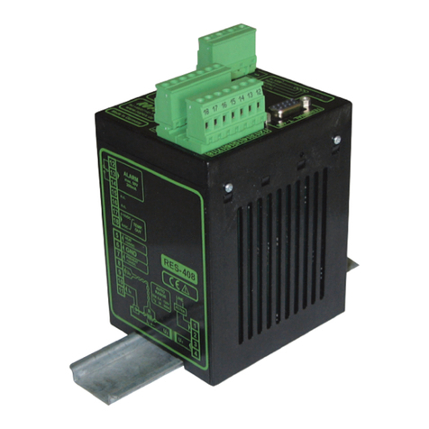
防逆流控制器
Anti-Reverse Power Controller
ZERO PULL
防逆流控制器
Anti-Reverse Power Controller
ZERO PULL
ARPC
ARPC
PV Panels
PV Panels
Grid
Grid
Voltage sample
Voltage sample
Loading limit
Loading limit
提示3: CT不能放到N线和地线上
NOTE3: Don’t place the sensor on the N wire or the earth wire
提示4: CT不能同时穿过L线和N线
NOTE4: Don’t place the sensor on the N and L wire simultaneously.
提示5: CT延长线不能超过100米
NOTE5: The length of CT’s cable cannot over 100m.
防逆流控制器
Anti-Reverse Power Controller
ZERO PULL
ARPC
Voltage sample
4. 连接限载信号线
Connect the loading limit signal wires
连接ARPC COM到逆变器能量管理模块的GND.
Connect ARPC’S COM to the GND pin of the Inverter Power Control Module.
连接 ARPC RY1到逆变器能量管理模块的IN1.
Connect ARPC’S RY1 to the IN1 of the Inverter Power Control Module.
连接 ARPC RY2到逆变器能量管理模块的IN2.
Connect ARPC’S RY2 to the IN2 of the Inverter Power Control Module.
连接 ARPC RY3到逆变器能量管理模块的IN3.
Connect ARPC’S RY3 to the IN3 of the Inverter Power Control Module.
连接 ARPC RY4到逆变器能量管理模块的IN4.
Connect ARPC’S RY4 to the IN4 of the Inverter Power Control Module.
