manuals.online logo
Brands
  1. Home
  2. •
  3. Brands
  4. •
  5. Siemens
  6. •
  7. Controllers
  8. •
  9. Siemens SQD Series User manual

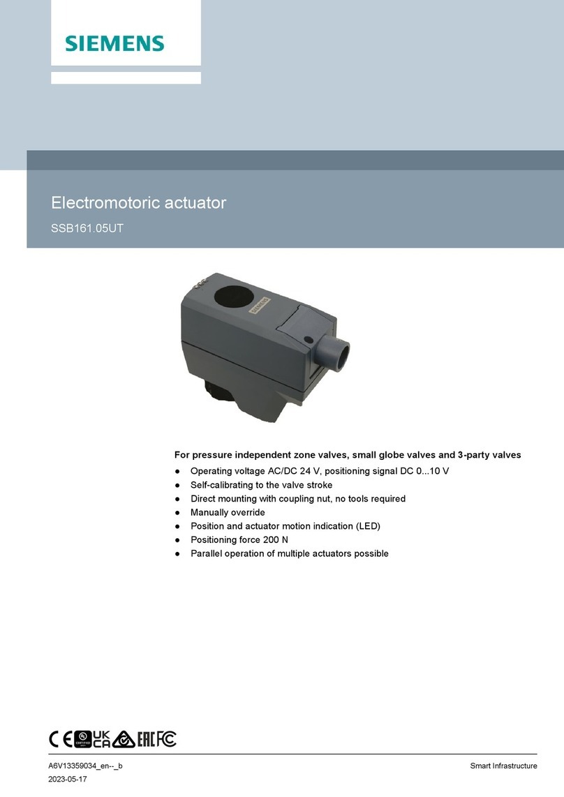
Siemens SQD Series User manual

Installation Instructions
Document No. 129-553
December 22, 2011
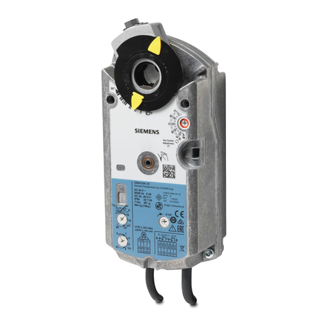
SQD Series Valve Actuators
(For use with 1-1/2-inch to 2-inch Pressure Independent
Control Valves)
Item Number: 129-553, Rev. AA Page 1 of 4
Product Description
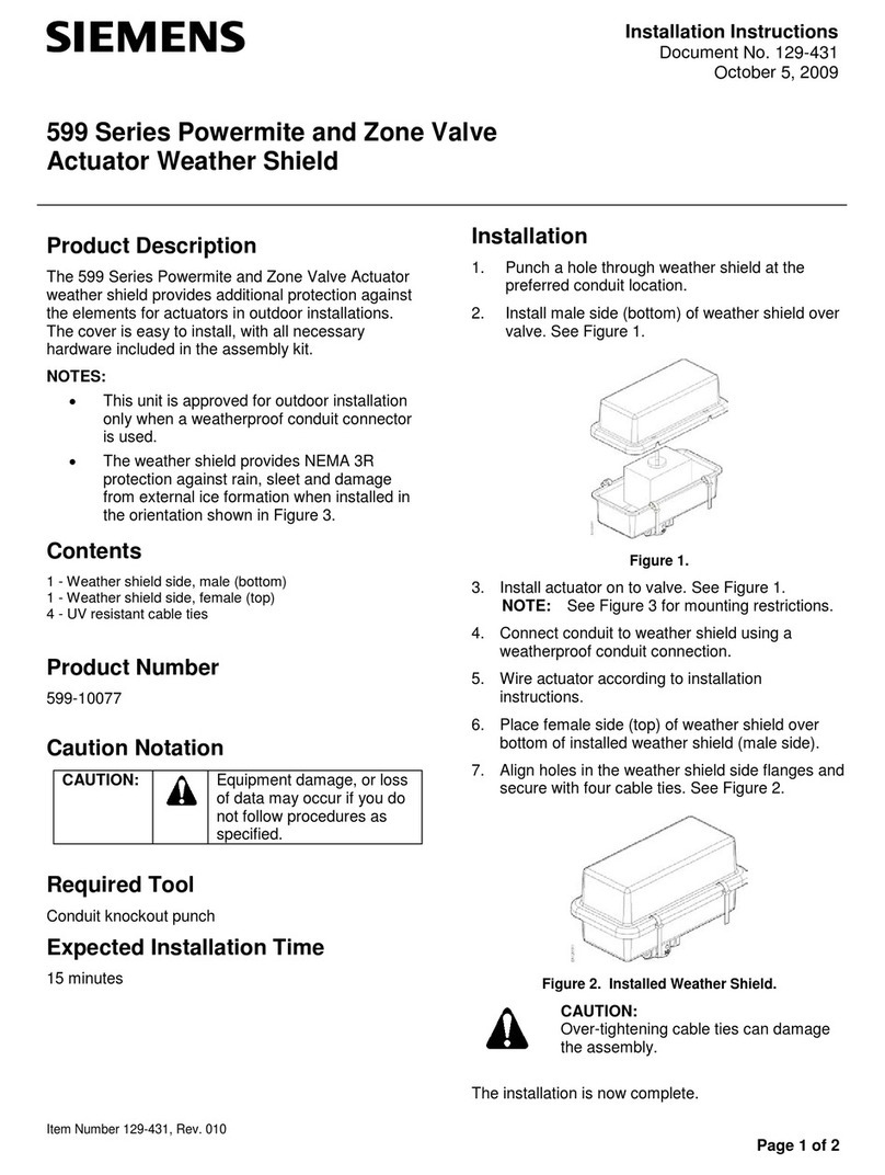
The SQD Actuator requires a 24 Volt power supply
and a 0 to 10Vdc or floating signal to control the
Siemens 1-1/2 inch and 2-inch 599 Series Pressure
Independent Control Valves with 1/4-inch (6.5 mm)
stroke.
Warning/Caution Notations
WARNING: Personal injury/loss of life may
occur if you do not perform a
procedure as specified.
CAUTION: Equipment damage may occur
if you do not perform a
procedure as specified.
Product Number
Description Actuator
Code
SQD65U 0 to 10 Vdc control 235
SQD85.03U 3-position (floating) control 234
Required Tools
•1-1/4-inch open end wrench
•#2 Phillips or flat-blade screwdriver
•Flat-blade calibration screwdriver (3 mm) for
wiring connections
•Wire cutter/stripper
Estimated Installation Time
•15 minutes for wiring a factory-installed
actuator.
•30 minutes for field replacement of actuator.
Prerequisites
WARNING:
If mounting the actuator to a valve
already in line, either close the shut-off
valves in the piping (upstream first,
then downstream) or switch off the
pump to allow the differential pressure
in the valve to drop.
WARNING:
Disconnect the controller power
before replacing the actuator.
90° 90°
EA1326R1
Figure 1. Acceptable Mounting Positions with Valve.
NOTE: Vertical mounting is recommended.
Instructions
If you are mounting an actuator on a new valve, begin
with the instructions, Mounting an Actuator to a Valve.
Remove Actuator from Valve
1. Remove the actuator cover using either a #2
Phillips or a #2 flat blade screwdriver.
See Figure 2.
EA1331R1
M30 x 1.5
1
1
2
1
Figure 2.
2. Disconnect and identify the wires. Place the cover
back on the actuator.
Document No: 129-553
Installation Instructions
December 22, 2011
Remove Actuator from Valve, Continued
3. Use a 1-1/4-inch open end wrench to loosen the
coupling piece.
4. Remove the actuator from the valve.
Mounting an Actuator to a Valve
1. If you are attaching the actuator to a new valve,
remove the protective plastic cap from the valve
stem. See Figure 3.
EA1327R1
VPI45.., VPI45..Q
Figure 3.
2. Turn the manual-positioning knob
counterclockwise to “0”. See Figure 4.
EA1328R1
Figure 4.
3. Place the actuator on the valve. See Figure 5.
EA1329R1
12
Figure 5.
4. Use a 1-1/4-inch open-end wrench to tighten the
coupling piece to a maximum of 22 ft-lbs. See
Figure 6.
EA1330R1
Figure 6.
5. Use either a Phillips head screwdriver or a flat-
blade screwdriver to remove the actuator cover for
access to the terminal block, selector plug, and
jumper wire. See Figure 7.
EA1331R1
M30 x 1.5
1
1
2
1
Figure 7.
6. Attach wires, set the selector plug and if
necessary, cut the R–M jumper. See Wiring.
7. Place the cover on the actuator. The positioning
knob must be at “0” to fit into the shaft. If the cover
does not fit, turn it 180 degrees.
Page 2 of 4 Siemens Industry, Inc.
Document No: 129-553
Installation Instructions
December 22, 2011
8. Fasten the cover with the screws. See Figure 8.
EA1344R1
M30 x 1.5
2
2
1
1
Figure 8.
The installation is now complete.
Wiring
All wiring must conform to NEC and local codes and
regulations.
Use earth ground isolating, step-down Class 2
transformers. Do not use auto transformers.
Determine the supply transformer rating by adding
the total VA of all actuators used. The maximum
rating for Class 2 step-down transformer is 100 VA. It
is recommended that no more than 10 actuators be
powered by one transformer.
SQD65U
To use a 0 to 1000 ohm input signal on terminal R,
the circuit board jumper R—M must be cut.
CAUTION:
If the circuit board jumper R–M is cut, you
cannot wire the R and M terminals on the
terminal block to re-establish the
connection.
The 0 to 1000 ohm signal is additive to the 0 to 10
Vdc control signal. For example, a controller
commanded to 2 Vdc (20%) plus a remote override
input to 300 ohms (30%) results in a position of 50%
stroke.
Figure 9. SQD65U Terminal Connections.
G, G0 24 Vac operating voltage
G System potential
G0 System neutral
Y 0 to 10 Vdc control signal
R Input for 0 to 1000 Ohm remote setting unit or
low temperature detection unit
M Measuring neutral
U Output for 0 to 10 Vdc position indication
WARNING:
Terminal connection G is 24 Vac HOT, not
ground.
CAUTIONS:
•G0 and G must be properly wired for
correct function and full life of the
actuator.
•If the actuator makes a buzzing noise
upon reaching setpoint, G and G0 are
improperly wired and should be
reversed.
SQD85.03U
NEUT
CONTROLLER ACTUATOR
EARTH GROUND
ISOLATING CLASS 2
TRANSFORMER FOR
24 Vac POWER
120 Vac
1
0
Y2
Y1
G
24
Vac
EA0795R1
Figure 10. SQD85.03U Wiring.
G 24 Vac operating voltage (system potential)
Y1 Output shaft extends, valve opens
Y2 Output shaft retracts, valve closes
Siemens Industry, Inc. Page 3 of 4
Document No: 129-553
Installation Instructions
December 22, 2011
Manual Override for SQD65U
Non-Spring Return Troubleshooting
•Check wiring for the proper connections.
•Check selector plug for recommended position.
Turn the manual positioning knob clockwise to move
the actuator stem outward. See •Check for adequate power supply.
Figure 11.
References
Turn the manual positioning knob counterclockwise
to move the actuator stem inward. See Technical Instructions Document Number
Figure 11. SQD Series Electromotoric Actuators 155-777
Pressure Independent Control Series 155-774
Two-Way Brass Valve Bodies,
1/2-Inch to 2-Inch, ANSI 250
Figure 11.
Dimensions
Figure 12. SQD Series Dimensions in Inches (Millimeters).
Minimum access
space recommended
4 inch (100 mm)
8 inch (200 mm)
Information in this publication is based on current specifications. The company reserves the right to make changes in specifications and models
as design improvements are introduced. Product or company names mentioned herein may be trademarks of their respective owners.
© 2011 Siemens Industry, Inc.
Siemens Industry, Inc.
Building Technologies Division
1000 Deerfield Parkway
Buffalo Grove, IL 60089-4513
USA
1-847-215-1000
Your feedback is important to us. If you have
comments about this document, please
send them to
[email protected]
Document No. 129-553
Printed in the USA
Page 4

This manual suits for next models

2

Other Siemens Controllers manuals

Siemens OpenAir GDE Series Owner's manual

Siemens

Siemens OpenAir GDE Series Owner's manual

Siemens instabus Series User manual

Siemens

Siemens instabus Series User manual

Siemens Raja+ 3TE7431-2BC24-1A Series Operating instructions

Siemens

Siemens Raja+ 3TE7431-2BC24-1A Series Operating instructions

Siemens SINUMERIK 840D User manual

Siemens

Siemens SINUMERIK 840D User manual

Siemens Delta Series User manual

Siemens

Siemens Delta Series User manual

Siemens ACR12.3 1 Series User manual

Siemens

Siemens ACR12.3 1 Series User manual
Siemens FC18 Series User manual

Siemens

Siemens FC18 Series User manual

Siemens 72G Series User manual

Siemens

Siemens 72G Series User manual

Siemens Simatic S7-300 User manual

Siemens

Siemens Simatic S7-300 User manual

Siemens SINUMERIK 840D sl User manual

Siemens

Siemens SINUMERIK 840D sl User manual
Siemens 3VL971 Series User manual

Siemens

Siemens 3VL971 Series User manual

Siemens Simatic S7-1500/ET 200MP User guide

Siemens

Siemens Simatic S7-1500/ET 200MP User guide

Siemens Climatix POL822 User manual

Siemens

Siemens Climatix POL822 User manual

Siemens SIRIUS 3RA1.5 User manual

Siemens

Siemens SIRIUS 3RA1.5 User manual

Siemens SIPROTEC 7SJ61 User manual

Siemens

Siemens SIPROTEC 7SJ61 User manual

Siemens RVD230 Operator's manual

Siemens

Siemens RVD230 Operator's manual

Siemens CFG3.F200 User manual

Siemens

Siemens CFG3.F200 User manual

Siemens SITRANS L 7ML5400 User manual

Siemens

Siemens SITRANS L 7ML5400 User manual

Siemens SINUMERIK 840D sl Owner's manual

Siemens

Siemens SINUMERIK 840D sl Owner's manual

Siemens Powermite 599 MT Series Owner's manual

Siemens

Siemens Powermite 599 MT Series Owner's manual

Siemens BACnet ATEC User manual

Siemens

Siemens BACnet ATEC User manual

Siemens SIMATIC S7 User manual

Siemens

Siemens SIMATIC S7 User manual

Siemens SIRIUS 3RW55 User manual

Siemens

Siemens SIRIUS 3RW55 User manual

Siemens SIRIUS S0 User manual

Siemens

Siemens SIRIUS S0 User manual

Popular Controllers manuals by other brands

Furious FPV Acrowhoop v2 Quick connect guide

Furious FPV

Furious FPV Acrowhoop v2 Quick connect guide

Emerson Dixell Wing XW570L Installing and operating instructions

Emerson

Emerson Dixell Wing XW570L Installing and operating instructions

m-Dimension D3208 user guide

m-Dimension

m-Dimension D3208 user guide

BWT Manager Connect Duo instruction manual

BWT

BWT Manager Connect Duo instruction manual

PRECISION DIGITAL ProVu PD6310 instruction manual

PRECISION DIGITAL

PRECISION DIGITAL ProVu PD6310 instruction manual

Vive Comfort TP-S-905 Operation manual

Vive Comfort

Vive Comfort TP-S-905 Operation manual

BBE MOVISTROB Series 2100 instruction manual

BBE

BBE MOVISTROB Series 2100 instruction manual

nilan Compact S CTS 602 installation guide

nilan

nilan Compact S CTS 602 installation guide

Naked NKD-pH Installation & start?up guide

Naked

Naked NKD-pH Installation & start?up guide

ccei Phileo VP operating instructions

ccei

ccei Phileo VP operating instructions

Kramer SL-1N quick start guide

Kramer

Kramer SL-1N quick start guide

Regulus UR1 A-DT Installation and operation manual

Regulus

Regulus UR1 A-DT Installation and operation manual

World Uniqueen EN-508 manual

World Uniqueen

World Uniqueen EN-508 manual

Dynamatic 4000 instruction sheet

Dynamatic

Dynamatic 4000 instruction sheet

Lawler 805 Installation & maintenance manual

Lawler

Lawler 805 Installation & maintenance manual

Minco 820B manual

Minco

Minco 820B manual

Paragon EC7000 Series General instructions

Paragon

Paragon EC7000 Series General instructions

PVR sub-zero NANOCHILL NC-110A user manual

PVR

PVR sub-zero NANOCHILL NC-110A user manual

manuals.online logo
manuals.online logoBrands
  • About & Mission
  • Contact us
  • Privacy Policy
  • Terms and Conditions

Copyright 2025 Manuals.Online. All Rights Reserved.