Sofar SAR-100 User manual
SAR-100

1. About the Manual
1.1 Apply to readers
1.2 Interpretation of Symbols
2. Introduction
3. Parameters
4. Feed-in limitation System Diagram
5. Product installation
5.1 Tool
5.2 Location
6. Device installation procedure
6.1 Check the packing
6.2 Installation
6.3 Internal structure
6.4 Device Wiring
6.5 Inverter address settings
6.6 Change external antenna
7. Networking Configuration
7.1 Wi-Fi Access
7.2 Ethernet Access
8. Feed-in limitation
8.1 Feed-in limitation setup
01
01
01
02
02
04
05
05
06
07
07
08
09
10
12
13
14
14
26
33
33
CONTENTS

9. Instruction for Indicator Light,
Dial Switch and Reset Button
9.1 Indicator Light
9.2 Repeater light
9.3 Dial Switch
9.4 Reset Button
10. SOLARMAN Monitoring
10.1 Register
10.2 SOLARMAN Smart APP
10.3 SOLARMAN Business APP
11. Contact US
38
38
39
39
39
40
40
41
47
54

1. About the Manual
1.1 Apply to readers
This manual is intended for professional personnel who install and operate the
SAR-100.
1.2 Interpretation of Symbols
01
SAR-100 User Manual
©Copyright of Shenzhen SOFARSOLAR Co., Ltd. 01

2. Introduction
02
SAR-100 User Manual
©Copyright of Shenzhen SOFARSOLAR Co., Ltd.
02
02
SOFAR Feed-in limitation box enables the real-time monitoring of grid-tied
situation through the integration of three-phase meter, logger which meets
the requirement of real-time adjusting inverter output power at power
consumption scenario. It can connect to many inverters and support data
transmission via Wi-Fi & Ethernet. It also supports the Feed-in limitation
application of parallel-connected machine for G3 series SOAFR inverters.

03
03
3. Parameter
Parameter
Product Model
Remote Communication
Local Communication
No. of Connections
Accessing Method
Working Voltage
Working Current
IP Grade
Working Temperature
Working Humidity
Installation Method
Size
Weight
SAR-100
2.4G Wi-Fi + Ethernet
RS485
10
Three-Phase Four-Wire
3x230/400V 50/60Hz
3x1.5(6)A
IP65
-25℃~+60℃
5%-95% (No Condensation)
Wall-Hanging
~400*300*170mm
~4.1kg
SAR-100 User Manual
©Copyright of Shenzhen SOFARSOLAR Co., Ltd. 03

If RS 485 link communication is not successful for some inverters, please connect
a 120Ω resistance with repeater and A&B port of the last inverter.
04
04
02
4. Feed-in limitation System Diagram
10
-
+RA RB
G
TA TB
Grid
R
S
T
N
Load
R
S
T
N
R
S
RS485 A
RS485 B
T
N Inverter
R
S
RS485 A
RS485 B
T
N Inverter
S1 S2
P1 P2
S1 S2
P1 P2 S1 S2
P1 P2
L1 L2 L3 N
L1 L2 L3 N
N
10
L2 L3
5 8
L1
2
1
Ia
1 Ic
1 A
24
B
2573 9
Ia
2 Ic
2
Ib
1
46
Ib
2
S1 S2
P1 P2
S1 S2
P1 P2 S1 S2
P1 P2
NL2 L3
5 8
L1
2
1
Ia
1 Ic
1 A
24
B
2573 9
Ia
2 Ic
2
Ib
1
46
Ib
2
A B
N L
TA TB RA RB
V-
GV+
+V -V
OUTPUT DC12V
SAR-100 User Manual
©Copyright of Shenzhen SOFARSOLAR Co., Ltd.
04
05
05
03
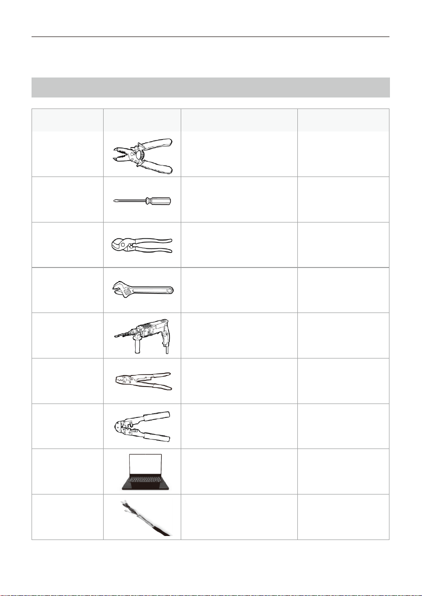
5. Product installation
5.1 Tool
(Shielded twisted
pair)
Diameter: 3-7mm
Tool Name
Wire stripper
Cross
screwdriver
Wire cutter
Adjustable
Wrench
Percussion
Drill
Wire crimper
Crystal head
wire pliers
Computer
COM Line
Usage
Strip cable
insulation
Use to connect
Used to cut power
cables
Use to fix expansion
screws
Use to drillholes
Press line
Pressing crystal head
Use to operate
network configuration
RS485Communication
Picture Remark
SAR-100 User Manual
©Copyright of Shenzhen SOFARSOLAR Co., Ltd. 05
08
08
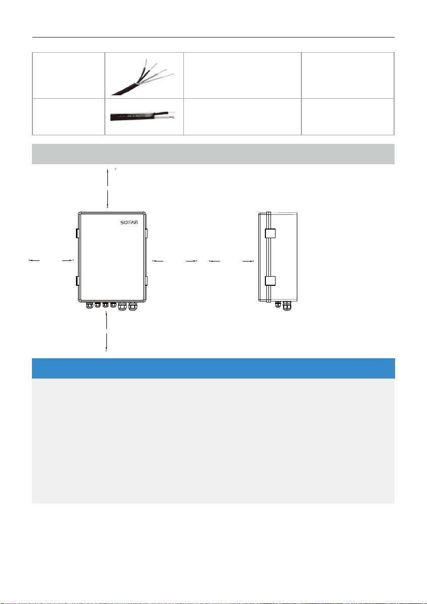
5.2 Location
Voltage-
sampling
cable
Use to connect voltage
sampling signal
Specification:AWG
12-18, 105°/600V
Specification:AWG
16-22, 105°/600V
Use to connect voltage
sampling signal
Double-core
cable
≥ 200mm ≥ 200mm
≥200mm
≥ 500mm
≥ 500mm
Top----200mm;
Below----500mm;
Front----500mm;
Two sides----200mm;
SAR-100 User Manual
©Copyright of Shenzhen SOFARSOLAR Co., Ltd.
06
ATTENTION
· The SAR-100 should be installed indoors at a safe height, avoiding places
with humidity, dust, direct sunlight and corrosive vapors, and should be
shockproof and pressure resistant; the ambient temperature range
should be around -25°C to +60°C.
· Max. communication distance for RS485 should be less than 500m.
· Away from other wiring routes or pipes in doors, such as gas pipe, water
pipe, electric wire and etc.
· Away from metal structure to ensure wireless signal strength.
09
09
02
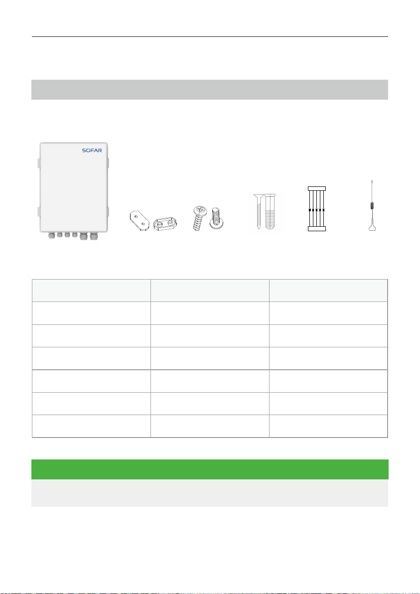
Please ensure that the delivery list items are complete (list below) :
A B C D E F
6. Device installation procedure
6.1 Check the packing
Number
A
B
C
D
E
F
Description
SAR-100
Hangers
Hook screws
Expansion screws
Resistance
Antenna
Quantity
1
4
4
4
5
1
SAR-100 User Manual
©Copyright of Shenzhen SOFARSOLAR Co., Ltd. 07
If any item is damaged or missing, please contact SOFARSOLAR.
NOTE

10
10
08
03
6.2 Device Installation
Step 1: Select a right (firm & flat) place to install the device.
Step 2: Determine the drilling hole positions according to hangers.
Step 3: Fix the device using expansion screws.
SAR-100 User Manual
©Copyright of Shenzhen SOFARSOLAR Co., Ltd.
08
WARNING
· Power off the device before installation.
· Double check the connection before power on the device.
· Please install carefully according to the weight and size of the product
to prevent damage.
· Keep it out of children.
· Please install near the crossroad of grid side and power generation side.
11
11
09
04
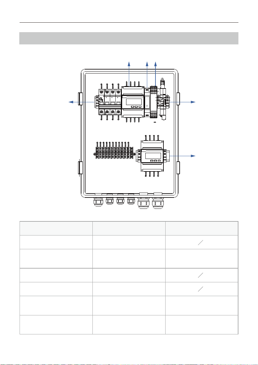
6.3 Internal structure
Number
A
B
C
D
E
F
Module
Air switch
Intelligent three-phase
electric meter
Power module
RS485 repeater
DIN-Rail logger
Intelligent three-phase
electric meter
Description
CT1 Grid side meter
Data transmission
module
CT2 Inverter side meter
A E
F
B C D
SAR-100 User Manual
©Copyright of Shenzhen SOFARSOLAR Co., Ltd. 09
12
12
08
10
05
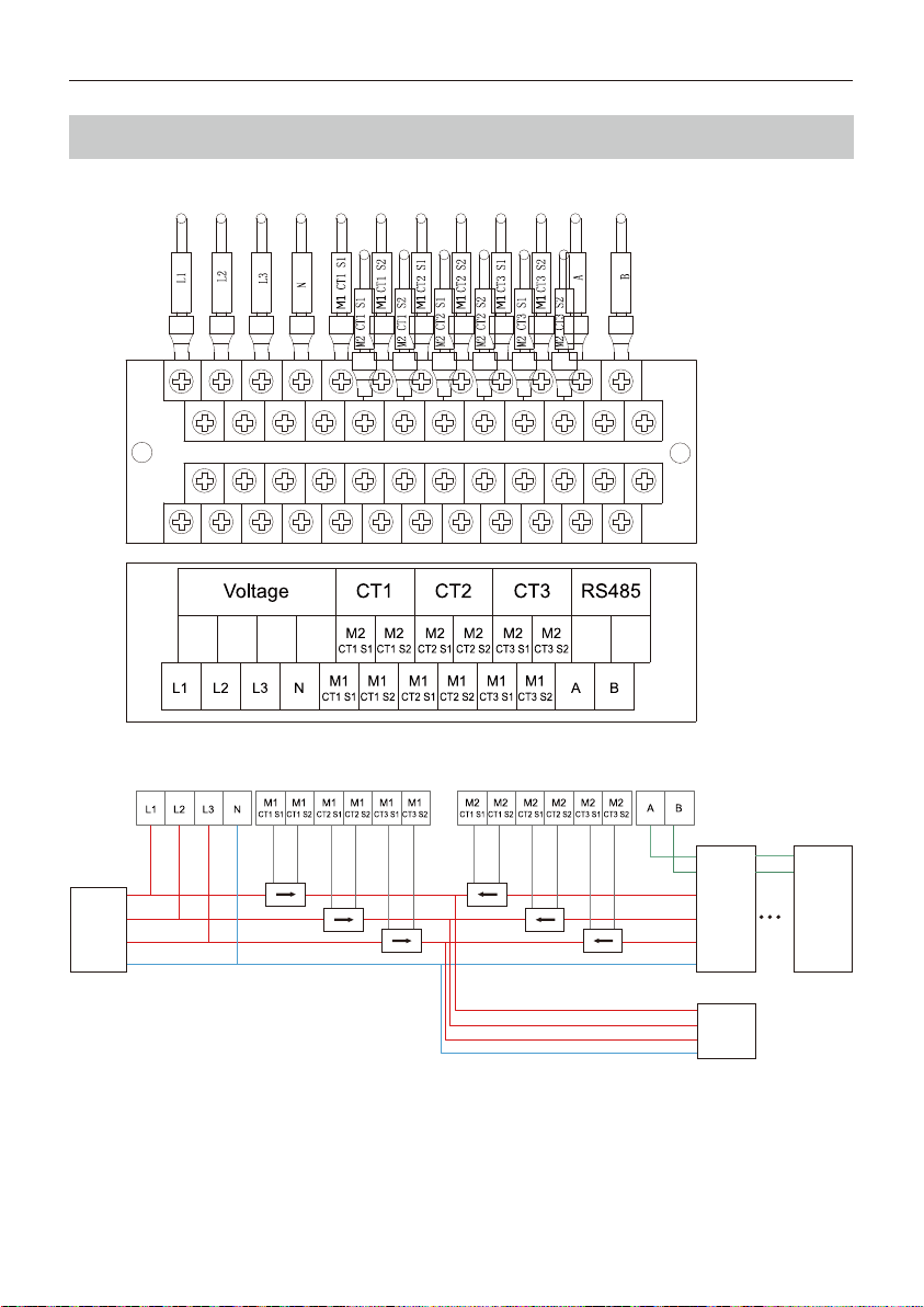
6.4 Device Wiring
Grid
R
S
T
N
Load
R
S
T
N
R
S
RS485 A
RS485 B
T
NInverter
R
S
RS485 A
RS485 B
T
NInverter
S1 S2
P1 P2
S1 S2
P1 P2 S1 S2
P1 P2
S1 S2
P1 P2
S1 S2
P1 P2 S1 S2
P1 P2
SAR-100 User Manual
©Copyright of Shenzhen SOFARSOLAR Co., Ltd.
10

13
13
09
11
06
SAR-100 User Manual
©Copyright of Shenzhen SOFARSOLAR Co., Ltd. 11
Step 1: Connect inverter output to the grid. Connect to phase line R ,S, T, N
accordingly.
Step 2: Connect voltage-sampling signal line, communication distance should
be less than 100m. Connect to phase line R ,S, T, N accordingly.
Step 3: Connect CT, communication distance should be less than10m. CT
direction should be from grid to load and make sure R-phase CT connect
to CT 1-1/2, S-phase CT connect to CT 2-1/2, T-phase CT connect to CT 3-1/2.
ATTENTION
· All electrical installations must be in accordance with local electrical
standards and permission must be obtained from the local electricity
authority before the SAR-100 can be connected to the grid by a
professional.
· When replacing components, ensure that the new replacement
components meet the trial requirements of the SAR-100.
· Ensure that the AC input voltage and current match the rated voltage and
current, otherwise the components will be damaged or will not work
properly.
· Appropriate ESD measures should be taken.
· Please ensure that the following wiring is carried out with the SAR-100
powered off.
· The CT corresponding to M1 is connected to the grid side and S1 and S2 are
connected as shown above with the direction of the arrow pointing from
the grid to the inverter.
· The CT corresponding to M2 is connected to the grid side and S1 and S2 are
connected as shown above with the direction of the arrow pointing from
the grid to the inverter.

14
14
10
12
07
SAR-100 User Manual
©Copyright of Shenzhen SOFARSOLAR Co., Ltd.
12
6.5 Inverter address settings
Step 1: Default address for meter 1 is 1, default address for meter 2 is 100.
Step 2: ①For one inverter, inverter address: 2.
②For multiple inverters, inverter address: 2, 3, 4, 5……
Step 3: No need to set Feed-in limitation function at LCD screen.
• Address cannot be the same.
• Notice: Please make sure local Feed-in limitation function: OFF
NOTE
Step 4: RS485A-B cannot be reversed.
Step 5: All devices can connect to ground line.
· Phase sequence of CT should be consistent with the phase sequence of
voltage-sampling signal. ±1/2 cannot be reversed.
(Select current sensor according to the device capacity.)
NOTE

15
15
11
13
6.6 Change external antenna
Step 1: Unscrew the small antenna of DIN-Rail logger;
Step 3: Screw the external antenna SMA head onto the logger.
Step 2:Thread the external antenna lead through the waterproof joint, insert
the rubber at the bottom of the antenna, and tighten the waterproof cap;
SAR-100 User Manual
©Copyright of Shenzhen SOFARSOLAR Co., Ltd. 13
18
18
11
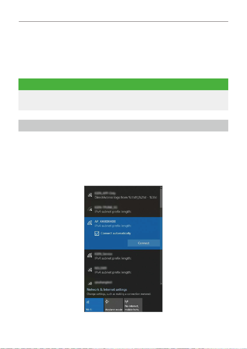
Go to DIN-Rail logger configuration page.
Step 1:Prepare a computer/smart phone that can connect to wireless network.
Step 2: Connect to logger AP (Please do Not connect the cable when configuring
the logger).
Step 3: Select and connect AP XXXXXXXXX in the network list (XXXXXXXXX means
logger SN).
Step 4: Log in to logger WEB page.
Open a browser and enter 10.10.100.254. Username: admin. Password: admin.
7. Networking Configuration
7.1 Wi-Fi Access
• DIN-Rail logger supports Wi-Fi & Ethernet access. Please select
one method to access according to actual situation.
NOTE
SAR-100 User Manual
©Copyright of Shenzhen SOFARSOLAR Co., Ltd.
14
*If the networking configuration is required, please follow the step and the
stick logger along with the inverter does not need to install. If the SAR-100
is only used for Feed-in limitation purpose, users can skip this step directly
and install the stick logger accordingly.

19
19
12
Step 5: During the first login, the browser will remind you whether to save the
password. You can decide according to your usage habit.
Step 6: During the first login, the system will prompt that the AP is not encrypted.
Click “OK” to encrypt it, click “Cancel” if not.
SAR-100 User Manual
©Copyright of Shenzhen SOFARSOLAR Co., Ltd. 15
• Supported browser: IE 8+, Chrome 15+、Firefox 10+
NOTE
20
20
18
13
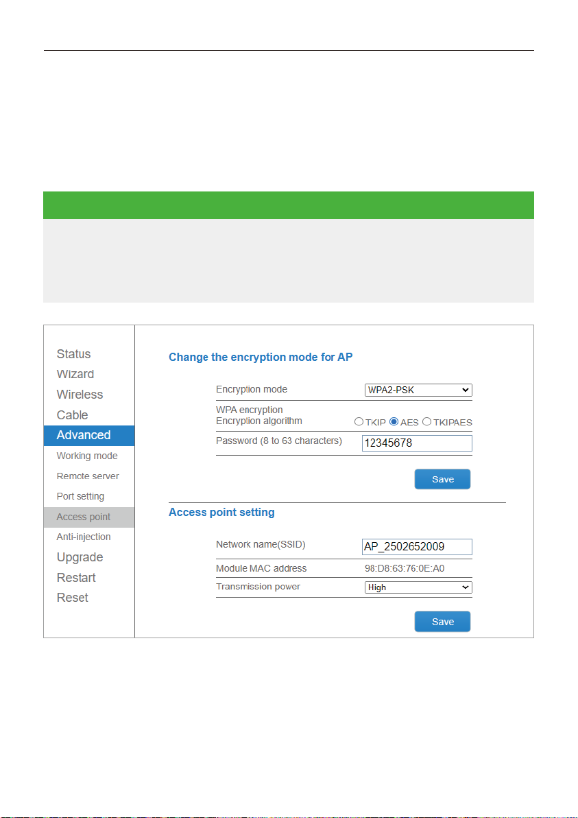
Step 7: If you choose to encrypt AP, you will go to [AP Encryption Modification],
enter your password and click “Save”.
Example: choose WPA2-PSK as encryption mode, AES as encryption algorithm,
password: 1234578 (Please remember the password.)
Users can select encryption mode according to actual situation. After AP has
been encrypted, it requires to connect AP again.
If you forget your password or want to cancel the encryption, please long
press Reset button for 4s to reset which will got to reconfiguration process.
AP password, network information and Feed-in limitation settings will
restore factory settings at this time.
NOTE
SAR-100 User Manual
©Copyright of Shenzhen SOFARSOLAR Co., Ltd.
16

21
21
19
14
Step 8: Click “Reboot” after saving.
SAR-100 User Manual
©Copyright of Shenzhen SOFARSOLAR Co., Ltd. 17
Other manuals for SAR-100
1
Table of contents
Other Sofar Batteries Pack manuals


Popular Batteries Pack manuals by other brands


Jamara
Jamara Ride-On Strong Bull 6V Instruction

DreamGEAR
DreamGEAR ISOUND-4701 user guide

ToughTested
ToughTested TT-PBW-SW8 user manual

Calumet
Calumet Genesis B Power Port user guide

Beckhoff
Beckhoff C9900-U33 Series Installation and operating instructions

King Innovation
King Innovation Insta-Light 75500 quick start guide


