Softel SFT-IPSR33 User manual

IPTV STREAM SERVER
SFT-IPSR33
INTRODUCTION
SFT-IPSR33 is a 2RU rack-mount IPTV streamer server. It is optimal for small and medium internet service
providers to initial setup in large network.
FEATURES
1. Support all kinds of IP protocol
2. Support MPTS/SPTS
3. Support UDP and HLS
4. Support Set Top Box management
5. Support Subtitles and teletext
6. Support theme customization
7. Support channel list management
8. Support channel list management
TO REDUCE THE RISK OF ELECTRICAL SHOCK, DO NOT REMOVE COVER FROM THIS UNIT.
NO USER-SERVICEABLE PARTS INSIDE.
REFER SERVICING TO QUALIFIED SERVICE PERSONNEL.
WARNING:TO PREVENT SHOCK HAZARD, DO NOT EXPOSE THIS UNIT TO RAIN OR
MOISTURE
CAUTION
RISK OF ELECTRIC SHOCK
DO NOT OPEN

SAFETY INSTRUCTIONS
1. Read all safety and operating instructions before you operate the modulator
2. Retain all safety and operating instructions for future reference
3. Heed all warnings on the modulator and in the safety and operating instructions
4. Follow all installation, operating and use instructions.
5. Unplug the modulator from the AC power outlet before cleaning. Use only a damp cloth for cleaning the
exterior of the modulator
6. Do not use accessories or attachments not recommended by us, as they may cause hazards, and will void
the warranty
7. Do not operate the modulator in high-humidity areas, or expose it to water or moisture.
8. Do not place the modulator on an unstable cart, bracket or table. The modulator may fall, causing serious
personal injury and damage to the modulator. Install the modulator only in a mounting rack designed for 19”
rack-mounted equipment.
9. Do not block or cover slots and openings in the modulator. These are provided for ventilation and protection
from overheating. Never place the modulator near or over a radiator or heat register.
10. We strongly recommend using an outlet that contains surge suppression or ground fault protection. For added
protection during a lightning storm, or when the modulator is left unattended for long periods of time, unplug it
form the wall outlet or PDU and disconnect the lines between the modulator and its source. This will prevent
damage caused by lightning or power line surges.
11. Do not overload wall outlets or extension cords, as this can result in a risk of fire or electrical shock.
12. Never insert objects of any kind into the modulator through openings o, as the objects may touch dangerous
voltage and will void the warranty. Refer all servicing to authorized service personnel.
13. Unplug the modulator from the wall outlet or PDU and refer servicing to authorized service personnel
whenever the following occurs:
※The power supply cord or plug is damaged
※Liquid has been spoiled or objects have fallen into modulator
※The modulator has been exposed to rain or water
※The modulator has been dropped or the chassis has been damaged
※The modulator exhibits a distinct change in performance
14. When replacement parts are required, ensure that the service technician uses replacement parts specified by
us. Unauthorized substitutions may damage the modulator or cause electrical shock or fire, and will void the
warranty.
Unpacking and Handling
A full SKD2035 is shipped with all equipment assembled, wired, factory tested, and then packaged in an
appropriate shipping container.
Mechanical Inspection
Inspect the front and rear of the equipment for shipping damage. Make sure the equipment is clean, and no wire,
cable, or connectors are broken, damaged or loose.
Precautions
Avoid heat buildup
Ensure easy access to rack wiring
Facilitate servicing and maintenance
Avoid direct heating or air conditioning
Make sure rack supports are sufficiently rigid to support racks
Beware of dripping water onto equipment form leaky roofs, waveguide roof entries and cold waterpipe
condensations
Damage in Shipment
Should any damage be discovered after unpacking the unit, immediately file a claim with the carrier. A full report
of the damage shall be made and a copy forwarded to Seller.
INSTALLATION
Please follow the instructions below to install the SFT-IPSR33
1. Connect the power plug to the jack. Do not power up the modulator at this step.
2. Connect to the proper earthing wire
3. Connect the video source to the SFT-IPSR33
4. Connect the SFT-IPSR33 to a main switch
5. Power up the streamer
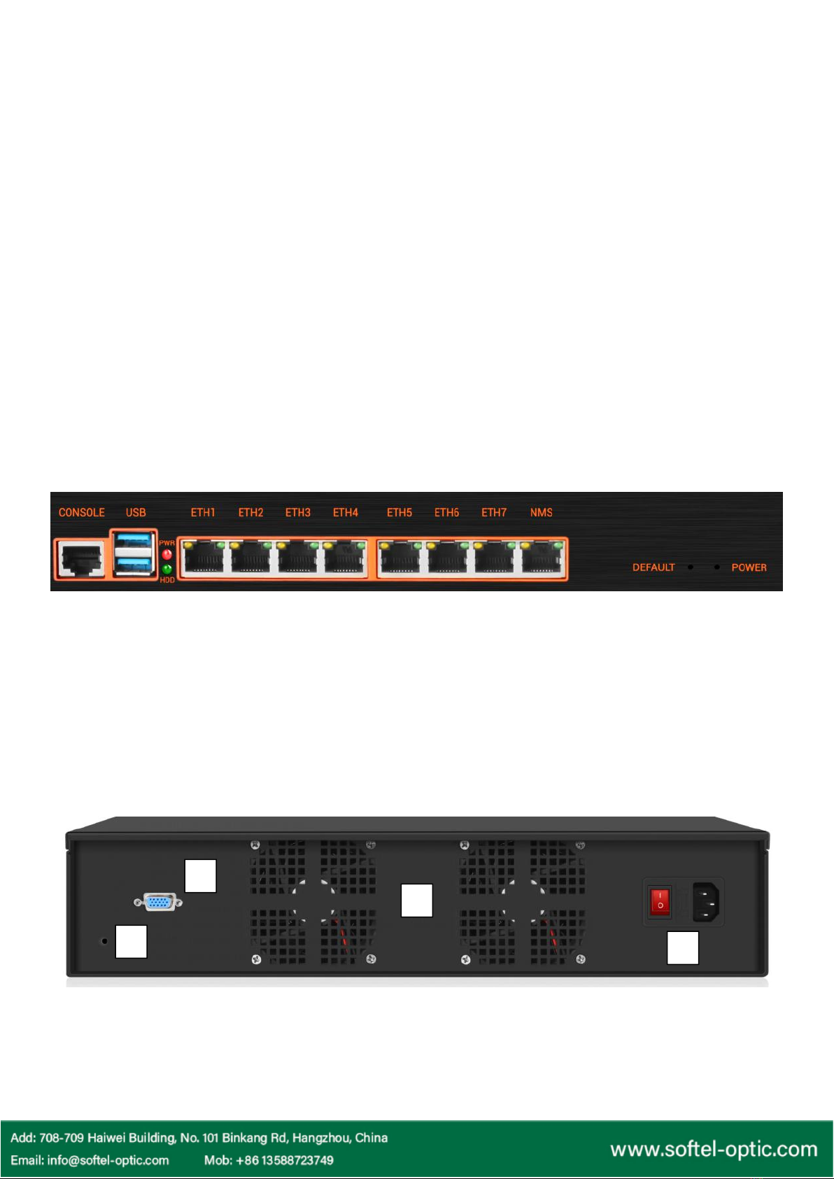
DISPLAY and BUTTONS
1. GND: For grouping
2. VGA: For system monitor
3. Fan: For heat-sinking
4. Rocker switch and power jack
CONSOLE: To log into the basic system
USB: Mouse and Keyboard
PWR: Power on indicate
HDD: Hard dish running indicate
ETH1-ETH6: IPTV signal input
ETH7: IPTV signal output
NMS: Net management system port [IP:192.168.1.30; USER NAME: admin;
PASSWORD:123456]
DERAULT: Press 10s to restore to the factory setting
1
2
3
4
WEB MANAGEMENT
1. Connect the modulator and the computer by the RJ45 port.
2. Open your Google Chrome and input default IP address 192.168.1.30, and press enter.
3. The default user name is user and the default password is user
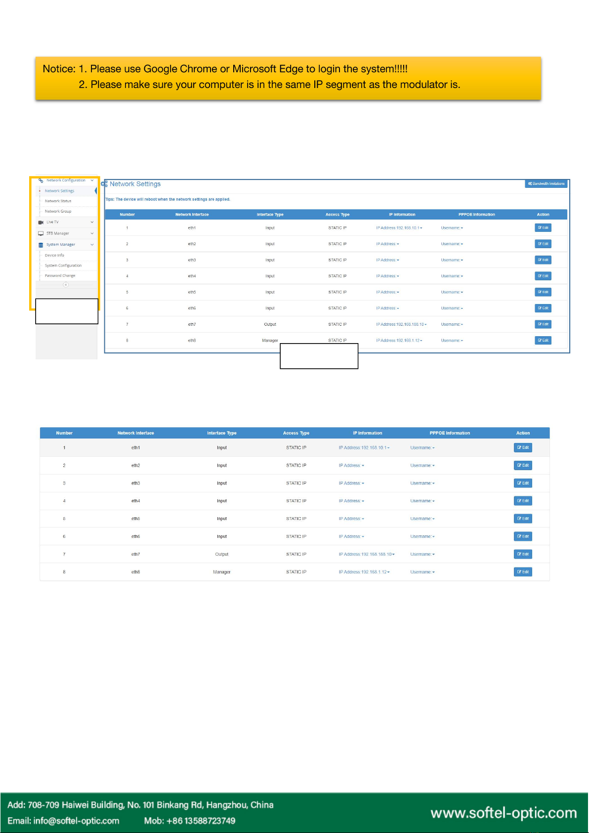
1. Network Configuration
1.1 Network settings
In this page, you can set up the ETH1~ETH7 port
The Menu
Setting Page
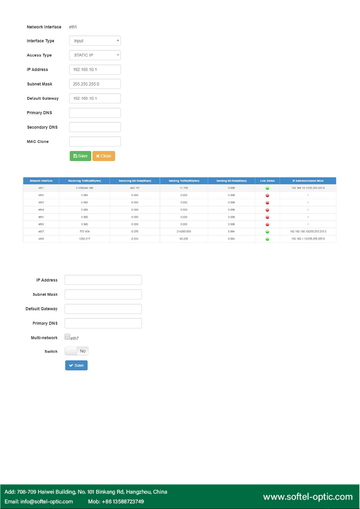
1.2 Network Status
From this page, you can check out the IP stream working status.
1.3 Network Group
1.4 Bandwidth Limitations
We offer this to limit the bandwidth for each port for the better performance.
2. Live TV
There are three menus here. If this is the first time to set up the streamer, you should start with New Channel.
2.1 Channel List
Interface Type: Select from INPUT or OUTPUT type
NOTICE: The ETH1 to ETH7 can be set as input or output.
Access Type: DHCP, STATIC IP AND PPPOE
In DHCP mode, the streamer will get the IP address
automatically. In Static IP mode, the streamer will inquiry
you to input the IP address. In PPPOE mode, please input
the PPPOE username and password.
In this page, you can set up the IP information in group.
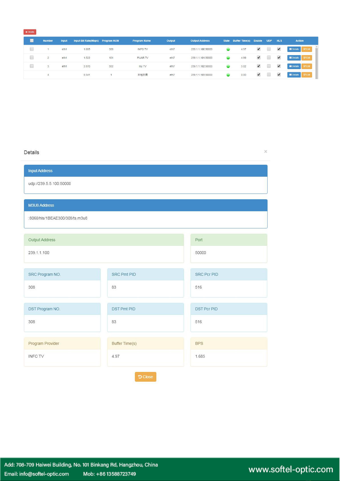
In this page, you can check, edit and delete all the channels
Delete: Delete the selected channel
Square box: Select all. And then click the Delete to delete all.
Enable: To enable the signal output
UDP: Output as UDP
HLS: Output as HLS
Details: See the channel information

Edit: To program the channel
Input: Select the input port
Output: Select the output port
Program Name: Enter the name you like
Program Provider: Enter the name you like
DIP: The destination IP address
DPORT: The destination port
SRC Program No.: The source program number
DST Program No.: The destination program number
SRC Pmt PID: The source PMT PID
DST Pmt PID: The destination PMT PID
SRC Pcr PID: The source PCR PID
DST Pcr PID: The destination PCR PID
This is the audio and video destination PID
2.2 New Channel
To sort out the channel from the IP SOURCE, we should get all the input channel and then select the channels we
want.

Program Analysis
Type of program analysis: Manual Input
Program Forward
After reading the channels, the found channels will be listed here.
Press SOUCE PROGRAM and find Add to add the selected channel to the channel list.
Manual Input:
The streamer will read the date from the port you select and
the IP address you input.
Device Access
The streamer will read the data automatically.
Import File:
This function is to save your work when you have two same
system to install. You can import the channels in Channel
List
Get From Database:
This function is used in China only

2.3 Local Channel
Local channel is to provide extra programs. We can upload the video from the others place and make it as a
channel.
Press New Channel> Input the channel name> Click Upload Video>the streamer will list out the video in the dish.
Select the videos and click Upload.
STB Manager
Here we can manage the set-top boxes.
Add: add a new set-top box
Delete: delete one or selected channels
Batch wifi: set the wifi password
How to add a new STB?
1. Click Add to add a new STB
2.Input Room number and Device number, then Save
STB Upgrade
Here we can upgrade all the STB software.
System Manager
1. Device Info
In this part, we can sort out the set-top
box in group.

2. System Configuration
We offer System Upgrade/Reboot and shutdown here to manage the system.
3. Password Change
Device ID: The unique ID for this device
Connect Switch: Yes
Server IP: For SOUKA CLOUD
Correcting Time: YES to enable the function
Device Time: input the right time for this device
Table of contents


