manuals.online logo
Brands
  1. Home
  2. •
  3. Brands
  4. •
  5. Panasonic
  6. •
  7. Media Player
  8. •
  9. Panasonic FZ-1 User manual

Panasonic FZ-1 User manual

ORDER
NO.
CPD9309012C0
erviceMariual
♦
•
0
-I I
[Q]O~i
DIGITAL AUDIO
Panasonic®
3D0
Interactive Multiplayer
FZ-1
FZ-1
WARNING
■
PRECAUTION
OF LASER DIODE
CAUTION:
This unit utilizes a class 1 laser.
Invisible laser radiation is emitted from the optical pickup Ions whon the unit is turned on:
1.
Do not look directly into the pickup lens.
2. Do not use optical instruments to look
at
the pickup Ions
3.
Do not adjust the preset variable resistor
on
the optical pickup
4. Do not disassemble the optical pickup
unit
5.
If the optical pickup is replaced, use the manufacturm; spucIlIod
111pl11comont
pickup only.
6.
Use
of
control, adjustments or performance of proceduros
otliur
than tho:;o specified herein may
result
in
hazardous radiation exposure.
■
SAFETY
PRECAUTION
1.
Before servicing, unplug the power cord to prevent
an
oloctric shock
2.
When replacing parts, use only manufacturer's rocommondod cornpononts
for
suloty
3.
Check the condition of the power cord. Replace if wear or
durr111!1u
rs
11v1d1111t
4. After servicing, be sure to restore the lead dress, insulation
LH1111ors,
insulation p.tpmn,
:;l11olds.
olc
5.
Before returning the serviced equipment to the customor,
bo
sum
lo
make tho
lollow111!J
11rnulut1un
1usIstanco
test to prevent the customerfrom being exposed to a shock hazard.
• INSULATION RESISTANCE
TEST
1.
Unplug the power cord and short the two prongs of the plug with a jumper wire.
2.
Turn on the power switch.
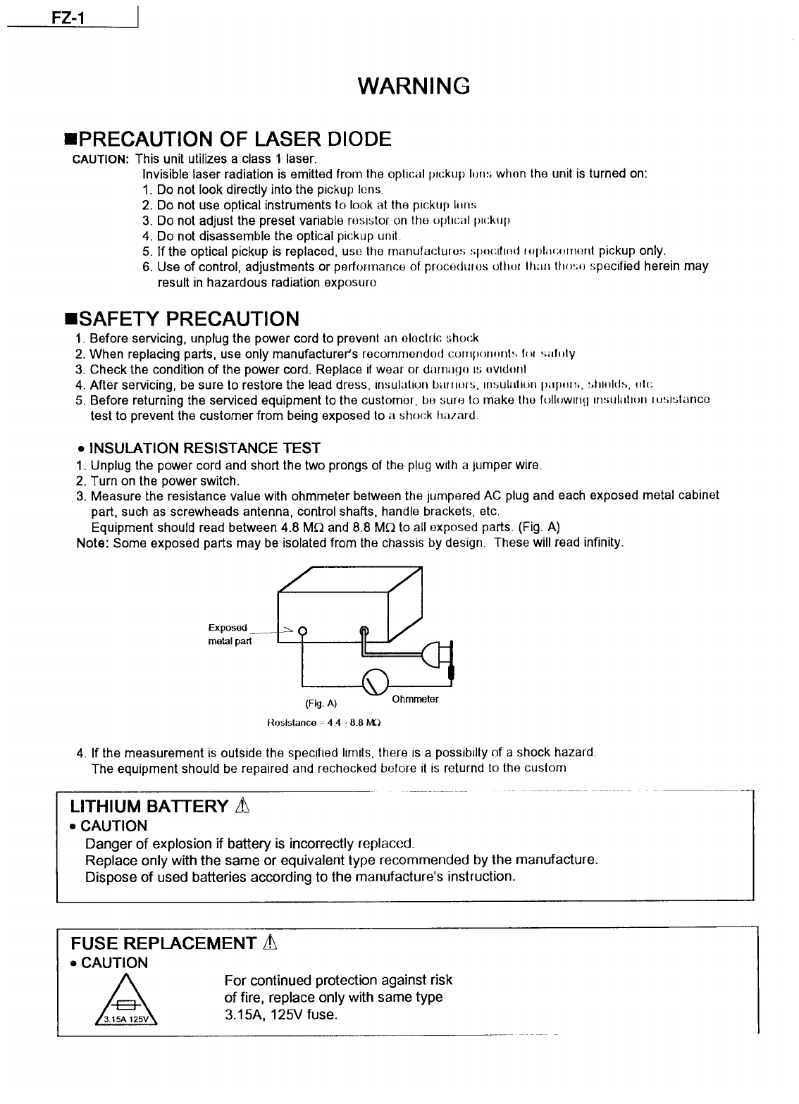
3.
Measure the resistance value with ohmmeter between the jumpered AC plug and each exposed metal cabinet
part, such as screwheads antenna, control shafts, handle brackets, etc.
Equipment should read between 4.8 MQ and 8.8
M!.1
to all exposed parts. (Fig. A}
Note: Some exposed parts may be isolated from the chassis by design. These will read infinity.
Exposed---+-~
metal
part
(Fig. A)
Heslstance
=
4.4 -8.8
tvl"l
4.
If the measurement
is
outside the specified limits, there
is
a possibilty of a shock hazard.
The equipment should
be
repaired and rechecked before it
is
returnd to the custom
,----------------------
---------······-
---
----·
LITHIUM BATTERY
it
• CAUTION
Danger
of
explosion if battery
is
incorrectly replaced.
Replace only with the same
or
equivalent type recommended by the manufacture.
Dispose
of
used batteries according to the manufacture's instruction.
FUSE REPLACEMENT
it
• CAUTION
For continued protection against risk
of
fire, replace only with same type
3.15A, 125V fuse.
1.
System
Overview
1-1. 3DO Overview
1-2. Specifications
Contents
1-3. Location
of
Controls and Components
1-4. Block Diagram
1-5. Block Explanation
2.
Checking
Information
2-1. Handling Precautions for Traverse Deck
2-2. Disassembly / Reassembly
2-3. Troubleshooting Flowchart
2-4. Interconnection for Operation Check
2-5. Terminal Function
of
IC's
2-6. Pin Configurations
of
PCB
3.
Diagrams
and
Replacement
Parts
List
3-1. Wiring Connection Diagram
3-2. Schematic Diagrams
3-3. Printed Circuit Boards
3-4. Exploded Views
3-5. Replacement Parts List
/1-1
/1-1
/1-2
/1-4
/1-6
/2-1
/2-2
/2-12
/2-13
/2-14
/2-24
/3-1
/3-2
/3-10
/3-12
/3-14
FZ-1
FZ-1
1. System Overview
1-1. General Description
The FZ-1
is
a high performance audio/video entertainment and education system capable
of
realistic
interactive video and CD-quality audio presentations.
The FZ-1 will play standard audio CDs at full 16-bit precision and bandwith like audio stereo CD player.
Also display and play Kodak Photo CD disc and Portfolio photo CD disc (Photo with CD sound}.
The FZ-1 will produce NTSC (composite video}, S-video and
RF
modulated composite video outputs to
almost broadcast quality.
1-2. Specifications
CPU CPU 32-bit RISC processor ARM60 (12.5 MHz)
Memory
RAMNRAM
3 MB (Total} 2 MB: Main-RAM
1
MB:VRAM
SRAM
32
KB (Batterv back up}
ROM 1 MB
DSP (Digital Si inal Processor) Original 16-bit digital signal processor
Video/Audio Video output Composite video, NTSC (RS170A standard}
$-Video, NTSC
RF
Video, NTSC, Channel 3
or
4 (Switch selectable)
Resolution 640 (H)
x
480 (V) dots (Inside 320
x
240 dots)
Colors Max. 16.7
Million/
Std. 320K (Pixel Clock: 12.3 MHz)
Audio Stereo 16-bit (CD single) PCM (Sampling: 44.1 KHz)
Storage CD-ROM drive Size: 4.7 and
3.1
inch (12 and 8 cm}
Double Speed CD-ROM Drive (Read Buffer: 32 KB)
Extension memory (via Expansion Port)
1/0 Port Control port Low speed 1/0: Dsub 9-pin
x
1
Daisy-chain system
Expansion port High speed 1/0: 30-pin
x
1
AV
Expansion port Hiqh speed AV-I/O (FMV cartridqe) : 68-oin
x
1
System System dimensions 11.2
x
10.6
x
3.5 inch (284
x
268
x
88 mm)
(W X
DX
H)
Weight 3.0 Kg (6.6 lbs.}
Power reauirement
120VAC
Power consumption
30W
Indicator Power indicator Red-LED
x
1
CD-access indicator Green-LED
x
1
Temperature Operating 50 °F to 95 °F (10
°C
to 35 °C)
Storage -4 °F to 140 °F (-20
°C
to 60 °C} (When packed for shipment)
FMV: Full Motion Video
1 -1
1-3. Location
of
Controls and Components
• Front View
• Rear View
Power switch {POWER)
Ready indicator
{READY)
Lights up when
power
is
on.
Expansion Port
{EXPANSION}
Slot for peripheral devices which
utilize high speed data transfer.
Channel
3/4
switch
{CH
SELECT}
When connecting
an
RF
cable,
specifies whether to use channel 3
or channel 4 as the output channel.
Disk
tray
Extended and retracted using
the OPEN/CLOSE button.
Controller
port
{CONTROLLER}
Dedicated port for the
provided controller.
S-video
output
jack
{$-VIDEO OUT)
Disk tray open/close switch
{OPEN/CLOSE)
CD access indicator
{ACCESS}
Lights up when CD is being
accessed.
When using a television which
supports S-video, connecting a
separately sold S-video cable
results
in
a sharper picture.
Power
cord
Right/left
audio
output
jack
{AUDIO OUT
R/L)
RF
output
jack
{RF
OUT)
Video
output
jack
When connecting with a television
which does not have
an
audio/video
jack, the provided
RF
cable is used.
1 -2
{VIDEO OUT}
FZ-1
• Right Side View
AV
expansion
slot
(AV-EXPANSION)
Dedicated slot, visible upon opening the cover, used with
separately sold FMV cartridges.
/\~--,
I
,-
---
--"'\
I I
-
I I
I
0
------
0
I
II I I
I
I I
j\...
______
../1
II
II
'------_,)
Extension
port
{EXTENSION)
Participation
by
more than one player is
achieved by connecting a separately sold
controller to this port.
\
Left
shift
button
{L)
Connector
Connected to the Multiplayer
unit.
X
button
(X)
Headphone
jack
{PHONES)
Headphones, when used, are
connected to this port.
Volume
{VOLUME)
Used to adjust volume when
using headphones.
Play/pause
button
{P)
1 - 3
FZ-1 FZ-1
1-4. Block Diagram
-
- -
M
AIN
LOGIC
PC
8
-
CD
-ROM Drive
0
I
VBACK
+5V
I i
SRAMCSB
f
IC350
IC400
ICIOO
IC
340
DA58257AM2TS
DABA6162FT2E
ri
DA86C06020XV
MASK
ROM
SRAM
Bock-up
LT
CPU
1024KX8bit
32
K X8
bit
Control
BT400
A
0-31
'
j.
'~
'~
I
Lithium
0
(\I
X
D0-31
A2-19
DO-D7
A2-19
D0-7
-
,
Address
,
Ir
Doto
~
'
'
'.
'
,,
Slow
BUS
32
I/
av
6/
/
/
/
,,
,. ,.
,.,
,.
,,
'
I
-
-
N
::c
~r
ICl20
IC
140
X
140
oo
DAl205FDBXOZ
DAl205GDBXOZ
ri
24.
5454
MHz
6L
D
System IC MADAM
System
IC
CLIO
LI
IO
IC200
-
DA4316VSE2XO
~
16
bits
Audio
DAC
Buffer
-~
~
h
j.
IC210 0
36
/
32
/
Doto/
32/
/
Serial
X200
/
Doto
Address
16.9344
MHz
-
1MB
, '
I
I I
I
I
I
I
I
I
I
-
I
I
C300,
1
302,320,322
...
I
DA8182517JTJ
2M-bit
VRAMX4
CN300,320~
... I I
--
---,
===~
:=i7
--
CN30
I,
321-------
' t
1
2MB
Ii
I I I,
DRAM
PCB
-
IC
310,311,330,331
I
'l_
-
MN4I4270SJ08
4M-bit
DRAM x4
-
1 -4
CN2
.--,CNI
-
'•'
~-
CN620
, •
CN630
-~
~~-
-m
'
Battery)
Ir
IC600
DA623827PFJ
--
CD-ROM
Interface
-
Gate
Array
L/R
IC220
-
DA324DL-O
Monaural
-
OP-AMP
Composite
ICISO
DA9101
KPF-XN
Digital
Color Encoder
Y/C
-
I
-
-
Open/Close
SW
Power
SW
1
SW6C>~
•sw51
Porwer
,
+9V
Power
Supply
+5V
,
+5V
LD630"'633
,..
0630
INDICATORS
L/R
Mute Circuit
0220,
240,
260
Video Amp
0500~502
Monaural
IC520
Transformer
CNI
r
-
CN660
-
-
+9V
I
CN700
......
1
,,
-
-
..
-
CN640
-
~
CN5001
@
~
I
0
-
-
00
-
0 0
-
D
I
-
AC
p=(
===-
===-
~
FAN
MOTOR
AV
EXPANSION
POR
(
FMV
CARTRIDGE
T
TERFACE)
IN
(
68-pin
l
EXPANSION
PORT
(
30-pin
l
RIGHT/
LEFT
AUDIO OUTPUT JACK
VIDEO
OUTPUT
JAC
K
S-VIDEO
OUTPUT
JACK
RF
MODURATED
@
VI
DED OUTPUT
Composite
ENC-
36402
( RF OUTPUT JACK )
RF
Modulator
-
]
CHANNEL
3/4
SWIT
CH
-
I
CN901
~N
9
00
0280,281
CN541
I/
-r
~
1 .
Oo
1,
~I
1
go
coNTROLLER
PORT
-
~
J -
00
(
9-pln
D-
sub l
00
~
CONTROLLER
PORT
PCH
1 -5
1-5.
Block
Explanation
CPU
CPU
is
ARM60.
This
RISC
type
micro
processer
has
32-bit
address
and
32-bit
data
path.
MADAM
supplies
CPU
with
12.5
MHz
clock.
ROM
1
MB
ROM
stores
the
system
management
program.
The
ROM
is
connected
to
Slow
bus
and
its
data
is
read
by
MADAM
and
MADAM
arranges
8-bit
data
into
32-bit
word
and
send
it
to
CPU.
SRAM
32
KB
SRAM
is
connected
to
Slow
bus.
Since
Lithium
battery
backs
up
SRAM
while
power
is
down,
SRAM
can
retain
data.
It
may
be
used
to
back
up
game
data,
for
example.
DRAMNRAM
DRAM
and
VRAM
is
used
as
main
memory.
VRAM
is
dual-port
memory.
This
means
one
port
is
used
as
normal
DRAM
and
the
other
one
is
used
to
read
and
write
data
simultaneously
with
the
former
port.
Therefore,
it
is
used
as
Frame
Buffer
which
is
required
fast
access.
MADAM
MADAM
is
Address
Engine.
It
includes
OMA
logic,
CPU
control
logic,
bus
sharing
logic
and
Cell
Engine.
A oscillator
provides
MADAM
with
50
MHz
clock,
and
MADAM
divides
it
by
two,
and
it
provides
CLIO,
CPU
and
CD-ROM
interface
with
25
MHz
clock.
CLIO
CLIO
is
Data
Engine.
It
includes
pixel
decoding
logic,
16-bit
Digital
Signal
Processer
and
video
interface
logic.
With
a
crystal,
CLIO
oscillates
24.5454
MHz
clock
and
supplies
MADAM
with
24.54
MHz
and
supplies
Digital
Color
Encoder
with
12.27
MHz.
Digital Color Encoder
CLIO
supplies
Digital
Color
Encoder
with
RGB
data
and
some
control
signals.
And
Digital
Color Encoder
modifies
them
into
NTSC
signals.
It
outputs
both
composit
signal
and
Y/C
signal.
Audio DAC
16-bit
Audio
DAC
converts
digital
audio
data
from
CLIO
into
analog
audio
data.
CLIO
sends
DAC
data
with
serial
communication
manner.
CD-ROM interface
CD-ROM
interface
Gate
Array
is
the
interface
between
CLIO
and
both
internal
CD-ROM
drive
and
External
drives
which
are
connected
through
Expansion
Port.
1 - 6
FZ-1
FZ-1
2. Checking Information
2-1. Handling Precautions for Traverse Deck
The laser diode
in
the traverse deck (optical pickup) may break down due to potential difference caused by static
electricity of clothes or human body.
So,
be
careful of electrostatic breakdown during repair of the traverse deck (optical pickup).
• Handling
of
traverse
deck
(optical pickup)
1.
Do
not subject the traverse deck (optical pickup)
to static electricity
as
it
is
extremely sensitive to
electrical shock.
2.
To prevent the breakdown of the laser diode,
an
antistatic shorting pin
is
inserted into the flexible
board (FPC board).
When removing or connecting the short pin, finish
the job
in
as
short time as possible.
3.
Take care not to apply excessive stress to the
flexible board (FPC board).
4.
Do not turn the variable resistor (laser power
adjustment). It has already been adjusted.
•
Grounding
for
electrostatic
breakdown
prevention
1.
Human body grounding
Use the anti-static wrist strap to discharge the
static electricity from your body.
2.
Work table grounding
Put a conductive material (sheet) or steel sheet
on
the area where the optical pickup
is
placed,
and
ground the sheet.
Caution:
The static electricity of your clothes will not
be
grounded through the wrist strap. So, take care not to
let your clothes touch the traverse deck (optical pickup).
FPC boards
Lens (Do not touch) (Handle then carefully)
I
Traverse Deck Variable resistor Be sure to short this portion
2 -1
(Do not touch) (Use the shorting
pin
or clip)
Wrist strap
(Anti-static bracelet)
Iron plate or some metals
to conduct electricity
2-2. Disassembly/ Reassembly
Note:
Before disassembling,
be
sure to perform the following procedures first.
1.
Remove the CD-ROM disk if it
is
inserted
in
the CD-ROM drive.
2.
Turn the power swith off.
3.
Disconnect the AC power cord.
4.
Remove the optional units.
Caution: Please follow directions carefully.
Do not interchange screws
in
any part of the system.
Top Case
Figure 1
CD-ROM Drive
CD-ROM
Drivewith
Shield Panel
Figure 2
Figure 3
None Printing Side
(1) Turn this unit (FZ-1) upside down and place
it on a flat surface.
(2) Remove four screws
<.A>
(3
x
14 mm)
as shown
in
Figure 1.
(3) Turn it over again and gradually raise the
top case.
*Reassemble
in
the reverse order.
(1)
After removing the top case, remove
two screws <B> (2.6 x 6 mm) as shown
in
Figure
2.
(2) Remove four screws <C> (2.6
x
8 mm)
as
shown
in
Figure
2.
(3) Gradually raise the front end of the CD-ROM
drive
and
then disconnect the flat cables from
two connectors (CN 620,
CN
630)
as
shown
in
Figure
3.
---,
I
I
~
I
I
CN630
~
:
I
CN620
I
l
_________
J
2-2
FZ-1
FZ-1
Cushion
Fan Motor
Figure 4
Power
Transformer
AC PowerCord
,,,,.-~"
0\
\
CD
I
CN1
'\.
/
......__
_
---
Figure 5
Fan
Motor
r-----1
I w
CN660
I
,________,~
I ~,,,,.....=~~
I
rtt
$,'1.---------'
1---i
I
I
I I
\..______
./
Figure
6
2-3
(4) Unhookfour hooks <D> as shown
in
Figure
4.
(5)
Raise the CD-ROM Drive shield plate.
*Reassemble
in
the reverse order.
(1) After removing the top case and the CD-ROM
drive, remove two screws <E> (3 x 10
mm),
then disconnect two connectors (CN
1,
CN
3)
as shown
in
Figure
5.
(2)
Raise the power transformer (with the
AC power cord).
*Reassemble
in
the reverse order.
(1)
After removing the top case. the CD-ROM
drive, and the power transformer, disconnect
the connector (CN 660) as shown
in
Figure
6.
(2) Remove the fan motor.
*Reassemble
in
the reverse order.
DRAM PCB
OPEN/CLOSE Button
Power
Button
Figure 7
Light Leading Panel
-
----
I Hooks
\..
_________
...)
Figure 8
Shleld Plates
Figure 9 <F>
2-4
(1) After removing the top case, the CD-ROM
drive, the power transformer, and the fan
motor, raise the power button and the
open/close button as shown
in
Figure 7.
FZ-1
(2)
Gently pull out the light leading panel from the
bottom cabinet while pushing two hooks as
shown
in
Figure
8.
(3) Remove all thirteen screws <F> (2.6 x 8 mm)
as shown
in
Figure
9.
(4) Carefully raise two shield plates.
FZ-1
Long-nose plier
r--
1D
I
I
I
7
I
I
I
l==:;=:====:::=-::::::~.::=I
L
---
_J
Main PCB
Hook
Figure 10
Main PCB
Hook
Main PCB <G>
AV
Connector Plate
FMV
Connector Plate
Figure
11
--......___
// 8
'\
I
i).
\
Main PCB \ I
CN541 /
Figure 12
2-5
(5) Unhook the hook, then raise the DRAM
PCB as shown
in
Figure 10.
*Reassemble
in
the reverse order.
(1) After removeving the top case, the CD-ROM
drive, the power transformer, the fan motor,
and the DRAM PCB, remove screw <G> (2.6
x 8 mm), then remove the
AV
connector plate
and the FMV-connector plate as shown
in
Figure 11.
(2) Disconnect the flat cable from connector
(CN 541).
(3)
Gradually raise the front end of the main PCB
and remove it from bottom cabinet as shown
in
Figure
12.
*Reassemble
in
the reverse order.
Controller Port PCB
Controller
Port
PCB
,-----
---,
I I
I
I
I
I
I
I @ @ I
1-------'
\...
________
_)
Figure
13
CD-ROM
Drive
(1) After removing the top case, the CD-ROM
drive, the power transformer, the fan motor,
the DRAM PCB, and the main PCB, gradually
raise the Controller Port PCB as shown
in
Figure 13.
*Reassemble
in
the reverse order.
Precaution
for
replacing
the
CD-ROM
Drive
Mechanism
When replacing the Mechanism (PIN: LMXY0055), the Solder and the Lens Cap should
be
removed as shown below.
Remove the Solder from the solder point.
r-------,
,------7
:=tJSolderPoint
I
I I
I
(•'
I
I
~/
I
I I
L
______
J
: =tJSolder
Point :
¢
,:
F,\\
:
1_1
I
I I
L
______
_J
Remove the Lens Cap from the Optical Pickup.
2-6
,-------,
I
L~--:::==-cr;;,--
I
¢ l
_:;,--=-_,.__--"_"--
I
-C::====='
I
L
_______
J
FZ-1
FZ-1
Figure
22
CN5
Figure
23
•
Mechanism
Reassembly
Traverse Deck
Figure
25
2-9
(5) Disconnect the connector (CN 4) as
shown
in
Figure 22.
(6) Turn the CD-ROM Drive Unit upside
down and remove four screws <E> (2.6
x 8 mm)
as
shown
in
Figure 23.
(7) Disconnect two connectors (CN
5,
CN
7) as shown
in
Figure 23.
(8) Gradually raise the PCB and then
disconnect two connectors (CN
3,
CN
6)
as shown
in
Figure 24.
(9) Remove the PCB.
(1) After removing the Tray, unhook two
Hooks securing the Traverse Deck as
shown
in
Figure 25.
Figure 26
CD-ROM Drive Unit
\
PCB
CN7
Figure
27
Figure 28
Flat
Cable'<
-
'\
(
'1:J~CN3
I
""
I
I
Figure 29
2-10
(2)
Remove the Traverse Deck.
(3) Turn the CD-ROM Drive Unit as shown
in
Figure 27.
(4) Secure the PCB with four screws <F>
(2.6
x
8 mm)
as
shown
in
Figure 27.
(5)
Connect the connector
(CN
7) as
shown
in
Figure
27.
(6)
Turn over the CD-ROM Drive Unit
again.
(7) Connect the connector
(CN
4)
as
shown
in
Figure 28
(8)
Connect the flat cable to
CN
3 as
swown
in
Figure 29.
FZ-1
FZ-1
r-----,
I
~I
I I
I
fnl
t
I
_,I-'-'--'----
I
I I
{J, I
• I
I
/f(]IL:
I_.
....
~--
I I
'---
___
)
Flat
Cable~
-
"-
\
/
::..VN6
\
Figure 30
Figure
31
Figure
32
CN5
Figure 33
\ rt:? I
'-
/
_
__,,
r---
--,
I
---Q::::i
I
I _::jrl',] I
I --1.1.Ll_ I
I I
I
◊
•
=1fp~1_
I
I
'---
-
__
J
2 -
11
(9) Connect the flat cable to
CN
6 as
swown
in
Figure
30.
(10) Fit the front end of the Traverse Deck
as shown
in
Figure 31.
(11) Lock the rear end of the Traverse
Deck
as
shown
in
Figure 32.
(12) Turn the CD-ROM Drive Unit.
(13) Connect the connector
(CN
5)
as
shown
in
Figure
33.
2-3.
Troubleshooting
Flowchart
Start
END
NO
>--
Check Power Logic.
Check CLIO and
.:-----ll~
Video Process
Section.
Check CD-ROM
>-----ll~
Drive and CD-ROM
Drive Interface.
2-12
The following main parts
and
portions should
be checked:
Power Logic
IC11
T1
IC31
D1
F1
D2
SW51
(Power Switch)
Memory Section
--------..
IC
300,302,320,322
IC
310,311,330,331
CN300,301,320,321
CLIO and Video Section
------..
IC180, IC140
IC300,302,320,322
L180, CNS00
Sound Process Section
------..
IC200
0200
IC140
0240
0260
0270
FZ-1
CD-ROM Drive and CD-ROM Drive Interface
-----..
CD-ROM
Drive----
Mechanism
CD-ROM Drive
PCB.
CD-ROM Drive Interface
Flat Cables Q630
IC120 CN620
IC600 CN630
Controller Port and MADAM
---
CN900,
901
IC120
CN541
IC200
FZ-1
2-4. Interconnection of Operation Check
CD-
ROM DRIVE
EXTENSION CABLE
(12-
PIN)
(P/N DFWV95C0079)
CD
-ROM DRIVE
EXTENSION CABLE
(30-
PIN)
(P/N DFWV95C0080)
CN640
··············30
CN620
MAIN LOGIC BOARD
CD-
ROM DRIVE
~...:'....'-=======I
O
l=========I
AV
EXPANSION SLOT
CN1
CN3
[gl
CN660 CN700 TO OPTIONAL
FMV CARTRIDGE
POWER SWITCH
CONTROLLER
PORT PCB
CONTROLLER PORT
2 - 13
SW600
DISC TRAY OPEN/CLOSE SWITCH
2-5. Terminal Function of IC's
IC100
CPU (P/N: DA86C0602XV)
Pin 1/0 Pin Name Comment
No.
1 1/0,
TTL
D27 Data Bus
2"''
2 1/0,
TTL
D28 Data Bus 2
26
3 1/0,
TTL
D29 Data Bus 2
29
4 1/0,
TTL
D30 Data Bus
2;,u
5 1/0,
TTL
D31
Data Bus
2~
1
6 In,
TTL
CPA
Coprocessorabsent
7
Vss
8 Vdd
9 Out LOCK Locked Operation
10 In,
TTL
BIGEND Big Endian configuration
11
Out CPI- Coprocessor Instruction
12 In,
TTL
DBE Data Bus Enable
13 Out
WORD
Byte-/Word
14 In,
TTL
MCLK Memory Clock input
15 In,
TTL
WAIT- Wait signal input
16 In, TTL LATEABT Late Abort input
17 In,
TTL
PROG32 32-bit Program configuration
18
In,
TTL
DATA32 32-bit data configuration
19 Out WRITE Read -/ Write
20 Out OPC- Opecode fetch
21
Out MREQ- Memory Request
22 Out SEQ Sequential address
23
In,
TTL
ABORT
Memory Abort input
24 In,
TTL
IRQ- Interrupt Request input
25 In,
TTL
FIRQ- Fast Interrupt Request input
26 In,
TTL
RESET- Reset signal input
27 1/0,
TTL
ALE Address Latch Enable
28 1/0,
TTL
CPB Coprocessor Busy
29
1/0,
TTL
TRANS- Memory Translation
30 Out
A31
Address 2
31
31
Out A30 Address 230
32
Out A29 Address 2
29
33 Out A28 Address 2
26
34 Out A27 Address 2
27
35 Out A26 Address 226
36 Out A25 Address
i2~
37 Out A24 Address 2
24
38 Out A23 Address 2
23
39 Out A22 Address
2u
40 Out
A21
Address 2
23
41
Out A20 Address 2
2
u
FZ-1
Continued (IC100
Pin 1/0 Pin Name Comment
No.
42 Out A19 Address 2
19
43 Out A18 Address 2
16
44
Out
A17 Address 2
17
45 Out
A16
Address 2
16
46 Out A15 Address 2
15
47 Out A14 Address 2
14
48 Out A13 Address 2
13
49 Out A12 Address
2u
50 Out A11 Address 2
13
51
Vdd
52
Vss
53
Out
A10 Address 2
10
54
Out
A9
Address
i9
55 Out
AS
Address
i8
56 Out
A7
Address 2
7
57 Out
A6
Address
2ti
58 Out
A5
Address 2
5
59 Out A4 Address
i4
60 Out
A3
Address 2
3
61
Out
A2
Address
'1!-
62 Out
A1
Address 2
3
63 Out
AO
Address 2°
64
Vss
65 Vdd
66 In,
TTL
ABE Address Bus Enable
67 In, TTL, TCK Test Clock
w/pullup
68 In, TTL, TMS Test Mode Select
w/pull-up
69 In, TTL, TRST- Test Mode Reset
w/pull-up
70 In, TTL, TOI Test Data Input
w/pull-up
71
Out TOO Test Data Output
72 1/0,
TTL
DO
Data Bus 2°
73 1/0,
TTL
D1
Data Bus 2
1
74 1/0,
TTL
D2
Data Bus 2
3
75 1/0,
TTL
D3 Data Bus
i4
76 1/0,
TTL
D4
Data Bus 2
5
77 1/0,
TTL
D5 Data Bus
2ts
78 1/0,
TTL
D6 Data Bus
2'
79 1/0,
TTL
D7 Data Bus 2
8
80
Vss
81
Vdd
2 -14

Other manuals for FZ-1

2

Other Panasonic Media Player manuals

Panasonic CQ-DFX203N User manual

Panasonic

Panasonic CQ-DFX203N User manual

Panasonic CQ-C7303N User manual

Panasonic

Panasonic CQ-C7303N User manual

Panasonic SV-MP100VGC User manual

Panasonic

Panasonic SV-MP100VGC User manual

Panasonic SV-SD350VGC User manual

Panasonic

Panasonic SV-SD350VGC User manual

Panasonic SVAV20U - SD MULTI MEDIA TERMI User manual

Panasonic

Panasonic SVAV20U - SD MULTI MEDIA TERMI User manual

Panasonic CQC3301U - AUTO RADIO/CD DECK User manual

Panasonic

Panasonic CQC3301U - AUTO RADIO/CD DECK User manual

Panasonic DMP-MST60 User manual

Panasonic

Panasonic DMP-MST60 User manual

Panasonic SV-MP720VGC User manual

Panasonic

Panasonic SV-MP720VGC User manual

Panasonic CQDFX972U - AUTO RADIO/CD DECK User manual

Panasonic

Panasonic CQDFX972U - AUTO RADIO/CD DECK User manual

Panasonic DMP-MS10 User manual

Panasonic

Panasonic DMP-MS10 User manual

Panasonic FZ-21S1K User manual

Panasonic

Panasonic FZ-21S1K User manual

Panasonic CQ-C5301N User manual

Panasonic

Panasonic CQ-C5301N User manual

Panasonic CQ-C9700N User manual

Panasonic

Panasonic CQ-C9700N User manual

Panasonic SV-MP30V User manual

Panasonic

Panasonic SV-MP30V User manual

Panasonic PV-500 User manual

Panasonic

Panasonic PV-500 User manual

Panasonic CQ-C5303N User manual

Panasonic

Panasonic CQ-C5303N User manual

Panasonic FZ35S5M - INTE.MEDIA(PHCC ONLY User manual

Panasonic

Panasonic FZ35S5M - INTE.MEDIA(PHCC ONLY User manual

Panasonic CQ-C1301NW User manual

Panasonic

Panasonic CQ-C1301NW User manual

Panasonic SV-MP710VEG User manual

Panasonic

Panasonic SV-MP710VEG User manual

Panasonic SC-HC29DB User manual

Panasonic

Panasonic SC-HC29DB User manual

Panasonic SV-SD75 User manual

Panasonic

Panasonic SV-SD75 User manual

Panasonic C7301U - Cd Rcvr W/ Custm Dsply Quick start guide

Panasonic

Panasonic C7301U - Cd Rcvr W/ Custm Dsply Quick start guide

Panasonic SiriusXM CQ-RXBT490U User manual

Panasonic

Panasonic SiriusXM CQ-RXBT490U User manual

Panasonic FZ-35S User manual

Panasonic

Panasonic FZ-35S User manual

Popular Media Player manuals by other brands

Cowon O2PMP - VERSION 1.1 user guide

Cowon

Cowon O2PMP - VERSION 1.1 user guide

Mede8er MED500X user manual

Mede8er

Mede8er MED500X user manual

Buffalo LinkTheater mini PC-P1LAN user manual

Buffalo

Buffalo LinkTheater mini PC-P1LAN user manual

Sony Walkman NWZ-E443K operating instructions

Sony

Sony Walkman NWZ-E443K operating instructions

Denon DN-S3700 Service manual

Denon

Denon DN-S3700 Service manual

D-Link MediaLounge DSM-320 user manual

D-Link

D-Link MediaLounge DSM-320 user manual

RTI MS-3 quick start guide

RTI

RTI MS-3 quick start guide

Xtreamer iXtreamer user manual

Xtreamer

Xtreamer iXtreamer user manual

Pyle PLDHR924 user manual

Pyle

Pyle PLDHR924 user manual

Starkey SurfLink manual

Starkey

Starkey SurfLink manual

Amino AMULET 6 quick start guide

Amino

Amino AMULET 6 quick start guide

DUNE HD CENTER quick guide

DUNE

DUNE HD CENTER quick guide

exaSound playpoint owner's manual

exaSound

exaSound playpoint owner's manual

Reloop RMP4 instruction manual

Reloop

Reloop RMP4 instruction manual

Defender SMART ANDROID HD2 user manual

Defender

Defender SMART ANDROID HD2 user manual

Pioneer Elite N-50 Service manual

Pioneer

Pioneer Elite N-50 Service manual

IBASE Technology SW-101-N user manual

IBASE Technology

IBASE Technology SW-101-N user manual

Philips HMP3000/05 user manual

Philips

Philips HMP3000/05 user manual

manuals.online logo
manuals.online logoBrands
  • About & Mission
  • Contact us
  • Privacy Policy
  • Terms and Conditions

Copyright 2025 Manuals.Online. All Rights Reserved.