Software Bisque Paramount MYT User manual

© 2018 Software Bisque, Inc. All rights reserved.
Paramount MYT Tripod User Guide
Revision 1.3, March 2018

2 | P a g e
Table of Contents
MYT Tripod Setup and Use............................................................................................................................ 3
Height Adjustments .................................................................................................................................. 4
Top Plate Adjustment ............................................................................................................................... 7
Leveling the MYT Tripod............................................................................................................................ 9
Button Head Adjustment ............................................................................................................................ 11
Optional Extension Tube Accessory............................................................................................................13
Installation Instructions ..........................................................................................................................13
Appendix A: User Guide Revision History ...................................................................................................17

3 | P a g e
MYT Tripod Setup and Use
The Paramount MYT Tripod provides an ultra-stable platform for portable digital imaging with the
Paramount MYT mount. Designed for portability and ease of use, the tripod weighs 9kg (20 pounds) and
has a carrying capacity of 68 kg (150 pounds). The legs incorporate easily graspable handles for ease of
transporting and setting up (Figure 1) and includes a padded carrying case (Figure 2).
Figure 1: Paramount MYT Tripod retracted.
The top plate of the Paramount MYT tripod includes a mounting hole for an optional
bubble level. The bubble level is sold separately on the Software Bisque Store. See
“Leveling the MYT Tripod”on page 9 for details how to level the tripod using the three
integrated bubble levels on the tripod legs.
Figure 2: Paramount MYT Tripod inside carrying case.

4 | P a g e
Height Adjustments
The Paramount MYT Tripod has three different locking positions. Fully retracted for transport, it
measures 64 cm (25 in.). There are two operational heights, either 79 cm (31 in.), as shown in Figure 3,
or 70 cm (27.5 in.) as shown in Figure 4.
From each of these heights, the legs can be extended up to another 5 in. (13 cm) to accommodate
unleveled ground, or to increase the tripod’s maximum height. The end of each leg has a steel swivel
foot to conform to uneven mounting surfaces.
Figure 3: Taller pier height, 31 in. (79 cm).
Figure 4: Shorter pier height, 27.5 in. (70 cm).
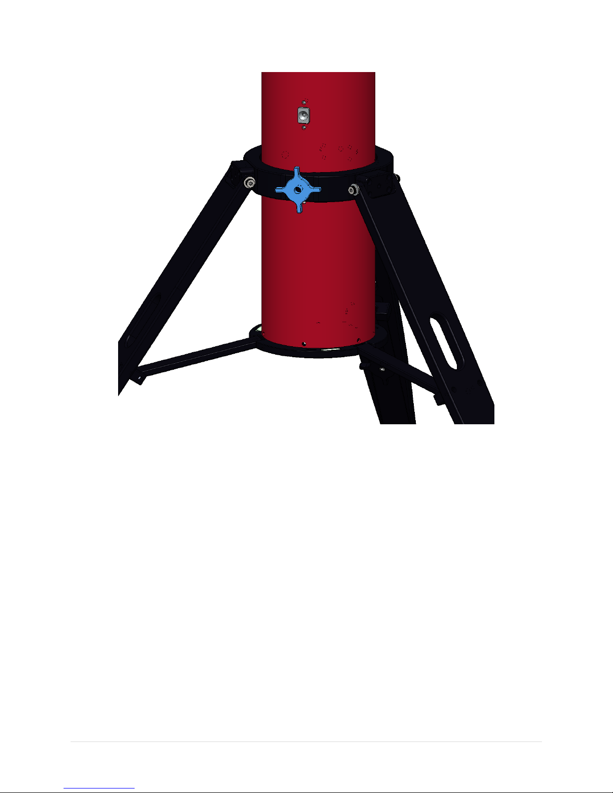
The tripod height position locking knob is located on the center ring that adjusts the height of the tripod
and can be seen in Figure 5. When this knob is unscrewed so the tip does not engage the stainless steel
detent, the center ring is free to slide up and down. By lifting up on the top plate the legs will expand
and slide between the different height positions.
Once the tripod legs are at the desired pier height, the knob must be tightened until it fully engages and
presses against the stainless-steel detent.
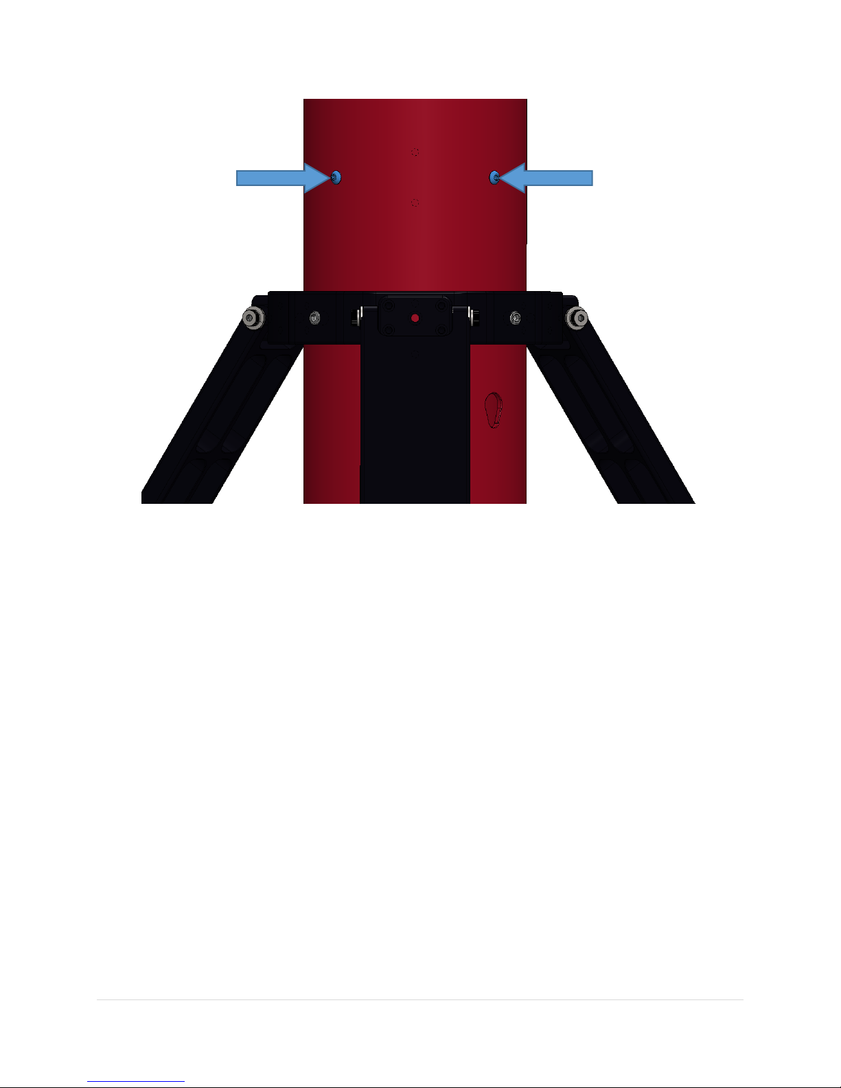
When the knob is screwed all the way in, there are two button heads on the opposite side of the tube
(Figure 6) as the position locking knob should and they should sit right on top of set screws in the center
ring (Figure 7). This ensures that the contact points are on stainless steel, resulting in less force exerted
on the aluminum tube. If the knob is fully tight, but the contact of the set screw is not quite right, see
“Button Head Adjustment” on page 11 on how to make this adjustment. (This should not need to be
adjusted frequently.)
5 | P a g e
Figure 5: Height position lock knob.
6 | P a g e
Figure 6: Button head contact points.

7 | P a g e
Figure 7: Button head and set screw contact.
Top Plate Adjustment
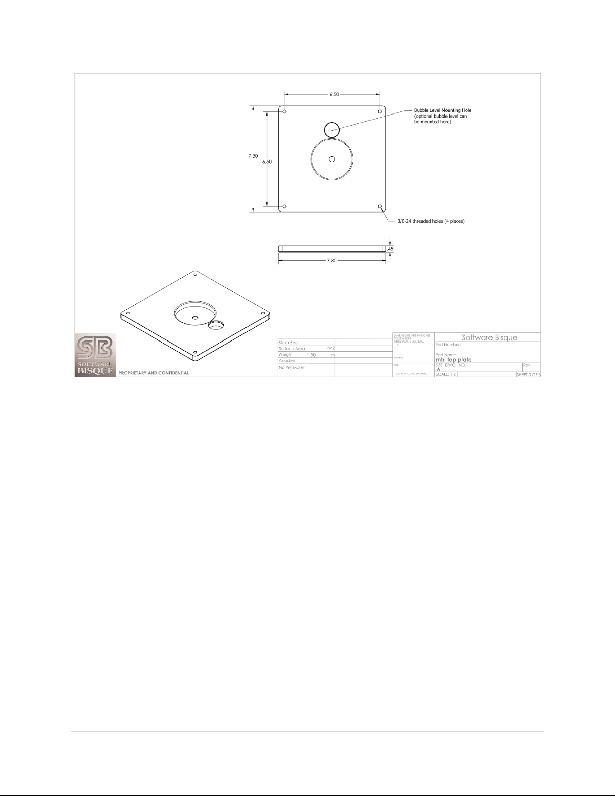
The top plate has dimensions of 7-¼ in (18.4 cm) as shown in the technical drawing in Figure 8. The top
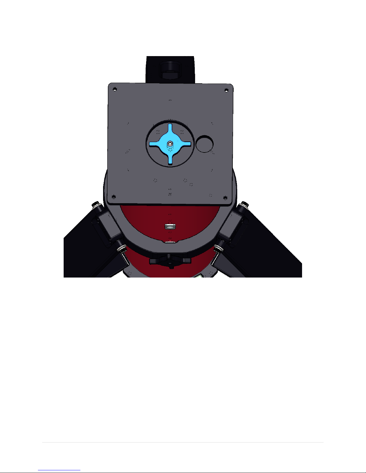
plate can also rotate 360° to assist in polar alignment. The knob located on the top plate (Figure 9)
loosens and secures down the top plate from rotating.
This adjustment should be done before mounting the Paramount MYT on the tripod. It is
good practice to tighten this knob all the way down when you have the approximate
location however the top plate can be rotated with a bit of force after the Paramount MYT is
attached. The tighter the knob after this adjustment, the less room for movement there will
be during use.
8 | P a g e
Figure 8: Top plate technical drawing.
9 | P a g e
Figure 9: Top plate and knob.
Leveling the MYT Tripod
There are three bubble level plus arrow pairs machined in to the bottom ring of the tripod (Figure 10).
Each arrow points to the leg that changes the level of this bubble; see the examples highlighted in blue
in Figure 11.
Use these three levels to get your tripod as level as possible before mounting the Paramount MYT. The
circular depression in the top plate is a mounting hole for an optional bubble level (sold separately).
While the three bubble levels that are integrated into the legs should provide the means to achieve level
exceptionally well, the optional level bubble, when installed, can also be used to help level the tripod.

10 | P a g e
Figure 10: Leveling arrows and level bubbles.

11 | P a g e
Figure 11: The blue arrow points to the leg to raise or lower for this level bubble.
Button Head Adjustment
The Paramount MYT Tripod has been designed to ensure there are stainless steel on stainless steel
contact points. These contact points are on the opposite side of the tripod as the ring locking knob as
shown in Figure 12. There is a minor adjustment that can be done to ensure they are contacting in the
correct spot. (Again, this adjustment is not something you should have to do often.)
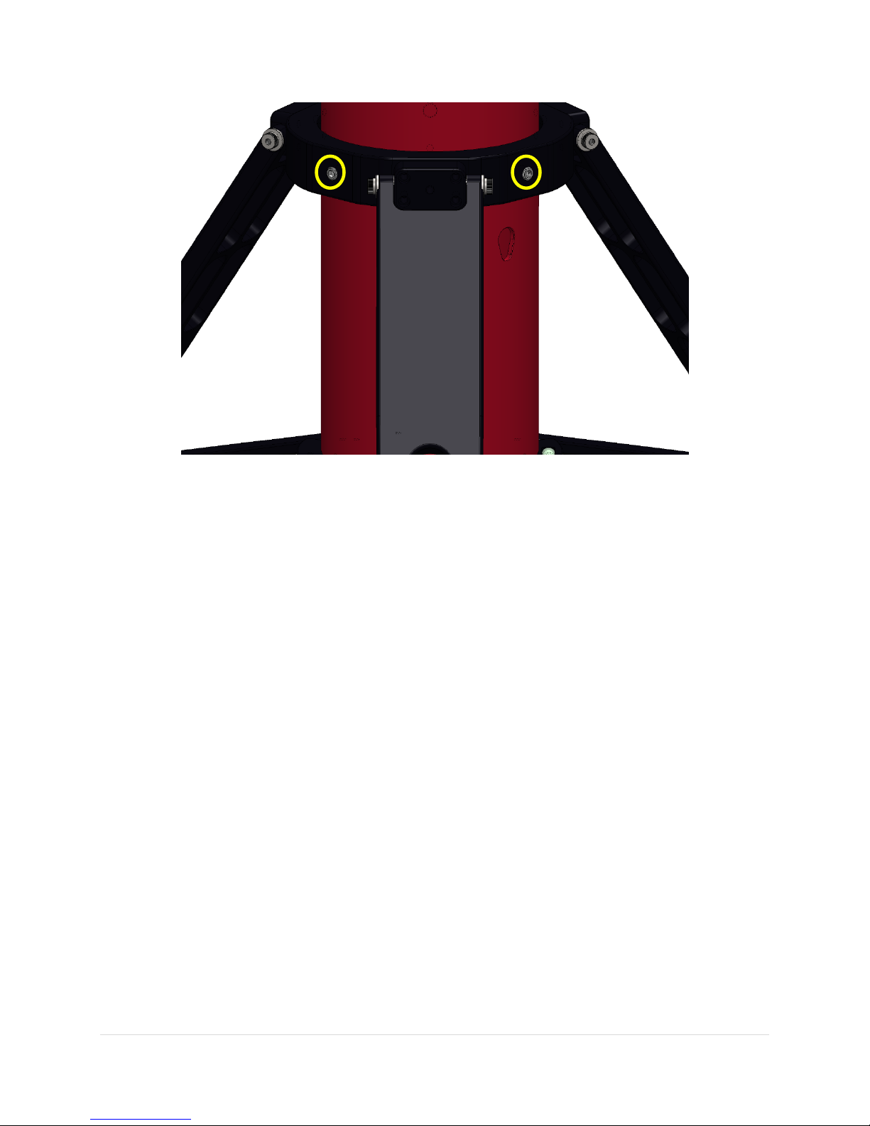
12 | P a g e
Figure 12: Stainless steel set screws circled in yellow
There are two 3/8-24 set screws stacked on each other in each of the two contact spots. The set screw
closest to the center tube you can look at from above the tripod and should be able to see it touching
the top of the button head cap screw (BHCP) as shown in Figure 13. The one stacked behind the first set
screw is there to prevent the first from moving or coming unscrewed.
The only time you should need to adjust these screws are when the locking knob is screwed all the way
in and the BHCPs are not sufficiently contacting the set screws.
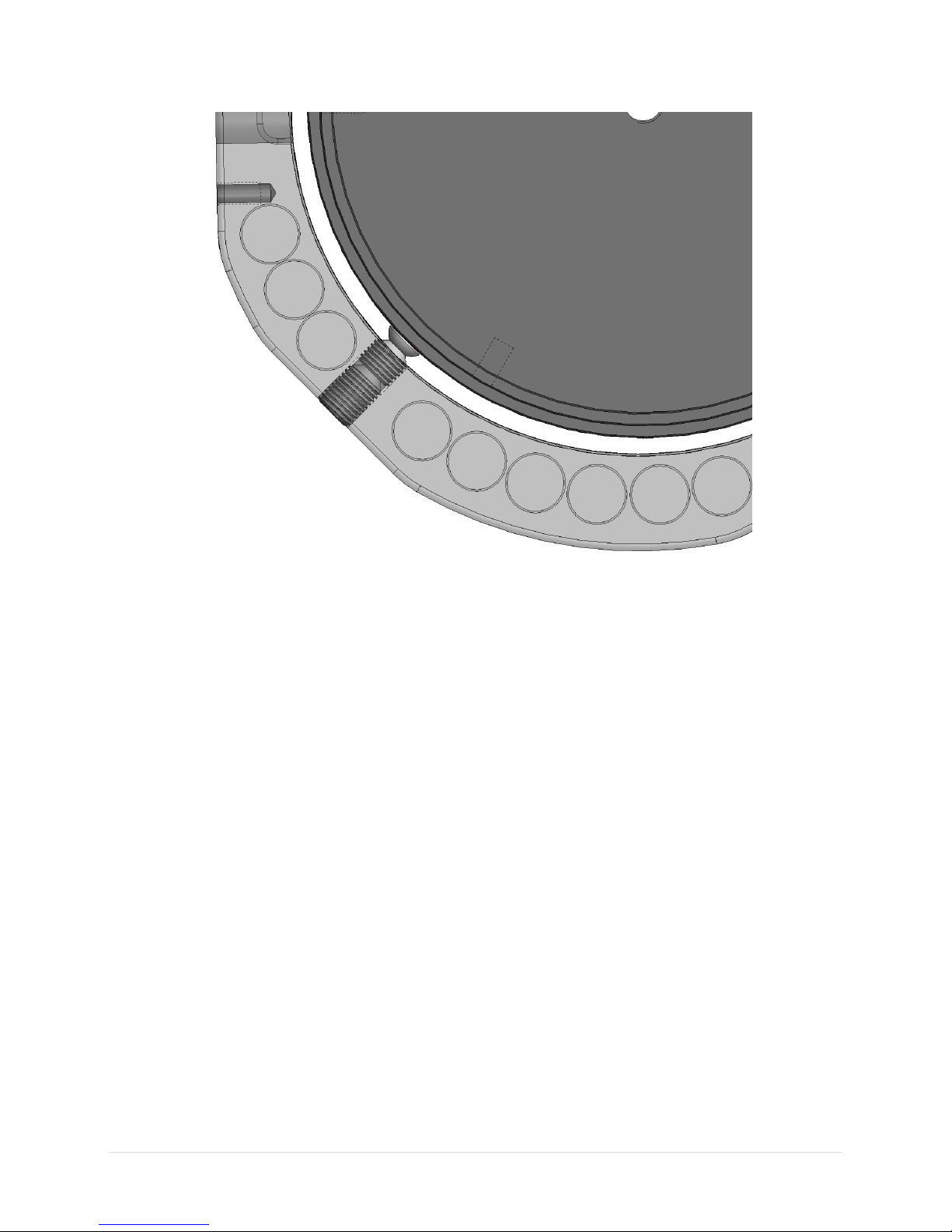
13 | P a g e
Figure 13: Set screws in transparent ring
Optional Extension Tube Accessory
To accommodate longer optical tubes, a 10-inch extension tube can be added to the top plate. A longer
tripod carrying case to accommodate the extension can also be purchased from the Software Bisque
Store.
The extension tube installation kit comes with the extension tube, an extension tube connector, and
eighteen 10-32x5/16-inch BHCPs (the eighteen include a few extra).
Installation Instructions
Remove the MYT Tripod’s top plate from the MYT Tripod by unscrewing and removing the knob then top
plate see Figure 14.

14 | P a g e
Figure 14: Remove top plate.
Using and 1/8-inch hex wrench, remove six 10-32 x 1/2-inch BHCPs that hold on the top mounting plate.
Use a broom handle or something similar from the opposite end of the tube to help push the mounting
plate out (Figure 15).

15 | P a g e
Figure 15: Remove top attach plate.
Place the extension tube attachment on the original tripod tube and replace the six 10-32x1/2-inch
BHCS (button head cap screws) taken out (Figure 16).
Figure 16: Mount and secure extension tube attachment.

16 | P a g e
Add the extension tube onto the extension tube attachment that was just mounted and screw in six new
screws to attach, see Figure 17.
Figure 17: Mount and secure extension tube.
Re-attach the top mounting plate to the top of the extension tube and attach with six 10-32 x 1/2-inch
BHCSs (Figure 18).
Figure 18: Re-attach and secure top mounting plate.

17 | P a g e
Replace the tripod’s top plate and use the knob to secure it to the top of the cylindrical tripod base
(Figure 19).
Figure 19: Replace top plate and knob.
Check to ensure all screws are tight and the MYT Tripod is ready for use.
Appendix A: User Guide Revision History
Revision Number
Changes
1.3
•Clarified optional bubble level on the top plate.
1.2
•Added extension tube instructions
1.1
•Added Table of Contents.
•Added page numbers.
•Minor formatting corrections.

18 | P a g e
Revision Number
Changes
1.0
•Initial Publication.
Table of contents
Other Software Bisque Camera Accessories manuals


