Software Bisque Pyramid Portable Pier User manual

Pyramid Portable Pier™
User Guide
Revision 2.5 May 2018
© 2018 Software Bisque, Inc.

Page 3 of 19
Introduction
The Pyramid Portable Pier is a lightweight and extremely stable platform designed to directly
accept various telescope mounts (adaptor plates for the Paramount MX and Paramount ME
mounts are available). Designed to shoulder up to 113 kg (250 lb.), the Pyramid Portable Pier
has many innovative features:
•Extremely lightweight at 9 kg (20 lb.) with unsurpassed stability
•Portable design that allows the legs to be quickly expanded or collapsed for easy setup
•360-degree azimuth adjustment makes polar alignment simpler
•Coarse level adjusters for observing on slopes up to six degrees
•Ergonomic fine leveling adjusters minimize back strain during setup
•Built-in bubble level for coarse leveling (10 arcminutes per one-tenth inch accuracy)
•Integrated center tray for holding small items
These features produce a portable imaging platform that can be quickly setup, leveled and
aligned with the celestial pole while providing unmatched stability.
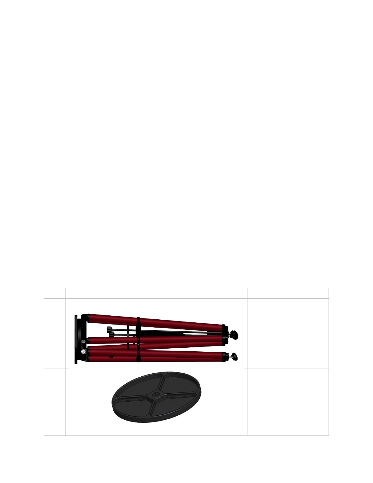
Packing List
The Pyramid Portable Pier is shipped in a single box that includes the following components.
Qty.
Photo
Description
1
Tripod assembly with
top plate(s) for the
Paramount ME or the
Paramount MX.
1
Center dish/tray.
5
Delrin washers

Page 4 of 19
Qty.
Photo
Description
1
3/8–24 x 2½-inch bolt
1
3/8–24 Acorn nut
2
Clamp nut (upper and
lower; upper remains in
place during shipping).
1
3/16-inch wrench for
coarse adjust clamp
screw. See “Coarse
Leveling”on page 13.
Optional Accessories
Extension tube(s). See
“Optional Accessories”
on page 18.
Bolt rod and nuts for
mounting the extension
tube. See “Optional
Accessories”on page 18.

Page 5 of 19
Pyramid Pier Parts
Figure 1: Pyramid Portable Pier components.
Pier Assembly
The tripod arms that hold the center dish in place are disassembled to prevent damage during
shipping. There are currently two versions of the tripod arm assemblies: tripods shipped before
July 2013 and tripods shipped on or after July 2013. Both versions require a one-time arm
assembly, which is critical for normal tripod operation and use.
To assemble the tripod arms, you need:
•One center dish
•Five (5) Delrin washers for tripods shipped before July 2013 or four (4) Delrin washers
on tripods shipped after July 2013
•One (1) 3/8–24 x 2½-inch bolt
•One (1) 3/8–24-inch acorn nut
•One lower clamp nut

Page 6 of 19
The legs of the tripod should be spread out to place the tripod arms in the correct position for
assembly.
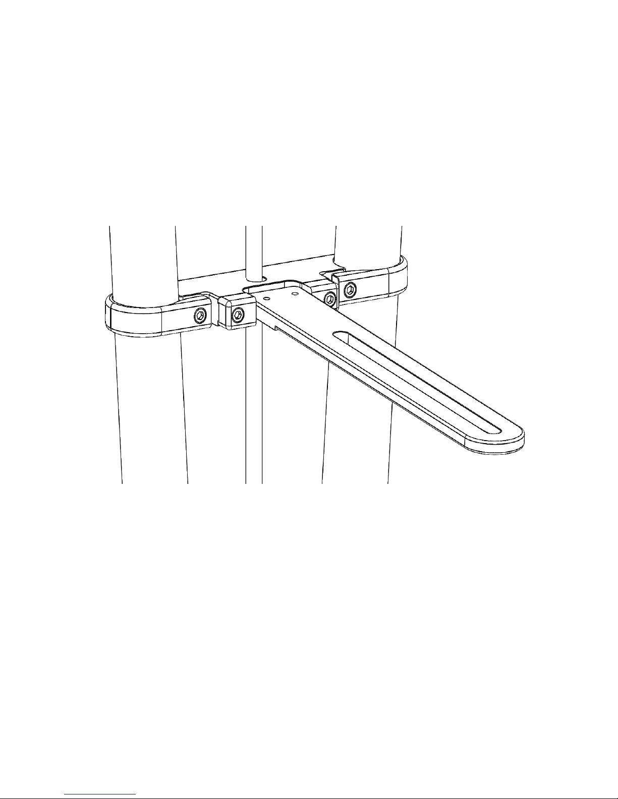
Tripods shipped in or before July 2013 are assembled as follows:
The tripod arms must be assembled in the correct order!
Each tripod arm is permanently mounted to one of the tripod legs in a different
vertical mounting position (top, middle, or bottom; see
Figure 2). The arm that is mounted to the tripod leg at the top position
must be placed at the topmost position where the arms intersect. The
arm that is mounted to the tripod leg at the bottom position must also be
on the bottom where the arms intersect. The arm mounted to the tripod
leg in the middle position must be placed in the middle.
If the tripod arms are not assembled in the correct order, the centers of
the arms will not align properly.
Figure 2: Tripod (before July 2013) arm mounted in the middle position.
Figure 5 shows the order to assemble each component.
Note that each tripod arm is mounted to the tripod leg at a different vertical position: top, middle and
bottom. In
Page 7 of 19
Figure 2, the arm is in the middle position. When assembling the arms, make sure to “stack”
them in the same order as they are mounted. The arm mounted in the top pin must be placed
nearest the center dish, followed by the middle arm and then the bottom arm. If the arms are
placed in a different order, the center of the arms will not be properly aligned, and the legs will
not expand or collapse properly.
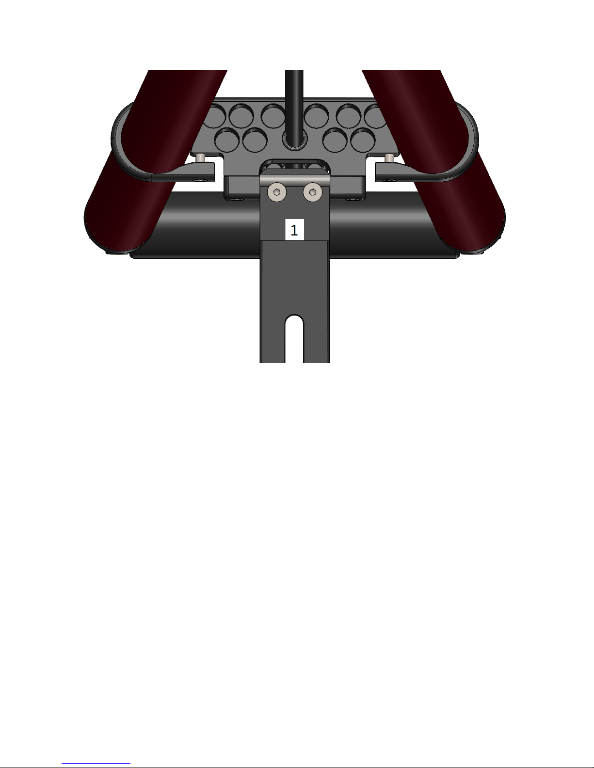
Tripods shipped after July 2013 are assembled as follows:
Figure 3: Tripod after July 2013 arm assembly.
Page 8 of 19
Figure 4: Sticker or etching placement to help with initial assembly.
Page 9 of 19
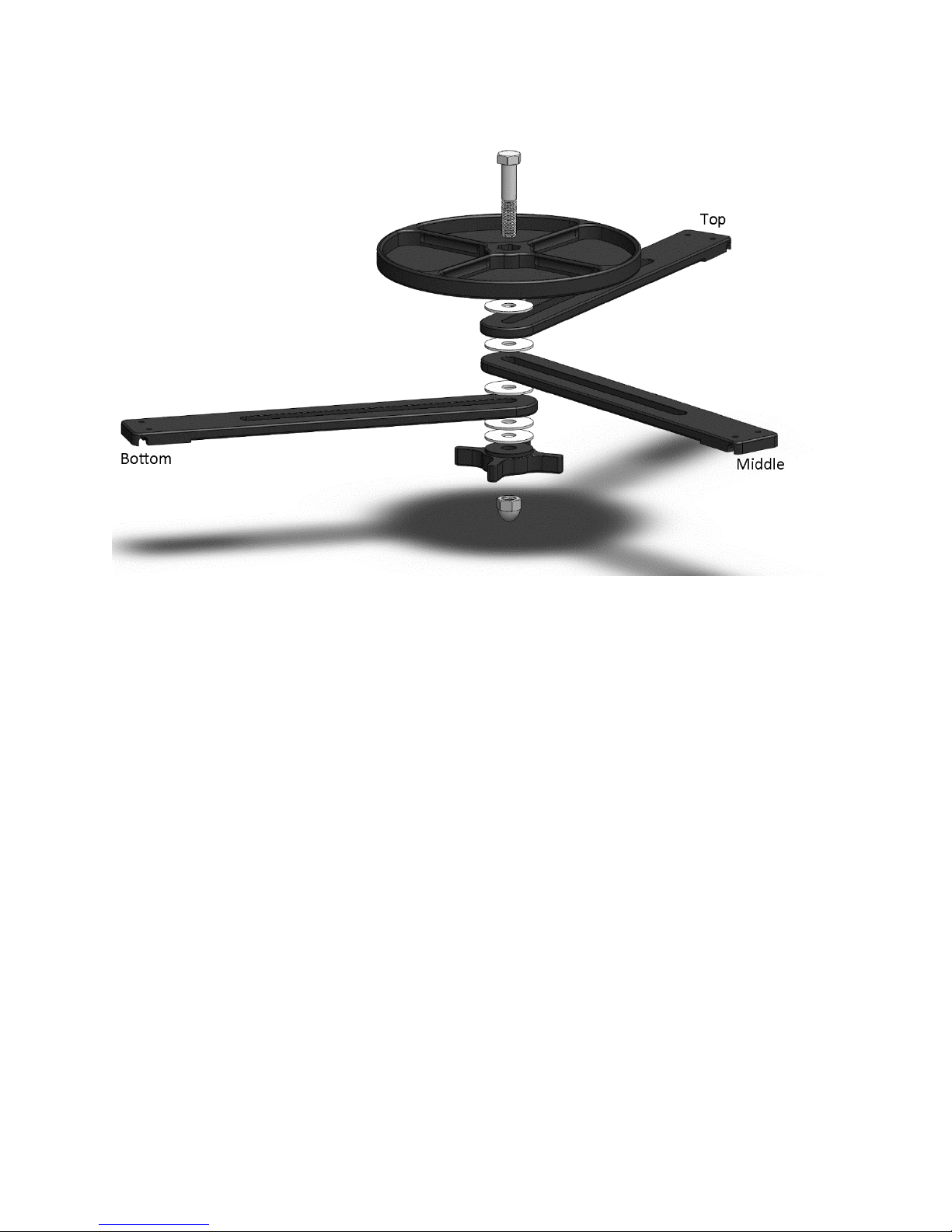
Figure 5: Tripod arm assembly: top (1), middle (2) and bottom (3). *
*Tripods shipped after July 2013 required one washer to be installed between the bottom arm
and knob.
Page 10 of 19
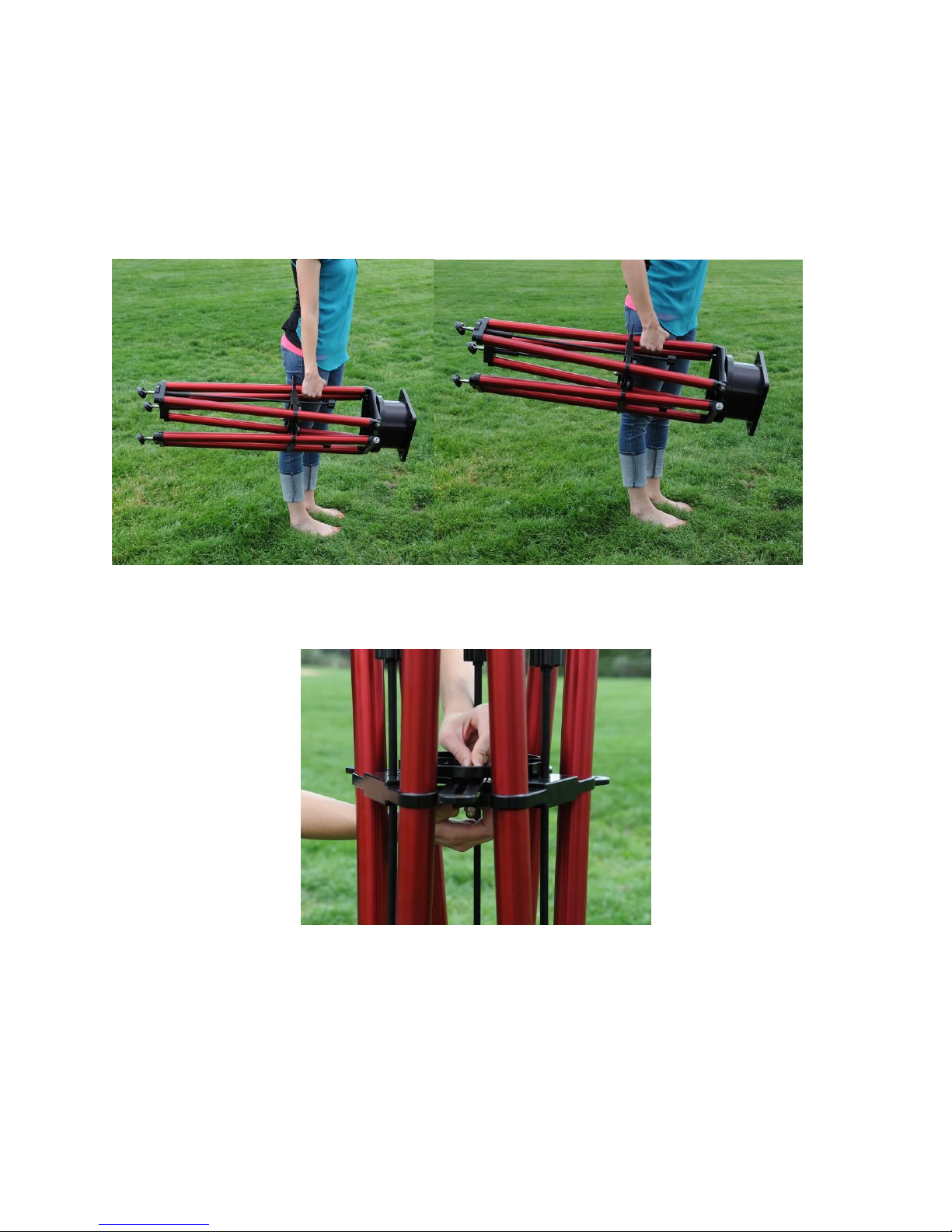
Transporting the Pier
Before picking up or transporting the tripod, make sure the lower clamp nut is tight, so the legs
stay in position. Otherwise, moving the portable pier is simple and can be carried by any of the
legs (Figure 6).
Figure 6: Carrying the Pyramid Portable Pier.
Expanding the Pier Legs
Figure 7: Loosen the clamp nut before expanding the legs.
1. Ensure the lower clamp nut is completely loose so that it is stopped by the acorn nut
(Figure 7).
Page 11 of 19
Figure 8: Extending the pier legs.
2. Place one pier leg on the ground and use both two hands to simultaneously pull out the
other two legs. You can also pull out one leg at a time, provided each leg is extended
about 1/3 of the way at a time.
Figure 9: Tripod legs fully extended.
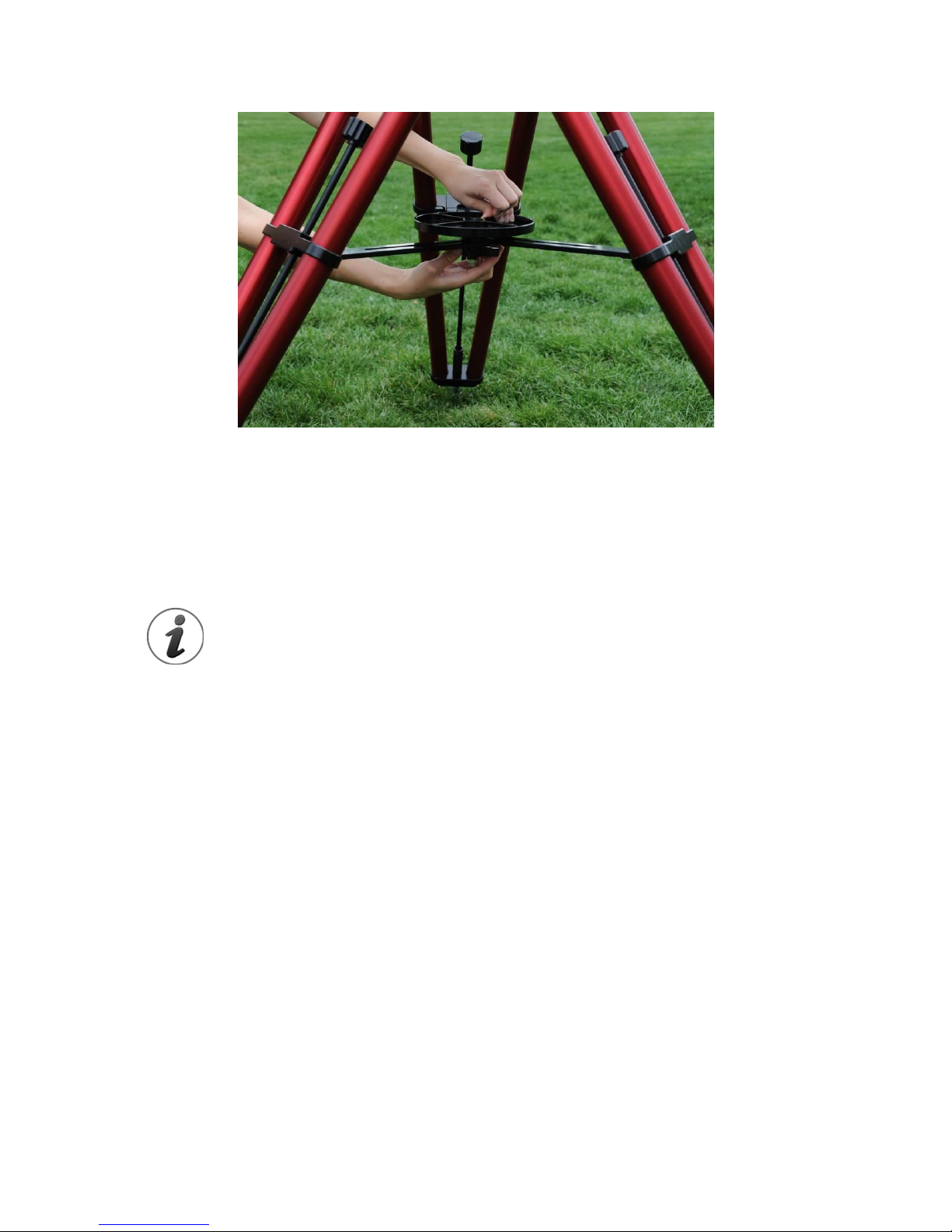
Page 12 of 19
Figure 10: Tightening the clamp nut.
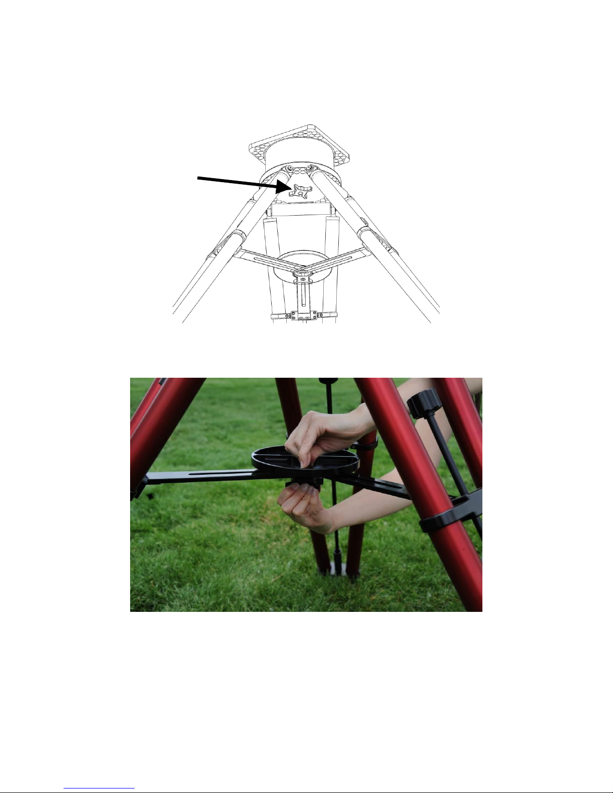
When the legs are fully extended (Figure 9), the arms must be parallel to the ground. Once the
legs are in the fully-extended position, tighten the clamp nut to compress the three arms
between the center dish and the clamp nut itself (Figure 10). You can rotate the center dish
clockwise to perform the last bit of tightening as it provides a convenient surface to grasp.
During normal use, always fully extend the pier legs.
•Leveling the top plate must be done using the coarse and fine
levelers, not by partially expanding the legs.
•The tripod is in the most stable position when all three the legs are
fully extended, and the clamp nut is tight.
Leveling the Top Plate
There are several benefits from leveling the top plate before placing the mount on top of the
Pyramid Portable Pier, including:
•Doing so ensures that the load is stable once the mount and other equipment are
added.
•When altitude and azimuth adjustments are made during polar alignment, a level tripod
insures the adjustments to one axis do not change or pollute the other axis.
•If you frequently observe at the same remote location, after the mount is leveled and
aligned with the celestial pole the first time, mark the altitude of the polar axis using a
piece of tape so that it can be restored later. On subsequent visits to the site, carefully
level the mount, then place the altitude of the polar axis on the mark. From here, polar
alignment can be accomplished by rotating the azimuth axis, only.

Page 13 of 19
Make sure to get the tripod very close to level before placing the mount on the top plate.
Though you can make leveling adjustments with equipment on the tripod, it is much easier
when there is not any additional weight.
Also note that the leveling adjustments change the footpad location; the foot moves outward
when lowering and inward when raising a given leg. Therefore, it is good perform a rough level,
then push down or sit on the tripod, then level again. This process helps ensure the feet are
firmly seated on the ground.
Figure 11: Coarse and fine leveling components near the pier’s foot.
Note: The thin line machined into the fine leveler shows the center of travel. To ensure
maximum travel in each direction, the fine leveling adjusters should be centered by turning the
fine leveling knob until this line is coincident with the bottom of the coarse leveler.
Coarse Leveling
At the end of each leg is a coarse adjuster that provides several inches of adjustment. If the
ground is close to level and does not require more than about 0.75-inches (18 mm) of
adjustment, then the coarse levelers do not have to be used. Otherwise, use a 3/16-inch hex
Page 14 of 19
wrench to loosen the coarse adjust clamp screw and make leveling adjustments. Once
loosened, position the coarse adjuster to get close to level, then tighten coarse adjust clamp
screw. Notice the coarse adjuster has a specially machined “rough”surface to achieve
maximum friction when clamped.
Fine Leveling
The fine leveling is accomplished using the three fine-leveling knobs (
Figure 1). The placement of these knobs allows you adjust level while simultaneously watching
the level bubble located on the top plate. Once the bubble is located inside the black ring,
pushing down on the top plate with all your weight or sit on it to get the feet firmly seated on
the ground, then check level again.
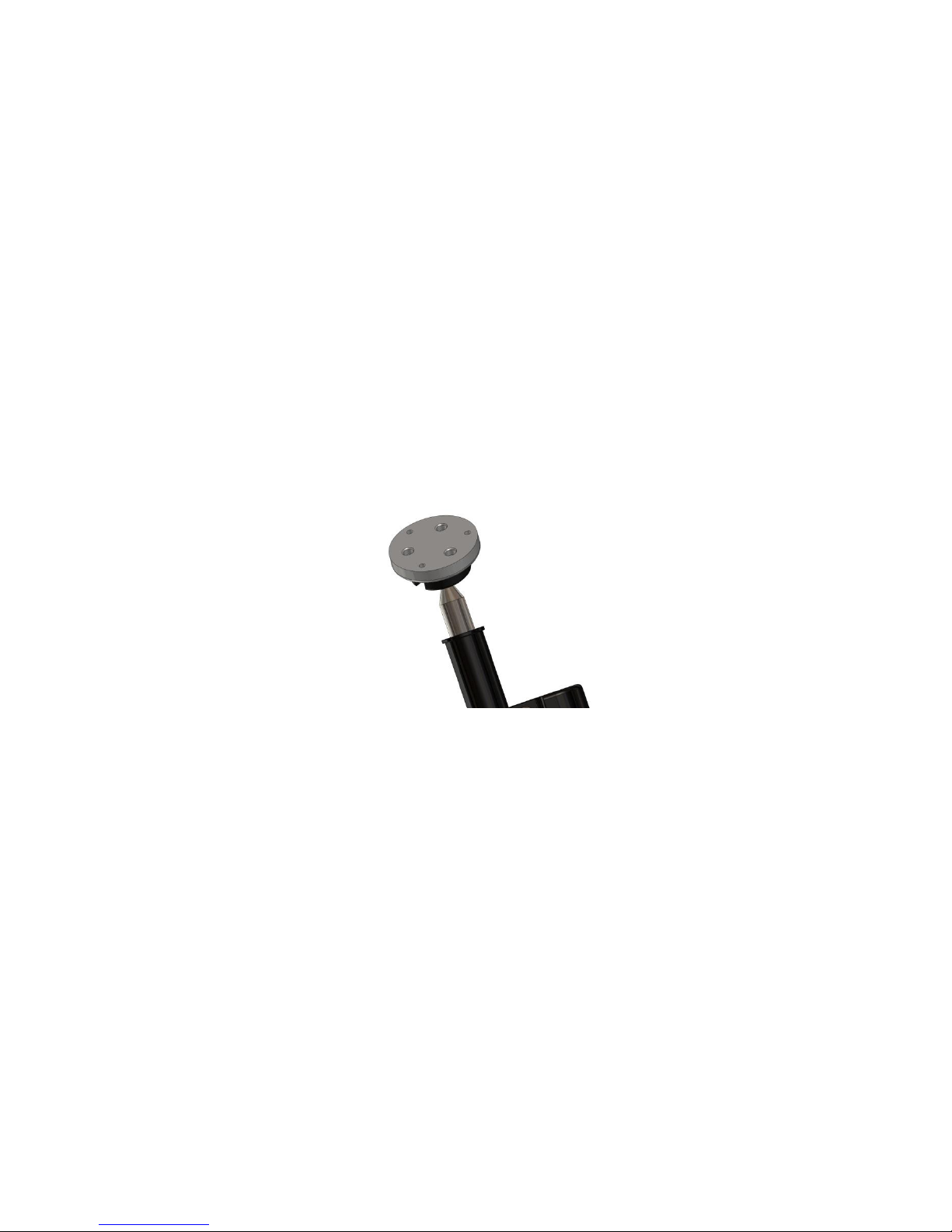
Tripod Feet
Figure 12: Tapped holes in pier foot*.
There are three tapped holes in the bottom of each tripod foot that accept an 8-32 socket head
cap screw. These can be added to provide some grip or traction on compliant surfaces, such as
grass.
* On mounts shipped after July 2017, he diameter of the circular tripod foot was increased for
added traction and stability.
Page 15 of 19
Figure 13: Top plate with integrated bubble level.

Page 16 of 19
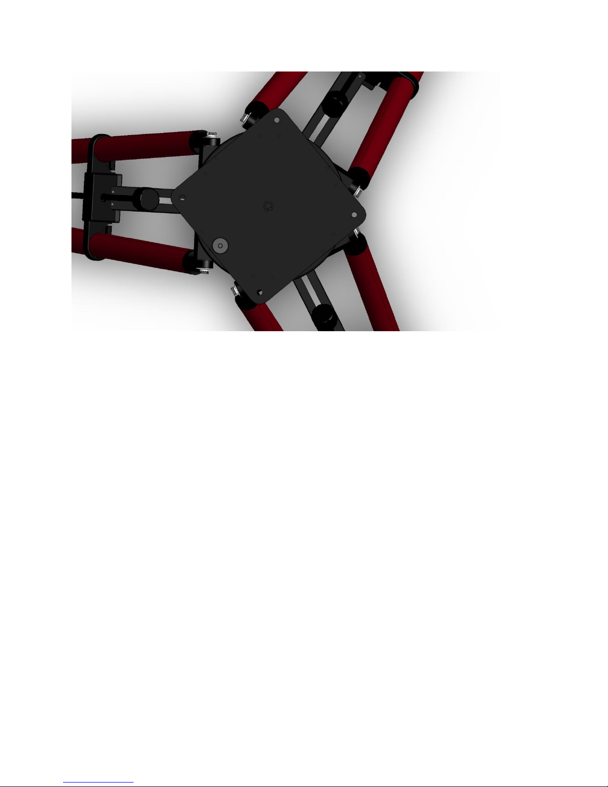
Rotating the Top Plate
The ME II/MX Pyramid Portable Pier top plate has tapped holes to accept both the Paramount
ME II and Paramount MX/MX+. On the ME II/MX Pyramid Portable Pier, the Paramount
MX/MX+ can be mounted in two positions; in the center of the rotating top plate or offset so
the edge of the base plate on the Paramount MX/MX+ meets one edge of the Pyramid Portable
Pier’s rotating top plate (see Figure 15).
Note: On Pyramid Portable Piers shipped before January 2018, to mount a Paramount MYT or a
Paramount MX to the Pyramid Portable Pier top plate, a Paramount MX Pier to Paramount MYT
Adaptor Plate is needed.
Figure 14: The MX/MYT Tripod top (on Pyramid Piers shipped after January 2018).
Figure 15: The Paramount ME II/MX Tripod top plate.
Once the top plate is level, you can adjust the mount’s position in azimuth by loosening the
clamp nut beneath the two plates and rotating the top plate. When loose, the top plate can be
rotated indefinitely.
Page 17 of 19
At lower latitudes, it is best to have one of the legs pointing towards the celestial pole as the
center of mass of the payload tends to be near the edge of the top plate. Once mount is at the
correct azimuth, tighten up the clamp nut again and you should be ready to use your mount.
Figure 16: The arrow shows the clamp nut that must be loosened before rotating the top plate.
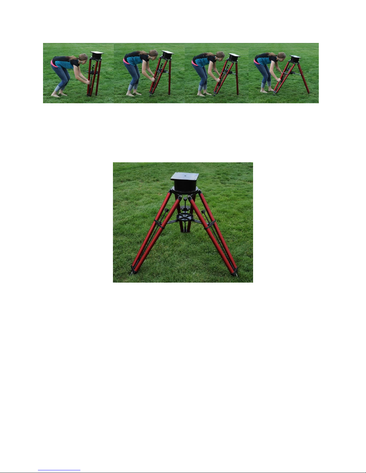
Collapsing the Legs
Figure 17: Loosen the clamp nut before collapsing the legs.
Unscrew the lower clamp-nut all the way until it is stopped by the acorn nut.
Page 18 of 19
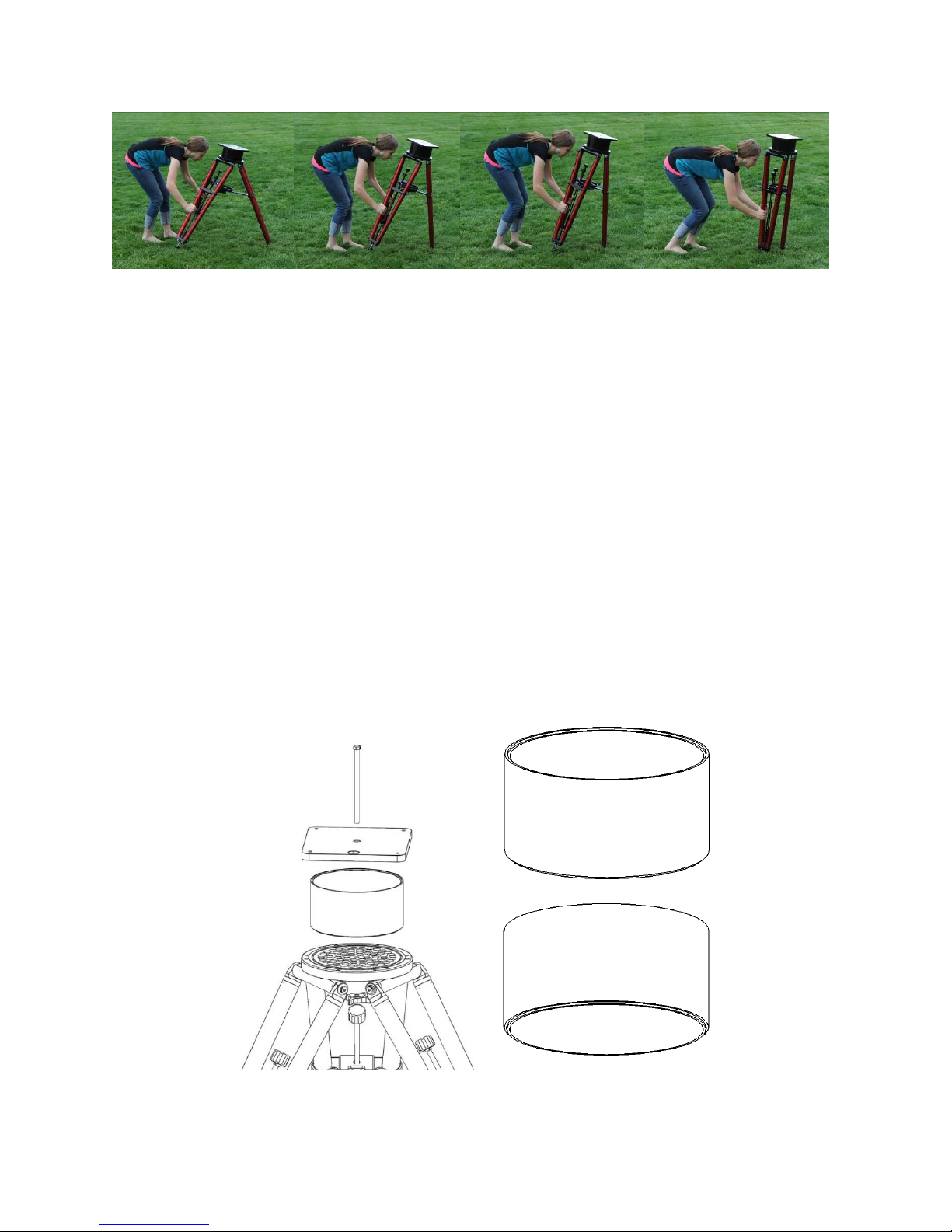
Figure 18: Photo sequence showing how to collapse the legs.
Next, grab two of the legs and lift them up and towards yourself, then with the remaining leg
still touching the ground, push the two legs you are holding towards the leg contacting the
ground to collapse all legs simultaneously. Once collapsed, tighten the clamp nut just enough
to hold the legs in place.
Optional Accessories
Extension Tubes
To accommodate longer optical tubes, one or more extension tubes can be added to the top
plate. Extension tubes can be added between the round and square plates on the top of the
pier.
The extension tubes are available in four inch, and six-inch heights, allowing for total heights of
4, 6, 8, 10, 12, 14, etc. by stacking various combinations. Note that each different height
requires a matching length 3/8-24 threads-per-inch bolt or bolt rod, plus 2.5 inches. For
example, a four-inch extension tube requires a 6.5-inch bolt or bolt rod.
Figure 19: Mounting extension tubes.

Page 19 of 19
Adding Extension Tubes
1. Remove the acorn nut from the end of the bolt under the circular top plate (this allows
the clamp nut to be removed)
2. Fully remove the clamp nut from under the circular top plate. The rectangular top plate
is now free.
3. Remove the rectangular top plate by lifting it upwards.
4. Place the extension tube or tubes between the circular and rectangular top plates,
making sure that they are inserted correctly. The male end should be downward and
will fit into the circular top plate.
5. Insert the longer bolt through the stack of rectangular top plate, extension tube and
circular top plate.
6. Add the white Delrin washer then screw on the upper clamp nut followed by the acorn
nut.
7. Firmly hand-tighten the upper clamp nut.
Figure 20: Pyramid Portable Pier with extension tube.
Table of contents
Other Software Bisque Camera Accessories manuals


