SOGEDIS DT2T Series User manual

$!#"!$ DT2T
(#),#'"# &#%'$!#
2
1. Specifications
1.1. Product Specifications
60 LT 60 LT 61 LT
BLDC
61 LT
TOUCH
61 LT
TOUCH
BLDC
62 LT
BLDC
62 LT
TOUCH
BLDC
62 LT
TOUCH
BLDC
Product Type Front Loader
Max W as Load Capacity 7 kg 8 kg 9 kg 9 kg 9 kg 9 kg 10 kg 10 kg
Max Dry Load Capacity 5 kg 6 kg
Max Spin Speed (r/min) 1400 rpm
Control Panel LED display
W ash Programs 15 settings
Dimensions
Height 84,5 cm
W idth 59,7 cm
Depth 58,2 cm
Other Features Child Lock
Delay Time
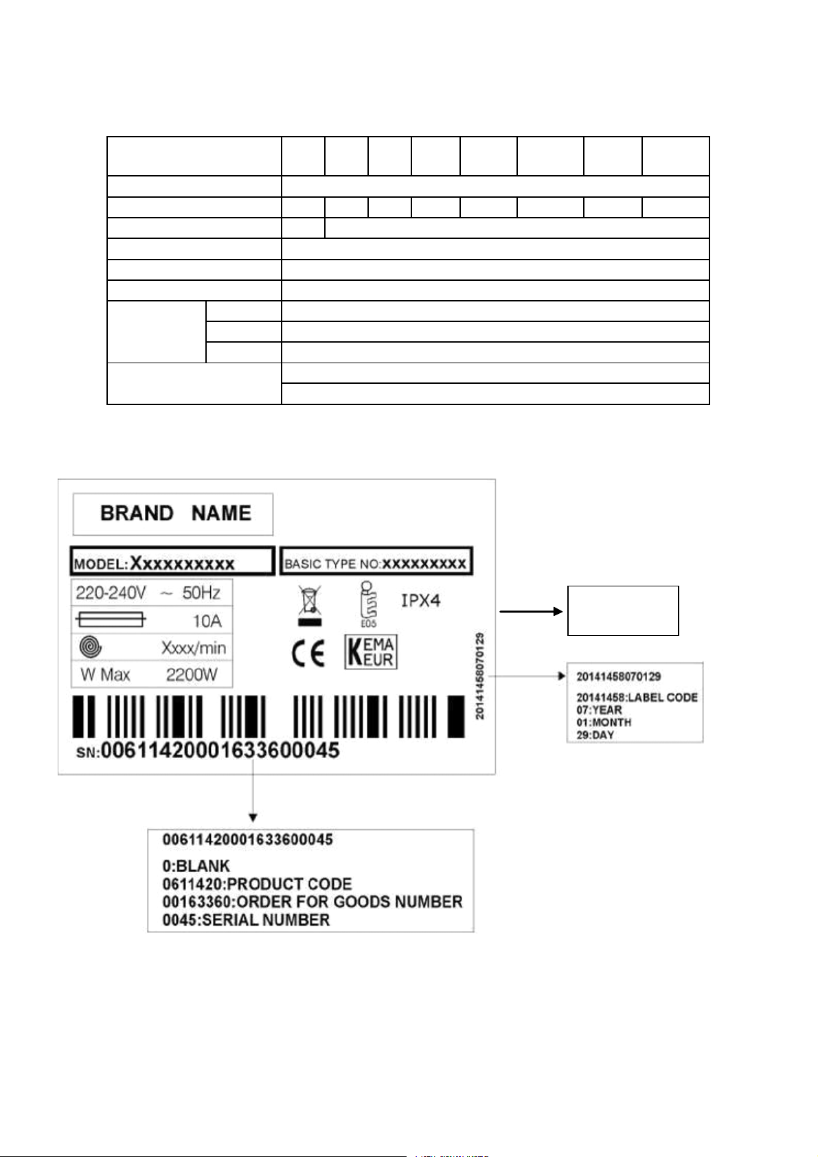
1.2. Name Plate
0000
SERVICE INDEX
NUMBER
3
2. Installation Instructions
2.1. Moving and Installing
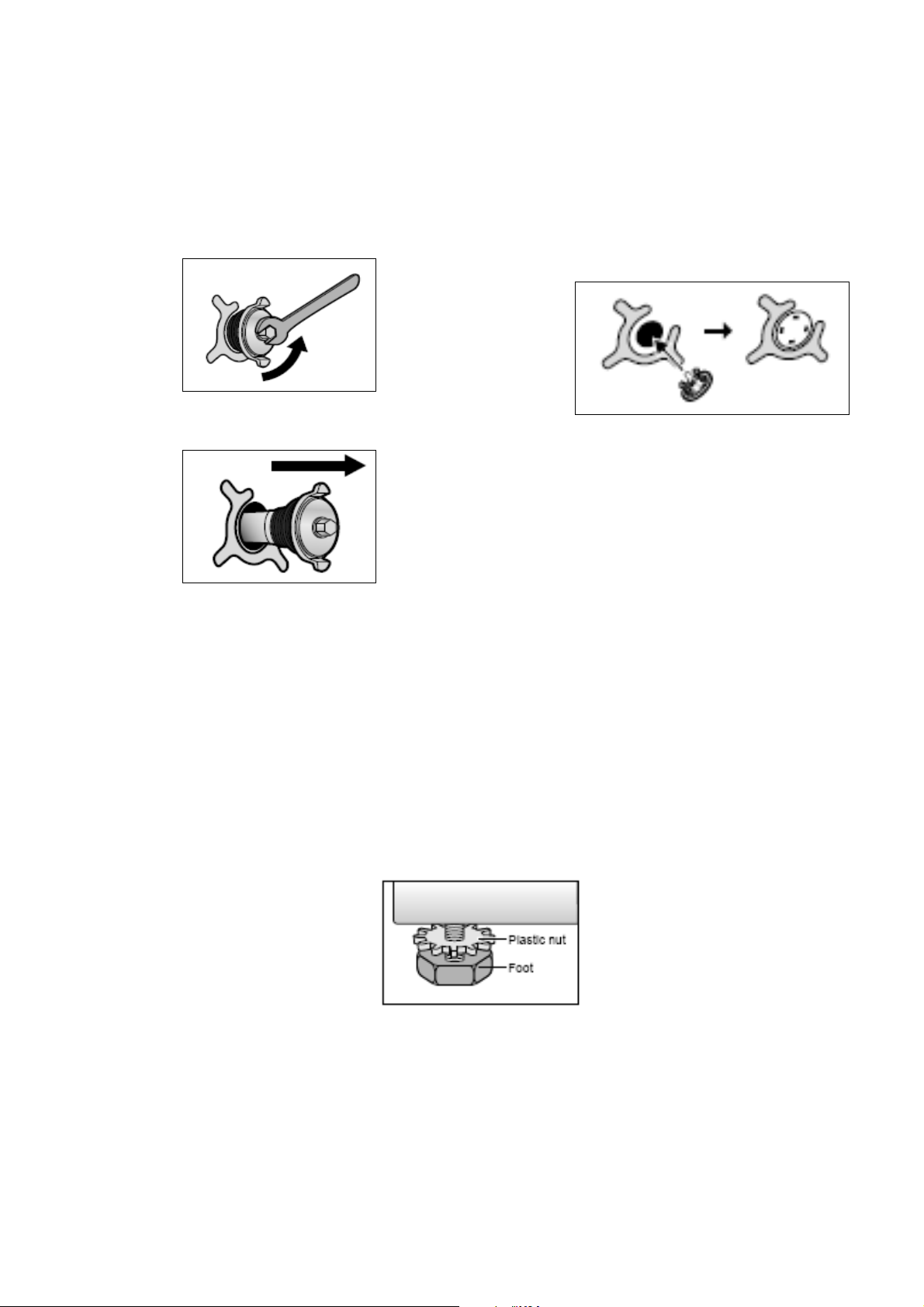
2.1.1. Removal of Transportation Screw
1. Transportation screws, which are located at the back
side of the machine, must be removed before running
the machine.
2. Loosen the screws by turning them anticlockwise with a
suitable spanner.
3. Pull out the screws and rubber washers.
2.1.2. Foot Adjustment
1. Do not install machine on rugs or similar surfaces.
2. For machine to work silently and without any vibration, it
should be installed on a flat, non-slippery firm surface.
Any suspended floor must be suitably strengthened.
3. You can adjust the level of machine using its feet.
4. First, loosen the plastic adjustment nut away from the
cabinet base.
2.1.3. Electrical Connection
1. W ashing machine requires a 50Hz supply of 220-
240Volts.
2. A special earthed plug has been attached to the supply
cord of washing machine. This plug must be fitted to an
earthed socket. The fuse value fitted to this plug should
be 13 amps. If you have any doubts about electrical
supply, consult a qualified electrician.
4. The holes where the transport screws have been
removed should be covered with the plastic transport
caps found in the accessories bag.
5. The transportation screws that have been removed from
the machine must be re-used in any future transporting
of the machine.
5. Change the level by adjusting the feet upwards or
downwards.
6. After level has been reached, tighten the plastic
adjustment nut again by rotating it upwards
against the base of the cabinet.
7. Never put cartons, wooden blocks or similar
materials under the machine to balance
irregularities of the floor.
THIS APPLIANCE MUST BE EARTHED.
?\`S_a aVS [OQVW\Shs plug to a grounded
socket which you can easily reach.
4
2.1.4. Water Supply Connection
1. W ashing machine is supplied with a single (cold) water
inlet.
2. To prevent leakage from the connection joints, a rubber
washer is included in the hose packing. Fit this washer
at the end of water inlet hose on the tap side.
3. Connect the hose to the water inlet valve. Tighten the
plastic connector by hand. Please call a qualified
plumber if you are unsure about this.
4. W ater pressure of 0,1-1 MPa from tap will enable
machine to work more efficiently.(0,1 MPa pressure
means water flow of more than 8 litres in 1 minute from
a fully opened tap)
2.1.5. Drain Connection
1. Make sure that water inlet hoses are not folded, twisted,
crushed or stretched.
2. The drain hose should be mounted at a minimum height
of 60 cm, and a maximum height of 100 cm from the
floor.
2.2. Detergent Box Group
PREWASH = WATER ENTRY VALVE 1
MAIN = WATER ENTRY VALVE 2
SOFTENER = WATER ENTRY VALVE 1 + VALVE 2
5. After connection is complete, check for leakage by
turning on tap completely.
6. Make sure that water inlet hoses can not become folded,
damaged, stretched or crushed when the washing
machine is in its final position.
7. Mount the mWj[h _db[j ^ei[ je W |t j^h[WZ[Z mWj[h jWf,
3. The end of the drain hose can be connected directly to a
drainage stand-pipe or alternatively to a specific
connection point designed for that purpose on the waste
outlet of a sink unit.
4. Do not extend the drain hose or guarantee will be
invalidated.
MAIN
SOFTENER
PREWASH
VALVE1
VALVE2
5
3. Operating Instructions
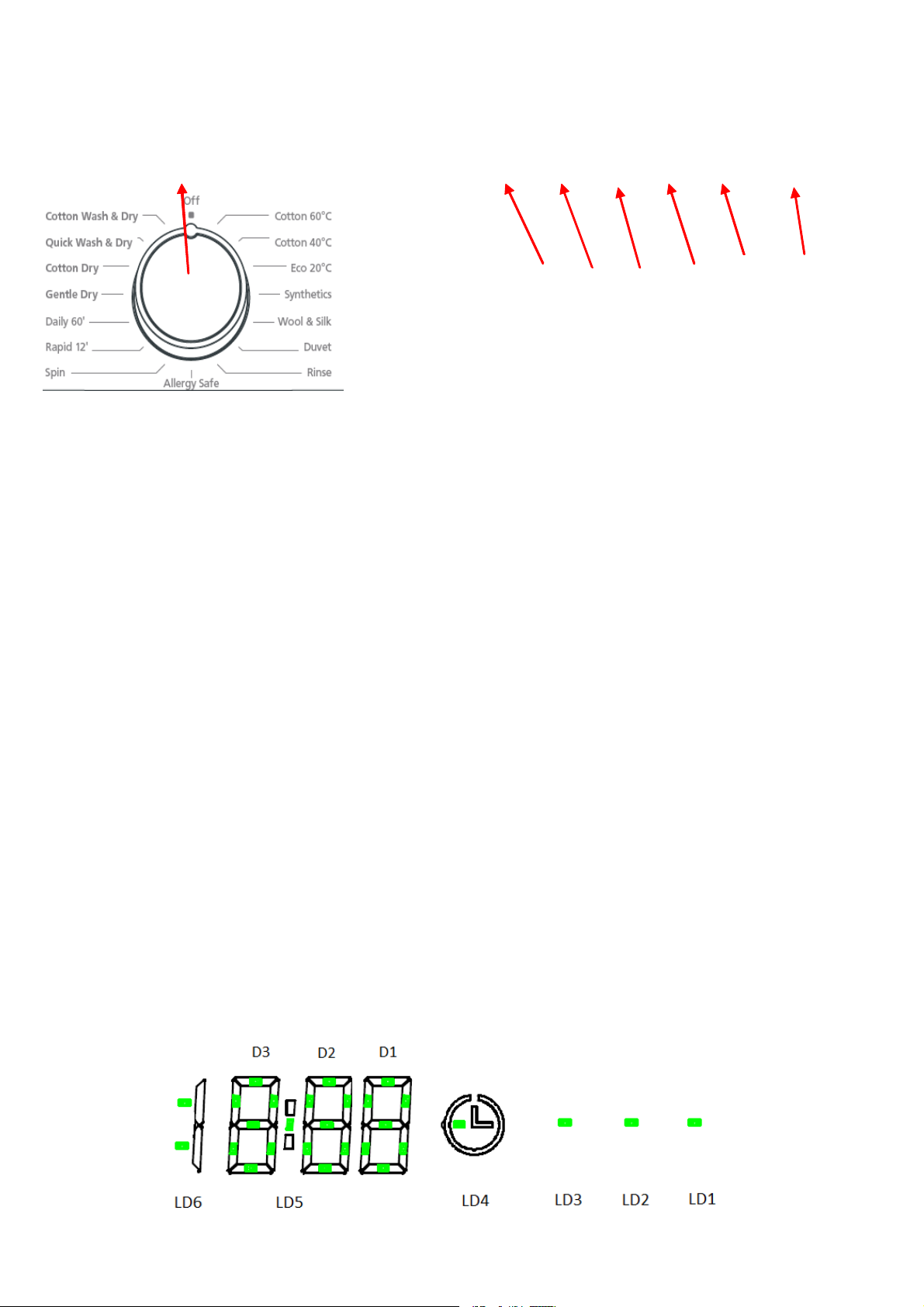
3.1. LCD Screen, Function Buttons & Knobs
T2 Touch Control Panel
T2 Mechanic Control Panel
T2 Rotated
PR
SW4
SW3
SW2
SW1
S
W5
SW6
6
3.2. Program List
**Rapid 15 is available for without twinjet model, Rapid
12 is available for with twinjet model.
PR Program Selector with ON/OFF
SW1 Start / Pause
SW2 Dry Option Selection
SW3 Time Dry Option Selection
SW4 Spin Speed Selection
SW5 Temperature Selection
SW6 Temperature Selection
LD1 Start/Pause Led
LD2 KG
LD3 Time Dry Option Led
LD4 Delay Timer Led
LD5 Double dot led
LD6 H[Z e\ s/t
LD7 gLD10 Options Led
LD11 - LD16 Spin Speed Led
LD17 - LD22 Temperature Led
LD23 - LD26 Time Dry Led
LD27 - LD30 Dry Option Led
LD31 - LD34 Eco Time Energy Leds
LD35 - LD38 Eco Time W ater Leds
LD39 Delay Timer Led
D3-D3 7-segment display
KNOB
POSITION PROGRAM
1 Cotton 60q?
2 Cotton 40q?
3 Eco 2.q?
4 Synthetics
5 W ool & Silk
6 Duvet
7 Rinse
8 Allergy Safe
9 Spin
10 NWf_Z /3%-/0u**
11 DW_bo BWij 4.% 4.q?
12 Gentle Dry
13 Cotton Dry
14 Quick W ash & D ry
15 Cotton W as h & Dry
16 OFF

7
3.3.
Child Lock
Activation
1. Press the SW2 and SW3 buttons simultaneously for 3 sec.
Deactivation
1. Press the SW2 and SW3 buttons simulaneously for 3 sec
Activation
Deactivation
Child lock during selection:
Machine does not respond to any pressing of buttons or
changing position of program knob. CL at 7 segment display will
make fast blink for 2 sec to
indicate child lock is activated.
Child lock during the program:
Machine does not respond to any pressing of buttons or
Y^Wd]_d] fei_j_ed e\ fhe]hWc adeX, s?Ht is visualized on display for
2 sec to indicate child lock activation with tone D buzzer in models
^Wl_d] Xkpp[h efj_ed, =\j[h 0 i[Y s?Ht _dZ_YWj_ed _\ \_n[Z e\\ WdZ
remaining time is visualized on display.
In end condition
W hen cycle is finished child lock is automatically
deactivated. It is not possible to activate child lock during End mode.
In Error M ode
Child lock will be automatically deactivated when error is
detected
Child lock during delay mode:
Child lock can be activated / deactivated during delay
mode. If child lock is active during delay mode, it will be kept locked
until the end of washing (unless user deactivates by pressing SW2
and SW3 buttons simultaneously for 3 sec.)

8
4. Test Mode
4.1. Autotest
4.1.1. Touch Button M odel Version
* This test is for quick checking of the product. You can not see the failure codes.
1. Set program knob at position 3
2. Push SW 4 button
3. Keeping SW4 button pushed, turn program knob to position 2
4. After 3 sec, door will be locked and machine enters autotest mode.
5. Release SW4 button.
6. s=Q# m_bb X[ l_ikWb_p[Z ed H?@,
4.1.1. Mechanic Button Model Version
* This test is for quick checking of the product. You can not see the failure codes.
1. Push SW4 button. Keeping SW4 button pushed, turn program knob to position 1.
2. After 3 sec, door will be locked and machine enters autotest mode. Release SW4 button. "AU" will be visualized on LCD.

9
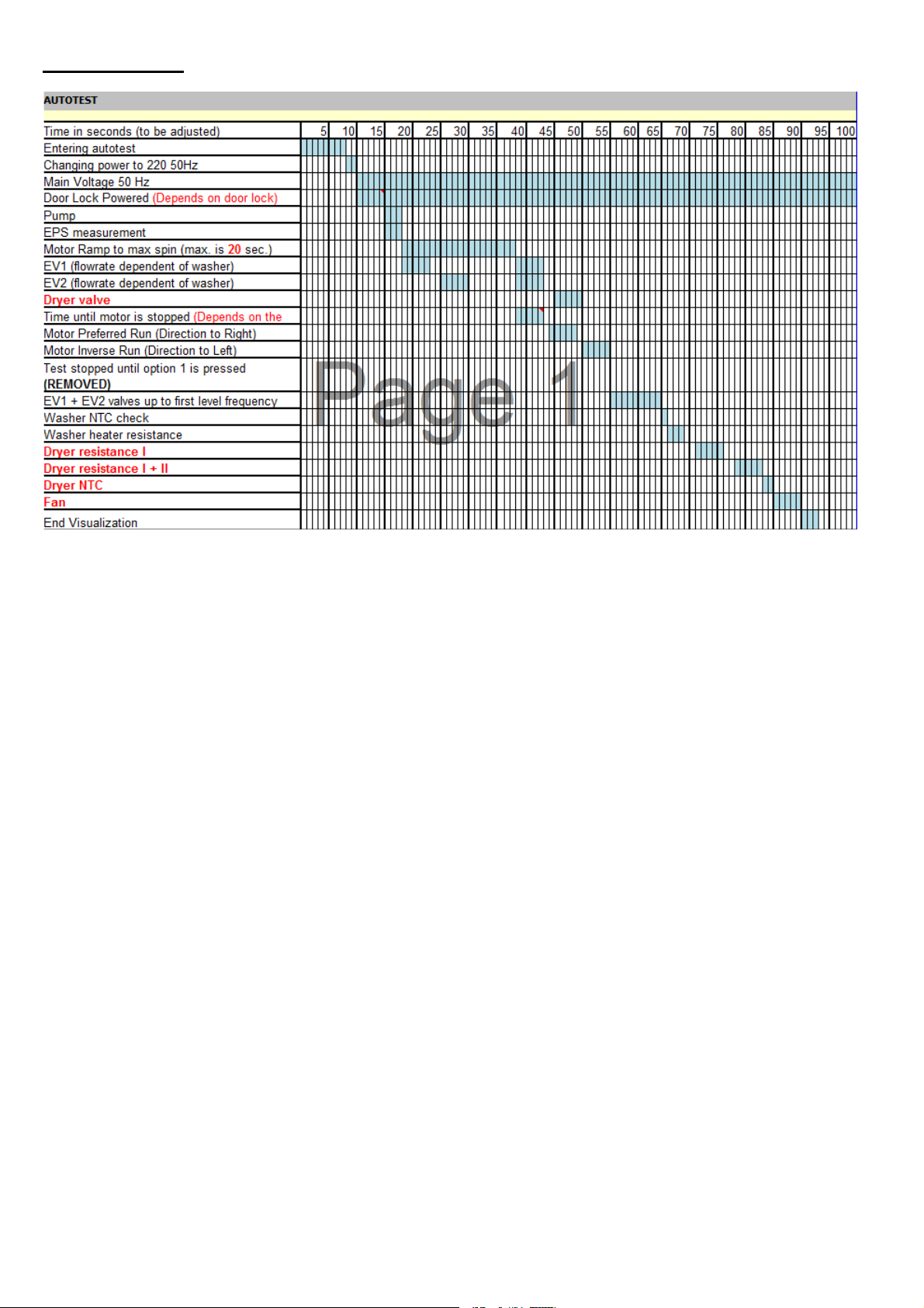
The test steps are as below;
Step1: The pump is activated for 3 seconds (if pump connettor is disconnected it should shows pump error screen (E03) on
display) and there is EPS check , the frequency value should be between the 46.04 Hz and 43.40 Hz. It checks the EPS and
if it is OK it continues the autotest; if it is NOK then it should give E10 ERROR & cancels the autotest ( goes to the selection
mode ). Also if any frequency can not be detected, then it means there is problem with connecion or EPS, so it gives E10
which is EPS error and cancels the autotest.
Step2: The motor ramps to max spin for 20 seconds. While its speed rising up to the maximum speed the EV1 (prewash
valve) is activated for 5 seconds and then the EV2 (wash valve) is activated for 5 seconds.
Step3: The motor reduces speed to stop (depends on the motor stop time) for 5 seconds. While it is slowing down it
activates EV1 and EV2 valve, concurrently.
Step4: The motor turns to right. Also, dryer valve is activated between sec46-50 for 5 sec.
Step5: The motor turns to left for 5 seconds.
Step6: Twin Jet will be activated for 3 sec ( For twinjet models only)
Step7: The EV1 and EV2 are activated concurrently until it reaches pressure sensor's first level frequency (Hz) for 5
seconds.
Step8: Oe\jmWh[ m_bb Z[j[Yj JP?%i h[i_ijWdY[ lWbk[ WdZ m_bb Y^[Ya _\ j^[ j[cf[hWjkh[ _i X[jm[[d 3q? ; PZ[j[Yj[Z ; 2.q? , E\
it is inside the range, heating step will be done. If temperature value is outside the range, then it means NTC is detecting the
temperature in a wrong way and heating step will be skipped. Additionally if NTC connector disconnected it should shows
NTC failure code(E05) on display.
Step9: Software will detect NTC's resiijWdY[ lWbk[ WdZ m_bb Y^[Ya _\ j^[ j[cf[hWjkh[ _i X[jm[[d .q? ; PZ[j[Yj[Z ; 3.q? , E\
it is inside the range, autotest continues. If temperature value is outside the range, then it means NTC is detecting the
temperature in a wrong way , autotest is canceled and error is released. (E18)
Step10: Dryer resistance I and I&II are checked for 5sec in each.
Step11: Dryer NTC is checked for 2sec.
Step12: Fan is activated for 5 sec.
Autotest ends and "End" screen is visualized.

10
11
Without TJ models;

12
5. Service Mode
5.1. Service Autotest
End users can only see E1-E2-E3-E4. During service autotest, other failures can be seen.
1. To activate servic e autotest mode in touch models, set program knob at position 3, push SW3 button.
2. Keeping SW3 button pushed, turn program knob to position 2.
3. After 3 sec, door will be locked, and machine enters service autotest mode. Release SW3 button.
5.1.1. Mechanic Button M odel Version
1. To activate service autotest, Press SW 3 button and simultaneously position program knob to 1.
2. After 3 sec, door will be locked, and machine enters service autotest mode. Release SW 3 button.
In T0 "SA" will be visualized on LCD. In rest of the models "SAU" will be visualized on LCD.

13
The test steps are as below ;
Step1: O[b[Yjeh fei_j_ed / m_bb X[ smWi^[h ^[Wj[h edt
Before heating it should take water till first level frequency then start heating.
D[Wj[h m_bb X[ ed cWn, 6 c_dkj[i, =\j[h 6 c_dkj[i _\ j^[ j[cf, @e[id%j Y^Wd][ ceh[ j^Wd 0r?* _j m_bb h[b[Wi[ djY \W_bkh[, & A05 ).
Or if the ntc connection is broken then it should give again E05 ntc failure. At the end of heating, "sau" visualization should
make slow blink to indicate that the step is over.
*During this step if eps detects high water level, overflow algorithm is applied and e04 is released.
Note : if user changes the selector position, machine will do what is defined for the new selected position.
Step2: O[b[Yjeh fei_j_ed 0 m_bb X[ sfkcf edt
P[cf[hWjkh[ m_bb X[ c[Wikh[Z* _\ _j _i ^_]^[h j^Wd 3.qY* _j i^ekbZ jWa[ 6.i[Y, ?eeb_d] mWj[h * WdZ j^[d cWa[ #ZhW_d) 3i[Y,' Ef
pump error is detected e03 will be released.
At the end of pump activation, "sau" visualization should make slow blink to indicate that the step is over.
Step 3: Selector position 3 will be "dryer heater 1 & fan on "
At the beginning of the step, dryer ntc should detect and record the temperature.
Dryer heator 1 and fan should be activated for 3 min. At the end of 3 min dryer ntc should again detect the temperature, if
~j; /.qY* _j m_bb h[b[Wi[ [/2 \W_bkh[,
E\ ~j (!10'c, "sau" visualization should make slow blink to indicate that the step is over.
Step 4: Selector position 4 will be "dryer heater 2 & fan on "
At the beginning of the step, dryer ntc should detect and record the temperature.
Dryer heator 2 and fan should be activated for 3 min. At the end of 3 min dryer ntc should again detect the temperature, if
~j; /.qY* _j m_bb h[b[Wi[ [/2 \W_bkh[,
E\ ~j (!10'c, "sau" visualization should make slow blink to indicate that the step is over.
Step 5: O[b[Yjeh fei_j_ed 3 m_bb X[ s hWf_Z /3% t
So machine will make exactly the same algorithm of rapid 15'.
So, time for selector position 5 is 12 minutes.
During rapid 15 program if eps detects high water level, overflow algorithm is applied and e04 is released.
Step 6: O[b[Yjeh fei_j_ed 4 m_bb X[ sZho_d] 3t ij[f,
Machine will make below algorithm;
So, time for selector position 6 is 5 minutes.
=j j^[ [dZ e\ Zho_d] 3* s[dZt _i l_ikWb_p[Z WdZ Zeeh _i kdbeYa[Z, @kh_d] jest pressing other buttons makes no change.
During service mode if any failure is detected error code is shown in 7 segement display.
At the end of drying the door will be unlocked and machine will go to end mode.
7-segment display 1, 2, 3 :

14

05;9 $(
5.2. Failure Codes
*Some of the error codes can not be seen based on changing the product types
Error Indication Error Number Indication For User Indication For Service
Yes/No Yes/N o
Door is not locked E01 Yes Yes
Door is unlocked during programme E01 Yes Yes
Lack of water E02 Yes Yes
Pump failure E03 Yes Yes
Overflow E04 Yes Yes
NTC or Heater Failure E05 No Yes
Motor Failure - 1 (Tachometer open-short circuit or motor
connector is disconnected) E06 N o Yes
Configuration Failure E07 No Yes
Motor Triac Failure E08 No Yes
Voltage Error E09 Yes Yes
Electronic Pressure Sensor E10 No Yes
Dryer Card Communication Error E11 No Yes
3D Communication Error E12 No Yes
LCD Communication Error E13 No No
Dryer Resistance Failure E14 No Yes
Twinjet Failure E15 No No
High Temperature Error E16 No Yes
Flowmeter Failure E17 No Yes
Dryer NTC Failure E18 No Yes
BLDC Failure E19 No Yes
Pyrojet Failure E20 No Yes
Detergent Dosage Pump Failure E21 No Yes
Softener Dosage Pump Failure E22 No Yes
Communication Failure Between PCB and BLDC Card E23 No Yes
Wrong LCD Software E50 No Yes
Wrong BLDC Software E51 No Yes

05;9 $)
6. Troubleshooting Guide
All repairs which must be done on the machine should be done by authorized agents only. When a repair is required for machine or you are unable to
eliminate the failure with the help of the information given below:
'Unplug the machine.
'Close the water tap.
FAILURE PROBABLE CAUSE METHODS OF ELIM INATION
Machine does not
operate.
It is unplugged. Insert the plug into the socket.
Fuse is defective. Change fuse.
Start / Pause button has not been
pressed. Press the start / pause button.
The program knob is in 0 (off)
status. Bring the program knob on the desired status.
The door is not shut properly. Shut the door properly. You should hear the
click.
Child lock is active. See page 9.
Machine does not
receive water.
W ater tap is closed. Open water tap.
The water inlet hose may be bent. Check the water inlet hose.
The water inlet hose is obstructed. Clean the filters of water inlet hose.
The water inlet filter is obstructed. Clean the valve inlet filters.
The door is not shut properly. Shut the door properly. You should hear the
click.
Machine is not
draining water.
The drain hose is obstructed or
bent. Check the drain hose.
The pump filter is obstructed. Clean the pump filter.
The clothes are not placed inside
the machine in a well-balanced
manner.
Spread the clothes inside the machine in an
orderly and well-balanced manner.
Machine is
vibrating.
The feet of machine are not
adjusted. Adjust the feet.
Transportation screws are not
removed. Remove transportation screws.
There is a small amount of clothes
in the device. It does not prevent operation of the machine.
Excessive amount of cl othes are
filled in the machine or the clothes
are not placed in a well-balanced
manner.
Do not exceed the recommended quantity of
clothes and spared clothes in the machine in a
well-balanced manner.
FAILURE PROBABLE CAUSE METHODS OF ELIM INATION
Excessive foam in
the detergent
drawer
Too much detergent has been
used.
Press the start/pause button. In order to stop
the foam, dilute one table-spoon of softener in
half liter of water and pour it in the detergent
drawer. Press the start/pause button after 5-10
minutes. Arrange the amount of the detergent
properly in the next washing process.
Wrong detergent has been used. Use only the detergents produced for full
automatic machines.
The washing result
is bad.
Laundry too dirty for the program
you have selected. Select a suitable program.
The amount of detergent used is
not sufficient.
Use more detergent according to the
detergent.
The washing result
is not good.
Clothes exceeding the maximum
capacity has been filled in machine.
Put the clothes in machine in a manner not to
exceed its maximum capacity.
W ater may b e hard. Use the amount of detergent according to the
declaration of the detergent producer.
Distribution of the clothes in
machine is not well-balanced.
Spread the clothes inside the machine in an
orderly and well-balanced manner.
The water is seen
in the drum during
washing.
No failure. The water is at the lower
part of the drum.
There are residues
of detergent on the
clothes.
The pieces of some detergents
which do not dissolve in water may
stick to clothes as white stains.
>o YWb_XhWj_d] cWY^_d[ \eh sN_di_d]t fhe]hWc*
make an additional rinsing or eliminate the
stains After drying with the help of a brush.
There are grey
stains on the
These stains may be caused by oil,
cream or ointment.
In the next washing operation, use the
maximum detergent amount declared by the

05;9 $*
clothes. detergent producer.
The spinning
process is not done
or starts with delay.
No failure. The unbalanced load
control works in that way.
The unbalanced load control system will try to
distribute clothes in a homogenous manner.
After clothes are distributed, passage to
spinning process will be realized. In the next
washing process, place clothes into the
machine in a well-balanced manner.

05;9 $+
7& 5CK=KKAF>EP =G@ 2KKAF>EP 7GKLJM?LCHGK
7
.1 Top Plate
( )
IT\^eT cf^ bRaTfb cWPc UXg cWT c^_)_[PcT Pc cWT QPRZ* HdbW cWT c^_)_[PcT QPRZ P]S _d[[ Xc d_*
7
.2 Door
( )
IT\^eT cf^ bRaTfb cWPc UXg cWT S^^a* %Qh dbX]V K.1
c^^[& Hd[[ cWT S^^a d_*
* +
IT\^eT bRaTfb cWPc UXg cWT S^^a Va^d_* Hdc cWT S^^a ^dcbXST _[PbcXR fXcW WT[_X]V
bRaTfSaXeTa*
T25

05;9 $,
, -
IT\^eT cWT S^^a X]bXST _[PbcXR* IT\^eT bXg bRaTfb cWPc UXg cWT S^^a WX]VT*
.% /%
IT\^eT cWT S^^a WP]S[T* IT\^eT cWT S^^a WP]S[T _X]*
7
.3 Spring Wire
( )
?Xabc aT\^eT cWT b_aX]V fXaT UXgX]V cWT cdQ QT[[^fb bTP[
Qh dbX]V cWT b\P[[ bXiT bRaTf SaXeTa* Hd[[ cWT cdQ QT[[^fb
bTP[*
IT\^eT cWT cdQ QT[[^fb bTP[)Q^Sh UXgX]V b_aX]V*
7
.4 Detergent Drawer
( )
@T]c[h _d[[ cWT STcTaVT]c SaPfTa* NWX[T _aTbbX]V bX_W^] R^eTa ZTT_ _d[[X]V SaPfTa c^
aT\^eT Xc*

05;9 %#
7
.5 Control Panel
&
Electronic Card
( )
IT\^eT cWT bRaTf fWXRW UXgTb cWT R^]ca^[ _P]T[ c^ cWT
Ua^]c _P]T[*
IT\^eT cf^ bRaTfb UXgX]V R^]ca^[ _P]T[*
* +
Hd[[ cWT R^]ca^[ _P]T[ ^dc IT[TPbT cWT RPQ[T Va^d_ Pb bW^f] X] cWT _XRcdaT*
, -
IT\^eT cWT RPQ[T Va^d_ Pb Xc Xb bW^f] X] cWT _XRcdaT* IT\^eT T[TRca^]XR RPaS R^eTa Pb Xc Xb bW^f] X] cWT
_XRcdaT Qh dbX]V b\P[[ bRaTf SaXeTa*
. /
IT\^eT cWT DXVWcVdXST R^eTa Qh _aTbbX]V cWT R[X_ cWPc
UXgTb Xc*
IT\^eT cWT [XVWcVdXST Qh _aTbbX]V cWT R[X_ cWPc UXgTb
Xc*
This manual suits for next models
6
Table of contents
Other SOGEDIS Dryer manuals


Popular Dryer manuals by other brands


Alliance Laundry Systems
Alliance Laundry Systems Dryer Tumblers Installation & operation manual

ADC
ADC ML-78 parts manual

Whirlpool
Whirlpool Gas dryer installation instructions

Miele
Miele PDR 910 EL Installations plan

Hotpoint
Hotpoint TCEM 80C Instruction booklet

Whirlpool
Whirlpool LE6880XS Use & care guide

Bosch
Bosch WTR87T82GB Installation and operating instructions

Bosch
Bosch Maxx WTL 6500 Instruction manual and installation instructions

Smeg
Smeg DHT71EIT-1 user manual

Maytag
Maytag SDE/G4000 user guide

MASTER KITCHEN
MASTER KITCHEN MKD FS608HP ED A++ owner's manual

Mitsubishi Electric
Mitsubishi Electric JT-S1AP-W-NA installation manual