SOGEDIS HP T2 User manual

TUMBLE DRYER
SERVICE MANUAL
HP T2 PANEL- A+++ (Inverter)

CONTENTS
1. OVERVIEW AND WORKING PRINCIPLE.............................................................................................4
1.2. Working Principle:....................................................................................................................4
2. TECHNICAL SPECIFICATIONS............................................................................................................5
3. INSTALLATION.................................................................................................................................5
3.1. Issues that should be informed to customer.............................................................................5
4. CONTROL PANEL AND PROGRAM SELECTION TABLE........................................................................6
4.1. Control Panel ...........................................................................................................................6
4.2.Program List..............................................................................................................................6
4.3. Children’s Safety ......................................................................................................................7
5. FAILURE MODES AND SERVICE AUTOTEST .......................................................................................8
5.1. Failure Modes and Warning Leds..............................................................................................8
5.2. Service Autotest Steps..............................................................................................................9
6. DISASSEMBLY................................................................................................................................12
6.1. Top Plate................................................................................................................................12
6.2. Control Panel .........................................................................................................................13
6.3. Inverter Card Box ...................................................................................................................16
6.3. Inverter Card Box ...................................................................................................................17
6.4. Electronic Card.......................................................................................................................18
6.5. Dısplay Card ...........................................................................................................................19
6.6. Side Panel ..............................................................................................................................20
6.7. Supply Cable ..........................................................................................................................22
6.8. Emi Filter................................................................................................................................23
6.9. Rear Cover .............................................................................................................................24
6.10.Pump ....................................................................................................................................25
6.11.Process Fan ...........................................................................................................................27
6.12. Rear Panel............................................................................................................................28
6.13.Rear Isolation Group .............................................................................................................30
6.14. Rear Bearing Group..............................................................................................................31
6.15.Water Tank Housing..............................................................................................................32
6.16.Drum.....................................................................................................................................33
6.18.Capacitors.............................................................................................................................35
6.19.Belt .......................................................................................................................................36
6.20. Humidity Sensor...................................................................................................................37

6.21. Door latch ............................................................................................................................38
6.21. Plinth ...................................................................................................................................39
6.22. Cooling Fan ..........................................................................................................................40
6.23. Plinth Cover..........................................................................................................................41
6.24. Door.....................................................................................................................................42
6.26. Drum Bearing Wheel ............................................................................................................43
6.27. Drumlight.............................................................................................................................44
6.27. Front Panel...........................................................................................................................45
6.29. Door NTC..............................................................................................................................46
6.30. Side Bracket .........................................................................................................................47
6.31. Front Shield..........................................................................................................................48
6.32.Front Isolation Foam .............................................................................................................49
6.33. Cable Group .........................................................................................................................50
7. 7. COMPONENT SPECIFICATIONS AND MEASUREMENTS ...............................................................52
7.1. Motor ....................................................................................................................................52
7.1.1. Motor Measurements .........................................................................................................53
7.2. Pump .....................................................................................................................................54
7.2.1 Pump Measurements ...........................................................................................................55
7.3. Electronic Card.......................................................................................................................56
7.4. Door/Compressor NTC Sensor................................................................................................56
7.4.1. Door NTC Sensor Measurements.........................................................................................57
7.5. Compressor............................................................................................................................57
7.5.1. Compressor Measurements ................................................................................................59
7.6. Door Latch .............................................................................................................................60
7.6.1 Door Latch Measurements ...................................................................................................60
7.7. Humidity Sensor.....................................................................................................................61
7.7.1 Humidity Sensor Measurements...........................................................................................61
7.8. Cooling Fan ............................................................................................................................62
7.8.1. Cooling Fan Measurements .................................................................................................63
7.9. Drumlight...............................................................................................................................63
8. TROUBLESHOOTING......................................................................................................................64

HP T2 PANEL
SERVICE MANUAL
1. OVERVIEW AND WORKING PRINCIPLE
1. Top Plate
2. Control Panel
3. Loading Door
4. Plinth
5. Plinth opening slot
6. Ventilation grills
7. Adjustable feet
8. Plinth cover
9. Type plate
10. Lint filter
11. Drawer Cover
1.2. Working Principle:
In the heat pump dryer machine, heated air is sent to the wet laundry in the drum from the
heater side of the coil which called by condenser. The humidity of the laundry is taken and
reaches the cold side of the coil which called by evaporator via filter. With a compressor,
refrigerant is passed through inside of the tubes of coils both condenser and evaporator. A
capillary causes resistance against to refrigerant flow. By this way, the evaporator surface is
cooled and condenser surface is heated. The hot and humid air from the drum is reached cold
evaporator surface and the humidity on it is left as water. The condensing water in the
evaporator is pumped to the water tank by the pump.

HP T2 PANEL
SERVICE MANUAL
2. TECHNICAL SPECIFICATIONS
Manufacturer
Vestel White Goods
Capacity (max)
7 kg (100LT)
8 kg / 9kg (112LT)
H x W x D
845x596x563 mm
845x596x609 mm
Net weight (with plastic door)
42,6 kg
44 kg
Net weight (with glass door)
45 kg
46,4 kg
Voltage
220-240V / 50 Hz
Working Temp.
+5°C -+35°C
Electrical Current (A)
10 A
Power
1000 W
3. INSTALLATION
3.1. Issues that should be informed to customer
1. Drying machine must be grounded.
2. Lint filter must be cleaned after each use
3. Water tank must be unloaded after each use
4. Even if the heat exchanger cleaning warning les is not on : clean the heat exchanger
after every 30 drying processes or once a month
5. The amount of laundry should be appropriate to program.
6. Use this product only for laundry with a label that indicates it is suitable for drying.
7. Children should not play with appliance.
8. This product contains environmental friendly but flammable R290 gas. Keep open
flame and fire sources away from the product.
9. Ventilation grills should not be closed.
10. The service life time of tumble dryer is 10 years.
11. Adjustable feet should not be removed.
12. There should not be lockable or sliding door in the installation area
13. Never spray or pour water onto the dryer to wash it. There is a risk of electric shock.
Please ensure that customer reads the user manual
1. Check the environmental conditions. (Voltage, current etc.)
2. Ensure that product is used correctly
3. If the system displays failure code, find the corresponding code in the failure code list
then act according to this.
4. Check the electronic connections

HP T2 PANEL
SERVICE MANUAL
4. CONTROL PANEL AND PROGRAM SELECTION TABLE
4.1. Control Panel
Display Symbols
4.2.Program List
KNOB
POSITION
PROGRAM
1
Cotton Extra Dry
2
Cotton Cupboard Dry
3
Cotton Iron Dry
4
Synthetics Cupboard Dry
5
Synthetics Iron Dry
6
Delicate
7
Time Drying
8
Baby Care
9
Duvet
10
Extra Silent
11
Mix
12
Wool
13
Refresh
14
Express 45’
15
Shirts 30’
16
OFF

HP T2 PANEL
SERVICE MANUAL
***The machine has humidity sensor that detects whether the laundry dry or not. At the
programs that work with humidity sensor laundry does not dry in fixed time. Duration is
constantly updates according to humidity data taking from laundry.
***Time Drying Program: Humidity sensor is deactivated. The program ends when the time is up,
without checking the humidity of the laundry.
***Express 45’/ Shirts 30 ‘: Humidity sensor is activated. The program time may extend, if the
customer use different laundry according to the load in the program description.
Express 45' : 1 kg of cotton shirts spun at high speed in the washing machine are dried in 45 minutes
Shirts 30' : 2 to 3 shirts are ready for to be ironed in 30 minutes.
***Delicate: This programme dries synthetics, such as shirts, t-shirts, blouses, at a lower
temperature compared to the cottons programme.
*** Refresh: Time drying option is selected from 10 minutes to 150 minutes without providing hot
air, refresh is done and bad odors can be eliminated.
4.3. Children’s Safety
There is a child lock option to avoid changes in the program
flow when keys are pressed during the program. To activate child lock,
press and hold “sw2” and “sw3” keys simultaneously for 3 seconds.
When the child lock is active, all keys will be deactivated. Child lock will
be deactivated automatically at the end of the program. When the
child lock is being activated/deactivated, “CL” will flash on the display
for 2 seconds and an audio warning will be heard.
Warning: when the product is running or the child lock is active, if you turn the program selection knob,
you will hear an audible warning. Even if you set the program knob to another program, the previous
program will continue running. To select a new program, you need to deactivate the child lock and
then set the program selection knob to “Cancel” position. Then, you can select and start the desired
program.
HP T2 PANEL
SERVICE MANUAL
5. FAILURE MODES AND SERVICE AUTOTEST
***Service auto test must be run for every service call.
5.1. Failure Modes and Warning Leds
Notes For Service autotest:
*Service can not pass the current step before completing the minimum duration
*When minimum duration for each step (5 sec) is completed, filter led makes slow blink to indicate
that service can pass the next step
*For error codes, leds must make fast blink
ERROR CODE REASON
E00 Touch UI board doesn't receive communication from mainboard
E03
Aquaswitch connector is disconnected
E04 Compressor connector is disconnected
E05 Compressor NTC connector is disconnected
E06 Door NTC connector is disconnected
E07
Motor connector is disconnected, motor is locked
E08
Voltage fluctuation
HEAT PUMP MODEL ERROR CODES
SW5
SW2
SW3
SW1
SW4
SW6

HP T2 PANEL
SERVICE MANUAL
5.2. Service Autotest Steps
STEPS
Control
Minimum Step
Duration*
Error
code
Led Indication
Possible Errors
The Routine to
Enter Servis
Autotest
Set program knob at position 3. Push SW5
button.
Keeping SW5 button pushed, turn program
knob to position 1. After 3 sec, SAU is shown
in display.
Then press Start/Pause button. Machine
enters to service autotest.
For T2: When machine enters service
autotest, SAU becomes fix on for 2 sec and all
warning leds make fast blink for 2 sec and
then becomes fix off
For T2: Machine shows the last error saved
by machine. If there is no error, "- - -"
visualise on the display
When knob positioned to program 2, control
steps starts.
5 sec
-
Step 2
(Knob Position
2)
Dryer check Aquaswitch, if aquaswitch ON go
to next step (pump activation), if aquaswitch
OFF give water tank full error
10sec
E03
-
*Aquaswitch connector is
taken out
*Aquaswitch connector is
short circuit
*Styrofoam is borken or not

HP T2 PANEL
SERVICE MANUAL
Step 3
(Knob Position
3)
Pump is on
5 sec
-
-
Service must pour water to
pump reservoir and check
whether water is pumped to
tank.
If water is not pumped to
water tank;
*Pump connector is taken out
Step 4
(Knob Position
4)
Motor CCW (Tumble CW)-Motor stops
10 sec
-
-
Service must check whether
tumble is moving to CW. If
not;
*Motor connector is taken out
*Motor might be locked
*Motor belt might be
dislocated
Step 5
(Knob Position
5)
Motor CW (Tumble CCW) -Motor stops
10 sec
-
-
Service must check whether
tumble is moving to CCW
*If tumble is moving to CW
again, then motor relay short
circuit CCW
Step 6
(Knob Position
6)
Check Heater NTC if heater NTC T=255
5 sec
E05
-
*Heater NTC connector is
taken out or short circuit
Step 7
(Knob Position
7)
Check Door NTC if heater NTC T=255
5 sec
E06
-
*Door NTC connector is taken
out or short circuit

HP T2 PANEL
SERVICE MANUAL
Step 8
(Knob Position
8)
Compressor OFF- Motor CCW (Tumble CW)
OFF- Cooling fan ON
10 sec
-
-
Service must check power of
at the home voltage and fan
will be controlled manually by
technical service.
Step 9
(Knob Position
9)
Compressor ON- Motor CCW (Tumble CW) -
motor off
10 sec
-
-
Service must check power of
at the home voltage.
Step 9
(Knob Position
9)
Check conductivity sensor when door is
opened and motor is off
5 sec
E01
-
Service puts his hand on the
humidity sensor plates and
software checks sensor data
*If sensor data=0, humidity
sensor connector is taken out
Remove the
last error (Knob
Position 1)
5 sec
DEL
DL is visualized on
display and make
fast blink for 2 sec
for T0.DEL is
visualized on
display and make
fast blink for 2 sec
When the knop positioned to
program 1, service will pust
the both SW4 and SW5 for
T0/T1 (child lock mode).
When the knop positioned to
program 1, service will pust
the both SW2 and SW3 for T2
(child lock mode).

HP T2 PANEL
SERVICE MANUAL
6. DISASSEMBLY
6.1. Top Plate
1. Remove two screws that fix the top plate at the back.
2. Remove by pulling the top plate to yourself.
HP T2 PANEL
SERVICE MANUAL
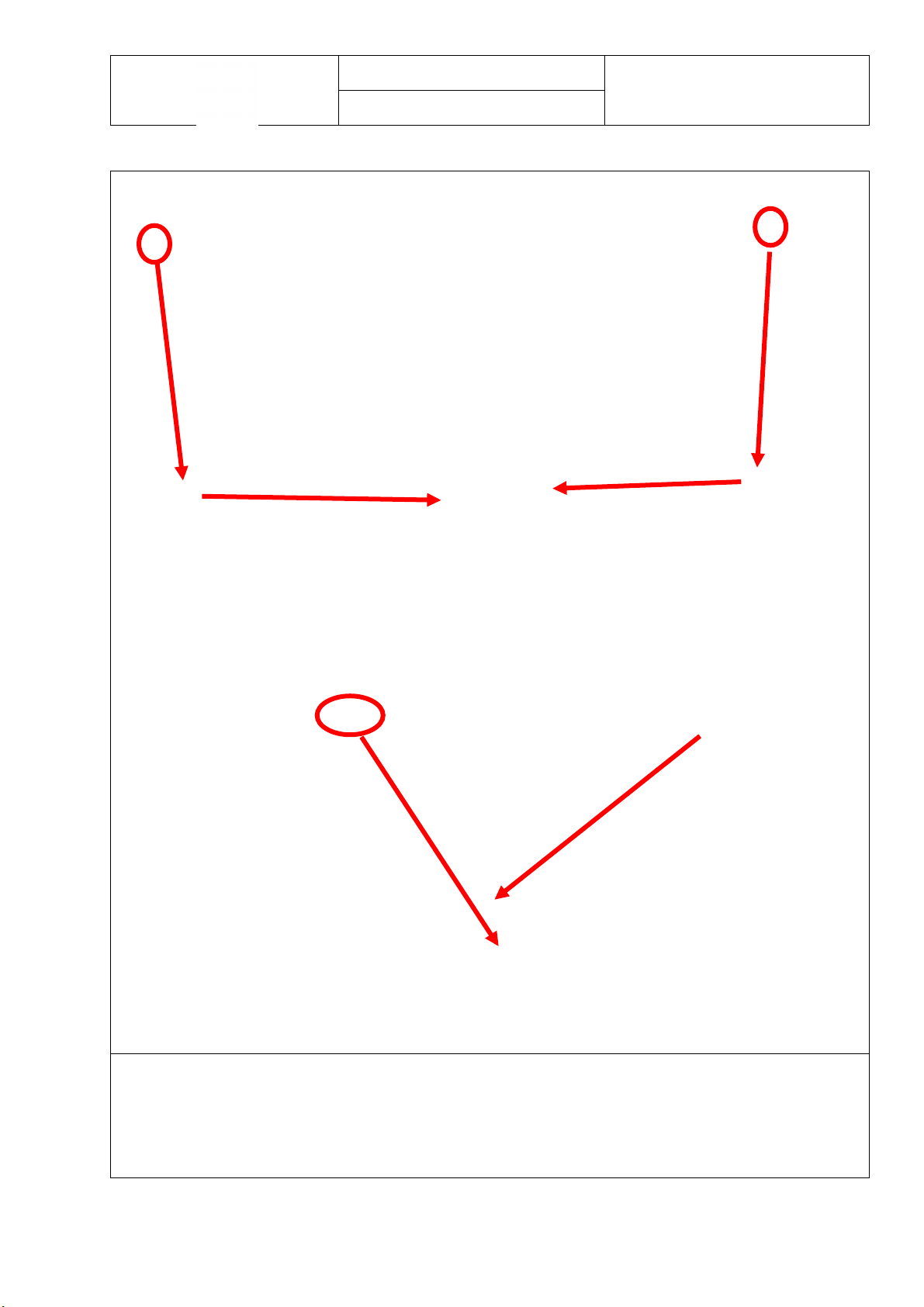
6.2. Control Panel
1. Remove 2 screws from the top
2. After the water tank removed, the plastic screw in the center of the control panel should
be removed.

HP T2 PANEL
SERVICE MANUAL
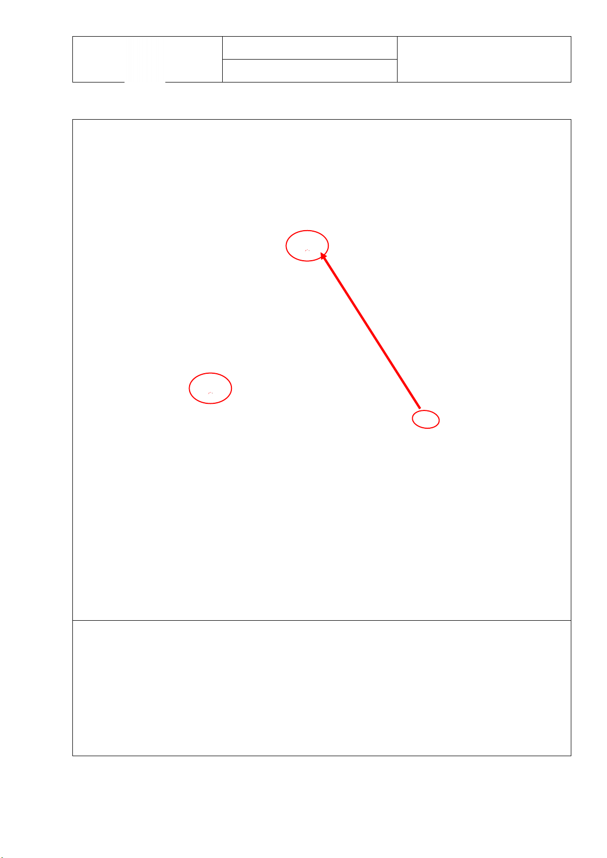
6.2. Control Panel
1. After removing the screws on the control panel, the control panel is removed as shown in the
photo from the upper support bracket.
2. The cables on the control panel are carefully removed from the cable paths.
3. All sockets which is connected with electronic card must be removed carefully as shown in the
photo.
HP T2 PANEL
SERVICE MANUAL
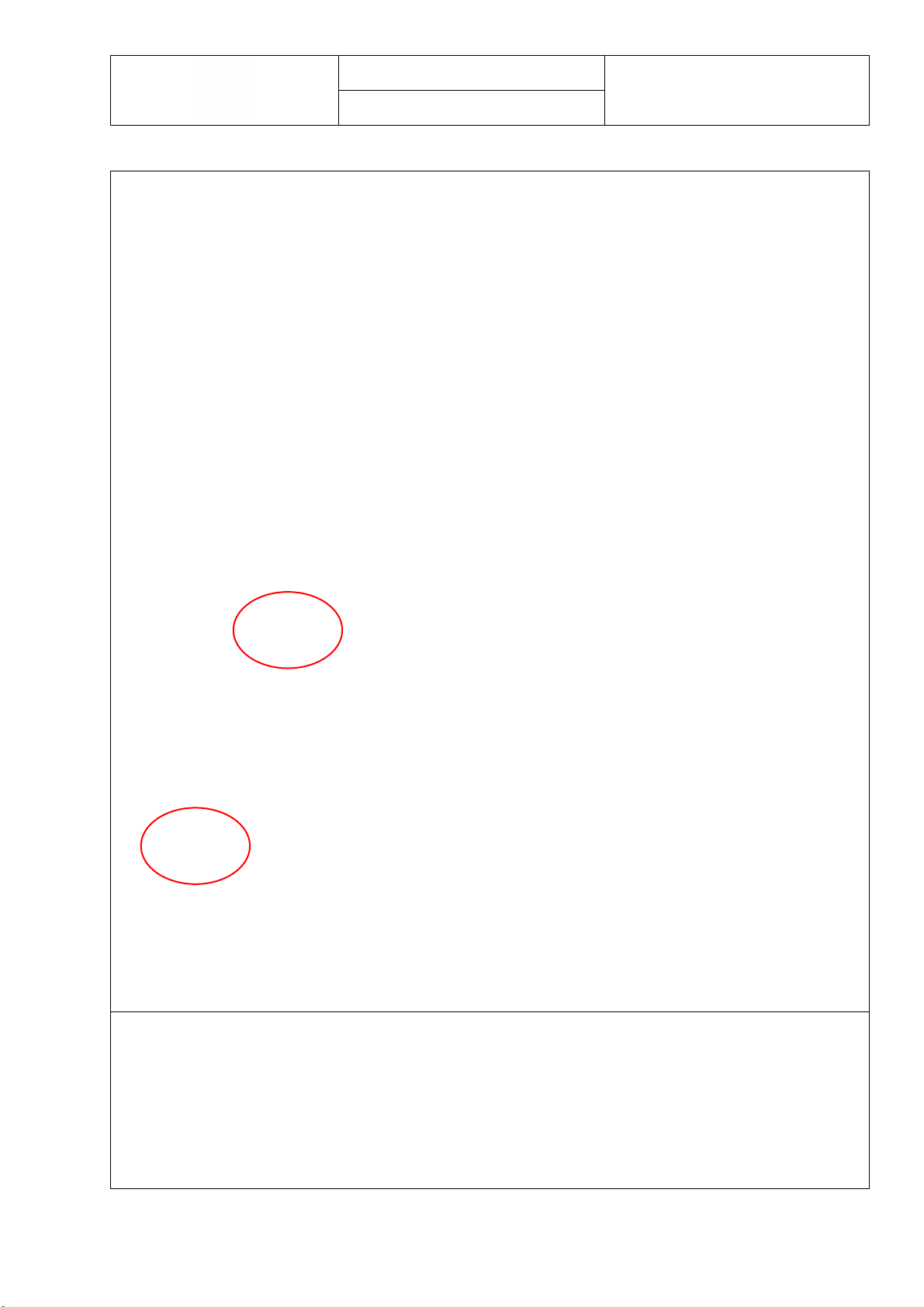
6.2. Control Panel
4. Remove the PCB box by pressing clips which provide fixing to panel So, PCB box will be separated
from control panel

HP T2 PANEL
SERVICE MANUAL
6.3. Inverter Card Box
1. All sockets which is connected with inverter card box must be removed carefully as shown in the
photo.
2. After removing the sockets on the card box, the inverter card box is removed as shown in the
photo from the side panel.
HP T2 PANEL
SERVICE MANUAL
6.3. Inverter Card Box
1. For opening the Inverter card box, press the clips (6 units) Care should be taken not to break the
clips here.
2. The inverter card inside is removed from the nails as shown in the photo.

HP T2 PANEL
SERVICE MANUAL
6.4. Electronic Card
3. For opening the PCB box, press the clips (6 units) Care should be taken not to break the clips
here.
4. The electronic card inside is removed from the nails. Remove the electronic card from pcb box
as shown in the photo

HP T2 PANEL
SERVICE MANUAL
6.5. UI Card
1. Remove screw on UI card as shown in photo.
2. Display card on control panel is disassembled as shown in photo.

HP T2 PANEL
SERVICE MANUAL
6.6. Side Panel
1. Remove 10 screws on side panels
Other manuals for HP T2
1
Table of contents
Other SOGEDIS Dryer manuals


Popular Dryer manuals by other brands

Frigidaire
Frigidaire GLEQ221A Factory parts catalog

JLA
JLA D3030 installation manual

Grundig
Grundig GT77823WHF12 user manual

Bosch
Bosch WTN85420ME Installation and operating instructions

Beko
Beko DRYPOINT M PLUS DM 40-61 C-N Instructions for installation and operation

Miele
Miele T 4819 Ci operating instructions


