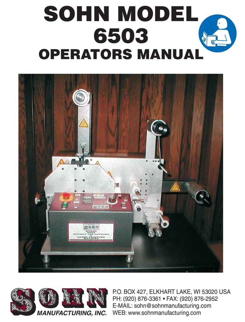
Sohn 4400 User manual

SOHN MODEL
4400
OPERATORS MANUAL
P.O. BOX 427, ELKHART LAKE, WI 53020 USA
PH: (920) 876-3361 • FAX: (920) 876-2952
E-MAIL: sohn@
WEB: www.sohnmanufacturing.com
sohnmanufacturing.com
MANUFACTURING, INC.

THIS MACHINE IS FOR INDUSTRIAL USE ONLY
IN AN INDUSTRIAL ENVIRONMENT
Sohn has supplied guarding to its best ability on all electrical components,
shafts, power drives, pulleys, belts and on objects that are designed to be
objects in motion or considered by Sohn to be obvious operator danger
points. However, due to the variances in OSHA Codes, which allows OSHA
Inspectors to determine OSHA violations in accordance to their
interpretation of OSHA Codes.
Sohn does not warrant the machine to meet all OSHA requirements, which
can vary in accordance to the location and OSHA Inspectors. It is agreed
that in accepting this proposal, the meeting of final OSHA requirements for
operation in their facility is the responsibility of the customer.
1

ATTENTION
These warning symbols are used throughout this manual
and on the machine.
Know and understand their meaning.
A
ENTANGLEMENT HAZARD (CHAIN DRIVE)
B
ELECTRIC SHOCK HAZARD
GENERAL WARNING
C
HAND ABRASION
F
PINCH POINT (HAND IN ROLLERS)
E
ENTANGLEMENT HAZARD (HAND IN GEARS)
D
HAND ENTANGLEMENT
G
CUT / SEVER HAZARD
J
NO ACCESS FOR UNAUTHORIZED PERSONNEL
H
HAIR ENTANGLEMENT
I
DO NOT REMOVE GUARD
K
WEAR EYE PROTECTION
L
READ MANUAL
M
READ SERVICE MANUAL
N
ARM ENTANGLEMENT
2
O
NOT A LIFT POINT

GENERAL SAFETY RULES
WARNING
READ THE FOLLOWING INSTRUCTIONS BEFORE OPERATING THIS MACHINE
This machine was designed for certain applications only. Sohn Manufacturing strongly
recommends that this machine not be modified and/or used for any application other than that for
which it was designed. If you have any questions relative to a particular application, DO NOT use
the machine until you have first contacted Sohn Manufacturing to determine if it can or should be
performed on the machine. As with all machinery, there are certain hazards involved with the
operation of the product. Using the machine with respect and caution will considerably lessen the
possibility of personal injury. However, if normal safety precautions are overlooked or ignored,
personal injury to the operator may result. Safety equipment such as guards, goggles and hearing
protection can reduce your potential for injury. But even the best guard won’t make up for poor
judgment, carelessness or inattentiveness. and exercise in the
workplace. :Your personal safety is your responsibility.
1. DO NOT OPERATE THIS MACHINE UNTIL it is assembled and installed according to the
instructions. FOR YOUR OWN SAFETY, READ INSTRUCTION MANUAL BEFORE
OPERATING THE MACHINE. Follow all wiring codes and recommended electrical
connections.Learn the machine’s application and limitations as well as the specific hazards
peculiar to it. OBTAIN ADVICE from your supervisor, instructor, or another qualified person
if you are not familiar with the operation of this machine.
2. DO NOT OPERATE MACHINEWITHOUT GUARDS IN PLACE.
3. KEEP WORK AREA CLEAN. Cluttered areas and benches invite accidents. NEVER
START THE MACHINE before clearing the web of all objects (tools, scrap pieces, etc.)
4. DON’T USE IN DANGEROUS ENVIRONMENT. Don’t use this machine in damp or wet
locations, or expose them to rain.Keep work area well lighted.
5. KEEP CHILDREN AND VISITORS AWAY. Children and visitors should be kept a safe
distance from work area.
6. WEAR PROPER APPAREL. No loose clothing, gloves, neckties, rings, bracelets, or other
jewelry to get caught in moving parts. Nonslip footwear is recommended. Wear protective
hair covering to contain long hair.
7. KEEP ARMS, HANDS, FINGERS away from all moving parts of the machine. DON’T
OVERREACH.Keep proper footing and balance at all times.
8. USE RECOMMENDED ACCESSORIES. The use of accessories and attachments not
recommended by Sohn Manufacturing may cause hazards or risk of injury to persons.
Always use common sense caution
REMEMBER
WARNING: FAILURE TO FOLLOW THESE RULES MAY RESULT IN SERIOUS PERSONAL INJURY
3

9. NEVER STAND ON MACHINE. Serious injury could occur if the machine is tipped or if the
rotary die is accidentally contacted.
10. CHECK DAMAGED PARTS. Before further use of the machine, a guard or other part that is
damaged should be carefully checked to ensure that it will operate properly and perform its
intended function – check for alignment of moving parts, binding or moving parts, breakage
of parts, mounting, and any other conditions that may affect its operation. A guard or other
part that is damaged should be properly repaired or replaced.
11.TURN THE MACHINE “OFF” AND DISCONNECT THE MACHINE from the power source
before installing or removing accessories, before adjusting or changing set-ups, or when
making repairs.
12.NEVER LEAVE MACHINE RUNNING UNATTENDED. TURN POWER OFF. Don’t leave
machine until it comes to a complete stop.
13.CERTAIN MATERIALS will generate unusually high noise levels. When using such
materials, test to determine the necessity of hearing protection.
14.CERTAIN DIES, i.e.dies with very deep engravings, could become a severing hazard.
15.STAY ALERT. WATCH WHAT YOU ARE DOING, AND USE COMMON SENSE WHEN
OPERATING THIS MACHINE. DO NOT USE MACHINE WHILE TIRED OR UNDER
MEDICATION. A moment of inattentiveness while operating machinery may result in
serious personal injury.
16.THE RECORDED DECIBEL LEVEL OF THIS MACHINE IS 81.9 DECIBELS AT MAXIMUM
RUNNING SPEED.
Sohn's versatile 4400 Series Label Printer is the first label printing machine designed for in-plant use that is simple to operate and
produces high quality printed die-cut labels with capabilities of 1-4 colors.
Our Model 4400 Label Printer brings the capabilities of a commercial printer inside your own facility. Our unit will eliminate costly
inventory, long lead times, expensive set up charges and high quantity minimum order requirements. The Model 4400 will produce
premium single or multi-colored labels when you need them. Printing the exact number of labels you need saves time and reduces
waste. Labels can be printed on pressure-sensitive, gummed or ungummed stock. They can be made from high gloss, litho, colored,
fluorescent, tag, foil, acetate material and many other materials. Designed for high speed operation, the unit prints, die-cuts any
shape and rewinds the waste matrix and finished labels in one roll to roll operation. This machine has sheeting capabilities and a
pressurized shut off on the heating system.
The Model 4400 has 4 flexographic print stations, each with lateral and longitudinal registration control. Print stations are designed
to use state of the art photopolymer printing plates. An optional “quick change” plate mounting system is available which will reduce
set up times on repeat runs. Die cutting configuration options includes 3 die cutting stations or laminating capabilities with running
longitudinal registration control.
Sohn's 4400 Series label makers are engineered for a long service life of continuous usage with minimum maintenance. Standard
electrical components include a proven, fuse protected, solid state variable speed DC motor drive and automatic shut off counter.
SAVE THESE INSTRUCTIONS
Refer to them often and use them to instruct others.
CALL SOHN MFG., INC. AT 920-876-3361
WITH QUESTIONS AFTER READING
THE GENERAL SAFETY RULES AND
THE OPERATING INSTRUCTIONS.
4

CONTROL PANEL SWITCHES & OPERATION
CAUTION
THIS MACHINE SHOULD BE OPERATED ONLY BY PERSONS TRAINED
IN IT'S FUNCTIONS, HAZARDS AND POTENTIAL DANGERS!
Twist
Power Switch #1 (Green)
Emergency Stop #2 (Red)
Dryer Switch #3
Counter #4
Setting
Run Speed Knob #5
Start #6
Stop #7
STOPs
Run / Jog #8
I/O - On / Off Lighted Rocker Switch controls machine power.
This red button deactivates the machine. the knob to reset.
This switch activates the dryer. Once the machine starts running, the dryer will start. When the
machine is stopped, the dryer will stop.
Function - This Counter functions to stop machine operation when the prescribed roll length
(footage) has been processed. It's preset number would normally be set to the length of a full
roll of material.
Red Button -Count Reset
P Button -Used only during initial programming of the counter.
Left Arrow -This button selects one of the digits for presetting.
Each press of the button will advance to the next digit.
Up Arrow -Pressing this button will advance the preset count for the selected digit.
This dial sets the processing speed for the machine.
Pressing this switch initiates machine motion.
Pressing this switch machine motion.
This switch selects between continuous running or intermittent operation at jog speed, when
the Start button is pressed.
min
x
123
4a
1
234567
8
AUX. 1

D
DE
G
DEG
WEB DIRECTION
WEB DIRECTION
5

F
N
D
D
E
E
F N
ED
6
O

THREADING THE MACHINE
TRACKING THE PAPER
An important step in the operation on the 4400 is the initial setup of the roll stock on the unwind shaft. If done
properly, the paper will track through the machine and onto the rewind without any problem. The following steps
will assist you in setting up the unwind, rewind and the waste to insure proper feed throughout the operation.
In order to achieve proper feed and tension, it is first important that the roll stock be wound tight and free from
any buckles. To check this, lay the roll on a flat surface, grasp the web until the slack is gone from the roll. This is
called "jogging" the roll.
Place the roll stock onto the unwind shaft with the tail unwinding counter clockwise. (see Fig. 1). Measure the
roll web width and mark the center of the roll. Measure 4" from the machine sideplate to the center mark on the
roll stock. This gives you your reference point. (See Fig. 2)
Insert the core lock pin and turn it on edge in order to secure the core to the unwind shaft. Pull out enough
stock to reach over the top of the web guide bar. At this point, it will be helpful to make a center mark on the stock
just before the guide bar. Measure 4" from the sideplate to this mark and set the paper guide accordingly. The
guides should be touching the edge of the stock as not to buckle it or leave too much space for travel side to side.
Disengage the nip roller assembly. This is done by pushing upward on the nip tie bar until the lock pin engages.
(see Fig. 4). This will keep the nip roller away from the anvil shaft. Thread the label stock between the anvil shaft
and the nip on the first station. Continue pulling stock upward past the anvil shaft on each print station. Pull the
stock over the top of the die anvil shafts and down toward the rewind spindle.
Place a core which measures the same width as your paper web on the rewind shaft. Tape the leading edge of
your stock to the core, making sure to center it. Insert the core lock pin. Measure out 4" from the sideplate to
paper center and turn the core pin until it is holding securely. You are now threaded and ready to run the machine
to check for proper tracking.
Proper tracking is crucial when printing roll to roll. A variety of factors can affect how paper tracks. The
following guidelines will help you achieve proper tracking with minimal waste.
With the nip roller disengaged, turn the machine on and run it very slowly. Your paper should track through the
machine being pulled by the tension on the rewind.
Engage the nip roller (see Fig. 3). The nip is now driving your paper through the machine. There should be
enough tension on the rewind spindle to keep up with the roller. Observe how your stock is traveling through the
machine. If it is not winding up straight, you may have to move the rewind core slightly one way or the other. Once
you have the paper tracking straight, turn the machine off.
Once you have the paper tracking properly, you are now ready to set up the print stations and rotary dies.
Fig. 2 Fig. 3
Fig. 1
PACER NIP
ENGAGED WITH ANVIL
Fig. 4
NIP TIE BAR
LOCK PIN
7

PART NO. DESCRIPTION QTY. PRICE / EA.
1
2
3
4
5
6
7
8
9
10
11
12
13
Die Anvil Shaft (1/8 Pitch)...........................................
Die Anvil Gear (1/8 Pitch)...........................................
Bearing (Anvil)...........................................................
Bearer Shaft................................................................
Bearing (Die Bearer).................................................
Die Bearer Assembly Complete..................................
Flange Nut...................................................................
Pressure Knob............................................................
Pressure Bar...............................................................
Adjusting Screw...........................................................
Set Screw....................................................................
Bearing Block Assembly.............................................
Oil Wiper Assembly (Operator Side).............................
Oil Wiper Assembly (Gear Side)...................................
1
1
2
1
2
1
4
2
2
2
2
2
1
1
DIE STATION ASSEMBLY
8
1
23
4
5
6
8
9
10
11
13 12
7

PART NO. DESCRIPTION QTY. PRICE / EA.
1
2
3
4
5
6
Die Bearer Assembly Complete...............................
Flange Nut..............................................................
Pressure Bar...........................................................
Right Bearing Block Assembly.................................
Left Bearing Block Assembly...................................
Advance or Retard Knob..........................................
DIE STATION ASSEMBLY
9
3
2
1
45
6
SETTING UP THE ROTARY DIE CUTTING
1. The rotary cutting die should be placed in the die station. This is done by putting the bearing blocks on the
die shaft. The numbers located on the blocks will tell you which way they are to be positioned. For example, if
your die tooth number falls between 32-53 it should be positioned so you can read the numbers 32-53 as shown
in figure 3. If your number falls between 54-74 it should be positioned so you can read the numbers 54-74 as
shown in figure 4.
When the die is in position, place the pressure bar over the bearing blocks. Tighten down the nuts. Follow
this procedure for both sides. Simultaneously turn down the pressure dial until the threaded stud hits the
bearing block. Applying the uniform pressure is very important in order to insure a proper die cut.
2. Run the machine and allow it to make several die cuts into the printed impression. Check to make sure
you are cutting properly by peeling a die cut label from the liner. If the label does not come off the liner cleanly,
additional pressure may be necessary. Run the machine forward until a printed impression is on the die anvil.
Position the die cavity over the image as close as possible by eye. This is done by loosening the pressure dial
enough to allow you to lift the die free from the anvil gear. You can then turn the die until you are in registration.
3. Reset the die. Run the machine forward and check the registration of your die cut according to the printed
image. Fine adjustment can now be done by using the advance or retard knobs. (See Illustration) Once the die
cut and printed image are in sync, you are ready to strip the waste and print labels. In order to strip the waste,
peel a label from the web behind the die station. Take up the two waste edges and stick them to the core on the
waste rewind shaft. This will remove the "waste matrix" as we print. Only enough tension should be put on the
waste rewind in order to keep up with the stock. Too much tension will cause the matrix to break.

PRINTING
To set up for printing, we will have to decide how many stations we need. The number of colors in our
label will determine this. Each station is set up exactly the same. The following set of guidelines will enable
you to set up and print in a very short period of time.
1. First place the print adjustment bearing block onto the print cylinder shaft, opposite the gear. Place
the drive side bearing block on the gear side of the print cylinder. Before sliding on the print cylinder, put one
spring plunger on each rod. Holding the print cylinder with both hands, slide the bearing blocks onto the
print guide rod until the print cylinder gear and the anvil gear mesh. (See illustration on following page).
2. Next, slide the impression adjustment blocks onto the print station guide rods and tighten the set
screws. Place two spring plungers on each guide rod, slide the ink fountain onto the print station guide rods.
Push the fountain toward the print cylinder holding the fountain firmly. Slide a fountain adjustment collar
onto a guide rod. Lock down the adjustment collar by turning the set screw on the side of the collar. Repeat
this on the opposite side.
3. At this point, the gear on the print cylinder and the gear on the ink fountain may not mesh. The two
nylon adjustment screws are located on the adjustment collars. Turn these clockwise until both gears mesh.
With the machine running, slowly turn the nylon adjustment screws in until ink begins to transfer from the ink
roller to the printing plate. NOTE: It is important that the fountain be brought in squarely. Advance the
screws until the print appears on the paper. You may now adjust the screw until clean, crisp print appears
throughout the impression. Repeat this procedure for each print station.
After completion of print set-up;
Blowers for drying of the ink may be placed between stations, four may be used. Four blower heads are
located in a storage rack on the back of the machine. Remove blower head from storage rack and place
between print stations. Align the pins on the head with the holes in the blower mount blocks. With blower
head in place, run machine before turning on blower switch (aux.1).Only use as many blower heads as your
application requires.Use of all blowers when not necessary may affect the performance of the ink.
NOTE: The above instructions are designed to explain print set up only. The following instructions will
dwell on proper registration, set up and running registration, along with the fine adjustments that may be
needed to achieve quality print.
FOLLOW THESE INSTRUCTIONS AND ILLUSTRATIONS CAREFULLY. THIS WILL ALLOW FOR
QUICK SET UPWITH MINIMAL WASTE.
Now that we have established how to get print onto our stock, it will be necessary to register the print both
along and across the web. This particular phase of printing will require some patience and practice.
However, by following the list of instructions and illustrations, you will be printing quality labels in only a short
time.
All print registration will be done in conjunction with the first print station (bottom). This particular station
remains as a constant for all registration. Run the machine slowly and engage the ink fountain. Move the
ink fountain inward using the adjustment collars until uniform covering is observed across the printing plate.
NOTE: Excessive ink fountain pressure against the plate may cause damage to the printing plate. In
order to achieve uniform impression, adjustment to the print cylinder adjustment blocks may be necessary.
NOTE: If at this point you are printing only one color, you should now set the cutting die. The next steps
will explain how to set the rotary cutting die.
CAUTION: Keep hands and loose fitting clothing away from all moving parts on this machine. Always
turn the machine off when making adjustments.
PRINT REGISTRATION & IMPRESSION ADJUSTMENT
10

MODEL 4400
PRINT STATION
11

PRINT REGISTRATION & IMPRESSION ADJUSTMENT
(Multi Color)
The following set of instructions are to assist you in setting up the press for a multi color label.
The same guidelines will remain for the first station as in printing with one color. The second print
station should be set up at this time.
1. Run the machine forward and mark, with a pen, the beginning cavity by the first set of tick
marks. Run this marked label forward to the second station anvil shaft. Position the forward cavity
registration marks (tick marks) on the second printing plate, in line with the tick marks left on the
web by the first printing plate. (See Illustration)
Push in the print cylinder on the corresponding tooth until the gears mesh. Push in the ink
fountain and tighten the fountain adjustment collar set screw.
2. Run the machine slowly and
again move the ink fountain inward
to achieve print. Once this is done,
observe where the second
impression is registering in
comparison with station number
one. If you are close to proper
registration, you can advance or
retard the impression by using the
registration knob for that station.
(see below). If registration cannot
be achieved by use of the advance
or retard, you will have to move the
print cylinder to the proper tooth
manually.
NOTE: Before attempting any
adjustment, the machine should be
shut off.
After moving the print plate, check
the impression again. You now
should be able to register using the
registration knobs. Once this is
done you can now set your die cut
and remove waste. Repeat the
above procedure from each plate.
REGISTRATION KNOB
12

INK FOUNTAIN CLEANING INSTRUCTIONS
MODEL 4400 MACHINE
DISASSEMBLY:
WASHING FOUNTAIN
REASSEMBLY:
It is recommended to disassemble and clean the fountain at the end of the days of production.
1. Remove ink fountain from the machine and place on flat surfaces. Loosen doctor blade screws.
2. Use 5/32 Hex Wrench to remove cover screws. Remove cover.
3. Lift out ink roller. Remove gear, bushings and seals.
4. Inspect doctor blade assembly and "O" rings for need of replacement.
1. Wash in Type B Cleaner.
2. Wash in Type C Cleaner.
3. Rinse in water. Dry with paper towel.
1. Put seals, bushings and gears onto ink roller shaft. (Be certain that the gear side and non-gear side seal
are on the correct ends.
2. Place this assembly into the ink fountain. The flat surface of the bushings must be in the up position. The
pins on the seals must be in the bottom corner of the fountain. (This will position the notches in the seals in
the up and slightly back position. The doctor blade will sit in these notches when the cover is replaced).
3. Put the cover on. Use 5/32 HexWrench to tighten cover screws.
4. Put small amount of pressure on doctor blade screws.
The ink fountain is the heart of your printing machine. Use a regular cleaning schedule and keep the
fountain away from lint and dust. Extreme gear wear and bad printing can often be traced to a dirty fountain.
Inspect the doctor blade regularly and replace if excessive wear is apparent.
It is recommended that the ink fountain be returned to the factory for inspection and maintenance if
excessive wear or malfunction is apparent.
13
DIMPLES
FLATS
SET SCREWS
ATTENTION
FAILURE TO DO SO WILL CAUSE
DAMAGE TO THE SHAFT.
When re-assembling the ink fountain gear
to the fountain roller shaft the set screws
in the gear must be aligned with the
dimples in the shaft.
NOTE: RIGHT & LEFT SEALS ARE DIFFERENT.
The right side is stamped G for gear side.
When placing the seals back on the ink roller, the
flat should face the back of the fountain at a
45° angle as shown in the above photo.
It is very important to have the flats in the
correct position for the doctor
blades to work properly.

Before inking up the system, it is first necessary to understand the ink fountain itself. It will be essential to know how to
dismantle and clean your ink fountains. This is probably one of the most important steps in getting good, quality print.
The ink fountains on the Model 4400 are designed to hold approximately two ounces of flexographic ink. They are
equipped with a reverse doctor blade assembly which is designed to enhance print quality and extend the life of the ink roller.
One very important part of the ink system is the maintenance and cleaning of the fountains. A fountain which is not
cleaned properly will not perform the way it was designed to. In order to clean the ink fountain, it must be partially
disassembled. This can be done quickly and easily by following the cleaning and assembly instructions.
PART NO. DESCRIPTION QTY. PRICE / EA.
1
2
3
4
5
6
7
8
9
10
11
12
13
14
15
Dipstick......................................................................
Reverse Dr. Blade Assembly........................................
Reverse Dr. Blade.......................................................
Screw, Brass Knurled..................................................
Reverse Dr. Blade Pressure Block..............................
Reverse Dr. Blade Mount............................................
Fountain Carrier Bracket......................................
Screws, Fountain Carrier Bracket Assembly...............
Fountain Body, Coated................................................
Fountain Bushing........................................................
Ink Roller...................................................................
Ink Roller Gear.......................................................
Fountain Seal (left)....................................................
Fountain Seal (right)...................................................
O-Ring........................................................................
1
1
1
2
1
1
1
4
1
2
1
1
1
1
2
INK FOUNTAIN ASSEMBLY
14
1
2
34
5
6
7
88
9
10
11
12
13
14 15
15
4400 INK FOUNTAIN ASSEMBLY AND CLEANING

1. Labels not die-cutting completely. A. The cutting die may have a low spot or nick in it.
B. Paper liner too thin.
A. Return to factory to have die checked and reground.
B. Use only Sohn Paper Stocks.
2. Unit does not start. A. No number on automatic counter. A. Reset shut-off counter.
3. Label is too short. A. Infeed tension incorrect.
B. Adhesive buildup in guides.
C. Pacer Roller not adjusted properly
A. Re-adjust pacer roller in or out.
B. Remove guide top plate and clean all parts.
C. Re-adjust pacer roller in or out.
4. Label is too long. A. Infeed tension incorrect.
B. Rewind assembly pulling web too strongly.
A. Re-adjust tension nut on the unwind spindle.
B. Adjust or clean rewind assembly. Rewind only required
to take up paper slack as it is printed.
6. Blank spots on printed label. A. Stickyback worn out.
B. Low spots in printing plate.
A. Replace stickyback.
B. Replace stickyback or shim individual low spots by
applying small pieces of transparent tape on cylinder
surface under the low spots.
7. Printed matter is squashed. A. Too much pressure on print cylinder shaft.
B. Bubbles under stickyback when applied to print
cylinder.
A. Re-adjust die adjust screws using instructions on
Page 1.
B. Poke bubbles with sharp tool. Roll bubbles out from
under stickyback.
8. Ink does not dry properly. A. Too much ink flow between ink roller and doctor blade.
B. Wrong type of ink.
C. Ink has lost its viscosity.
A. Turn down slightly on doctor blade adjustments until
correct amount of ink is obtained.
B. See Page 5.
C. If ink is too thick, add thinner. Do not overfill fountain. If
ink is too washed out, add more ink.
D. Use Sohn recommended paper.
10. Paper sticks to printing plate and wraps around shaft. A. Ink has built up on printing plate and dried from
standing.
B. ink has lost its viscosity.
A. Maintain proper doctor blade adjustment. Clean excess
ink from printing plate before starting up.
B. Add thinner to ink.
11. Label appears shaded or streaky immediately upon
printing.
A. Ink roller is too smooth
B. Doctor blade worn out.
A. Submit ink roller for reconditioning.
B. Replace doctor blade.
5. Label length varies. A. Combination of 3 & 4. A. See 3 & 4.
9. Printing is slurred or smeared. A. Too much infeed tension.
B. Pacer roller not driving paper through machine.
C. Too much ink on printing plate.
D. Ink has lost its viscosity.
A. Relieve tension until good printing is obtained.
B. Re-adjust pacer roller in or out.
C. Back out ink fountain, clean plate and re-ink.
D. If ink is too thick, add thinner. If ink has too much
thinner, add ink. Do not overfill fountain.
TROUBLE-SHOOTING GUIDE
PROBLEM CAUSE CURE
15
PREVENTIVE MAINTENANCE
Use regular motor oil (10w-30) on the following areas weekly:
1.Top hole in each bearing block on die.
2.Two holes on each side of anvil shaft.
3.Light film of oil on the bearers of the die.
Use regular automotive grease on the following areas monthly, clean and re-lube.
1. Die gears.
2. Anvil shaft gears.

SOHN MODEL
4400
MANUFACTURING, INC.
P.O. BOX 427, ELKHART LAKE, WI 53020 USA
PH: (920) 876-3361 • FAX: (920) 876-2952
E-MAIL: sohn@
WEB: www.sohnmanufacturing.com
sohnmanufacturing.com
Other manuals for 4400
1
Table of contents
Other Sohn Power Tools manuals
Popular Power Tools manuals by other brands

Baileigh
Baileigh SH-120250-HD Operator's manual

Wurth Master
Wurth Master SBS 1300-VES Translation of the original instructions

Klein Tools
Klein Tools BAT20-12T165 SERIES instruction manual

Avvio
Avvio C192069 Operator's manual
HIKOKI
HIKOKI SB3608DA Handling instructions

Milwaukee
Milwaukee HD28 JSB Original instructions
