Sohn 6503 User manual
SOHN MODEL
6503
OPERATORS MANUAL
MANUFACTURING, INC.
P.O. BOX 427, ELKHART LAKE, WI 53020 USA
PH: (920) 876-3361 • FAX: (920) 876-2952
E-MAIL: sohn@
WEB: www.sohnmanufacturing.com
sohnmanufacturing.com

THIS MACHINE IS FOR INDUSTRIAL USE ONLY
IN AN INDUSTRIAL ENVIRONMENT
Sohn has supplied guarding to its best ability on all electrical components,
shafts, power drives, pulleys, belts and on objects that are designed to be
objects in motion or considered by Sohn to be obvious operator danger
points. However, due to the variances in OSHA Codes, which allows OSHA
Inspectors to determine OSHA violations in accordance to their
interpretation of OSHA Codes.
Sohn does not warrant the machine to meet all OSHA requirements, which
can vary in accordance to the location and OSHA Inspectors. It is agreed
that in accepting this proposal, the meeting of final OSHA requirements for
operation in their facility is the responsibility of the customer.
1
ATTENTION
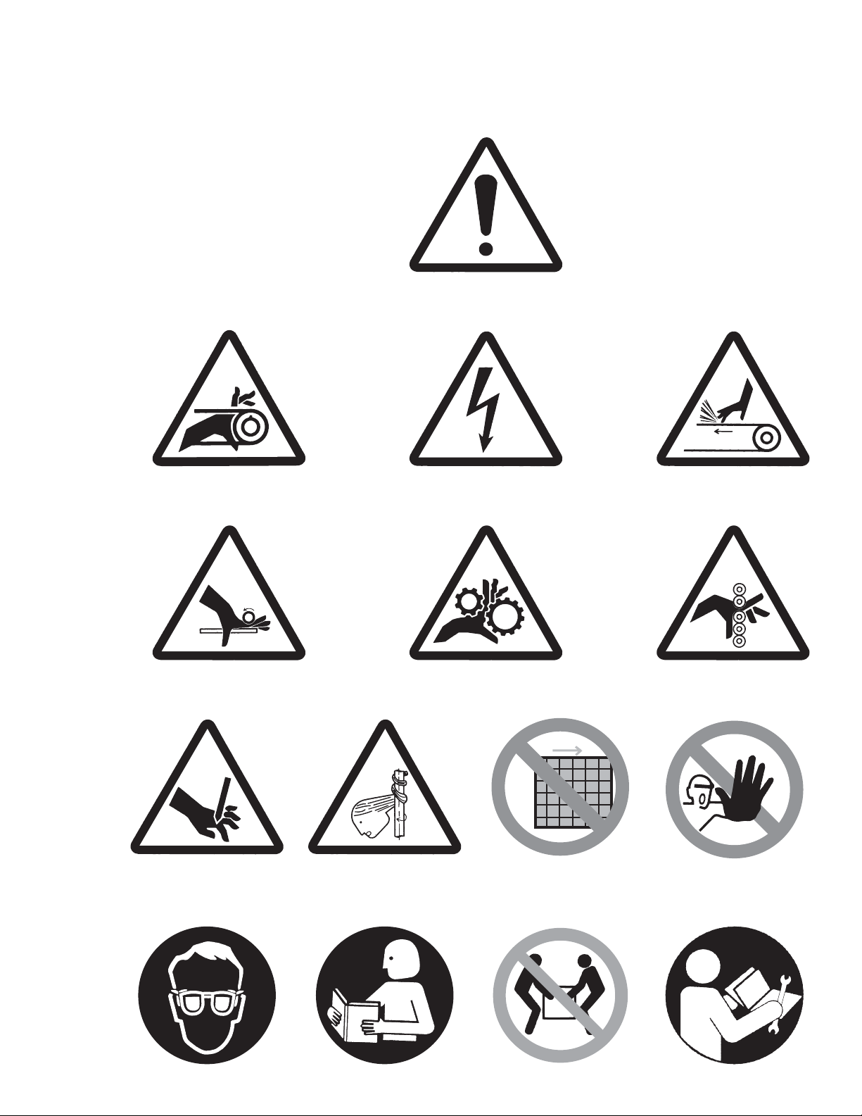
These warning symbols are used throughout this manual and on the machine.
Know and understand their meaning.
ABC
FED
ENTANGLEMENT HAZARD (BELT DRIVE) ELECTRIC SHOCK HAZARD
GENERAL WARNING
HAND ABRASION
PINCH POINT (HAND IN ROLLERS)ENTANGLEMENT HAZARD (HAND IN GEARS)
HAND ENTANGLEMENT
G
CUT / SEVER HAZARD
J
NO ACCESS FOR
UNAUTHORIZED PERSONNEL
H
HAIR ENTANGLEMENT
I
DO NOT REMOVE GUARD
K
WEAR EYE PROTECTION
L
READ MANUAL 2
M
NOT A LIFT POINT
N
SERVICE MANUAL

GENERAL SAFETY RULES
WARNING
READ THE FOLLOWING INSTRUCTIONS BEFORE OPERATING THIS MACHINE
This machine was designed for certain applications only. Sohn Manufacturing strongly
recommends that this machine not be modified and/or used for any application other than that for
which it was designed. If you have any questions relative to a particular application, DO NOT use
the machine until you have first contacted Sohn Manufacturing to determine if it can or should be
performed on the machine. As with all machinery, there are certain hazards involved with the
operation of the product. Using the machine with respect and caution will considerably lessen the
possibility of personal injury. However, if normal safety precautions are overlooked or ignored,
personal injury to the operator may result. Safety equipment such as guards, goggles and hearing
protection can reduce your potential for injury. But even the best guard won’t make up for poor
judgment, carelessness or inattention. and exercise in the
workplace. :Your personal safety is your responsibility.
1. DO NOT OPERATE THIS MACHINE UNTIL it is assembled and installed according to the
instructions. FOR YOUR OWN SAFETY, READ INSTRUCTION MANUAL BEFORE
OPERATING THE MACHINE. Follow all wiring codes and recommended electrical
connections.Learn the machine’s application and limitations as well as the specific hazards
peculiar to it. OBTAIN ADVICE from your supervisor, instructor, or another qualified person
if you are not familiar with the operation of this machine.
2. DO NOT OPERATE MACHINEWITHOUT GUARDS IN PLACE.
3. KEEP WORK AREA CLEAN. Cluttered areas and benches invite accidents. NEVER
START THE MACHINE before clearing the web of all objects (tools, scrap pieces, etc.)
4. DON’T USE IN DANGEROUS ENVIRONMENT. Don’t use this machine in damp or wet
locations, or expose them to rain.Keep work area well lighted.
5. KEEP CHILDREN AND VISITORS AWAY. Children and visitors should be kept a safe
distance from work area.
6. WEAR PROPER APPAREL. No loose clothing, gloves, neckties, rings, bracelets, or other
jewelry to get caught in moving parts. Nonslip footwear is recommended. Wear protective
hair covering to contain long hair.
7. KEEP ARMS, HANDS, FINGERS away from all moving parts of the machine. DON’T
OVERREACH.Keep proper footing and balance at all times.
8. USE RECOMMENDED ACCESSORIES. The use of accessories and attachments not
recommended by Sohn Manufacturing may cause hazards or risk of injury to persons.
Always use common sense caution
REMEMBER
WARNING: FAILURE TO FOLLOW THESE RULES MAY RESULT IN SERIOUS PERSONAL INJURY
3

9. NEVER STAND ON MACHINE. Serious injury could occur if the machine is tipped or if the
rotary die is accidentally contacted.
10. CHECK DAMAGED PARTS. Before further use of the machine, a guard or other part that is
damaged should be carefully checked to ensure that it will operate properly and perform its
intended function – check for alignment of moving parts, binding or moving parts, breakage
of parts, mounting, and any other conditions that may affect its operation. A guard or other
part that is damaged should be properly repaired or replaced.
11.TURN THE MACHINE “OFF” AND DISCONNECT THE MACHINE from the power source
before installing or removing accessories, before adjusting or changing set-ups, or when
making repairs.
12.NEVER LEAVE MACHINE RUNNING UNATTENDED. TURN POWER OFF. Don’t leave
machine until it comes to a complete stop.
13.CERTAIN MATERIALS will generate unusually high noise levels. When using such
materials, test to determine the necessity of hearing protection.
14.CERTAIN DIES, i.e. dies with very deep engravings, could become a severing hazard.
15.STAY ALERT. WATCH WHAT YOU ARE DOING, AND USE COMMON SENSE WHEN
OPERATING THIS MACHINE. DO NOT USE MACHINE WHILE TIRED OR UNDER
MEDICATION. A moment of inattention while operating machinery may result in serious
personal injury.
SAVE THESE INSTRUCTIONS
Refer to them often and use them to instruct others.
4
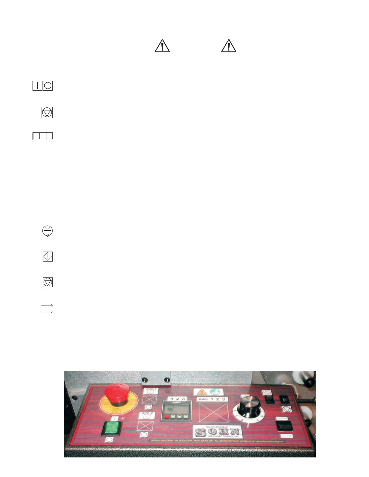
CONTROL PANEL SWITCHES & OPERATION
CAUTION
THIS MACHINE SHOULD BE OPERATED ONLY BY PERSONS TRAINED
IN IT'S FUNCTIONS, HAZARDS AND POTENTIAL DANGERS!
Twist
Power Switch #1 (Green)
Emergency Stop #2 (Red)
Counter #3
Setting
Run Speed Knob #4
Start #5
Stop #6
STOPs
Run / Jog #7
I/O - On / Off Lighted Rocker Switch controls machine power.
This red button deactivates the machine. the knob to reset.
Function - This Counter functions to stop machine operation when the prescribed roll length
(footage) has been processed. It's preset number would normally be set to the length of a full
roll of material.
Red Button -Count Reset
P Button -Used only during initial programming of the counter.
Left Arrow -This button selects one of the digits for presetting.
Each press of the button will advance to the next digit.
Up Arrow -Pressing this button will advance the preset count for the selected digit.
This dial sets the processing speed for the machine.
Pressing this switch initiates machine motion.
Pressing this switch machine motion.
This switch selects between continuous running or intermittent operation at jog speed, when
the Start button is pressed.
min
x
123
1
2
34
56
7
4a

OPERATING INSTRUCTIONS SOHN MODEL 6503
FLEXOGRAPHIC LABEL PRESS
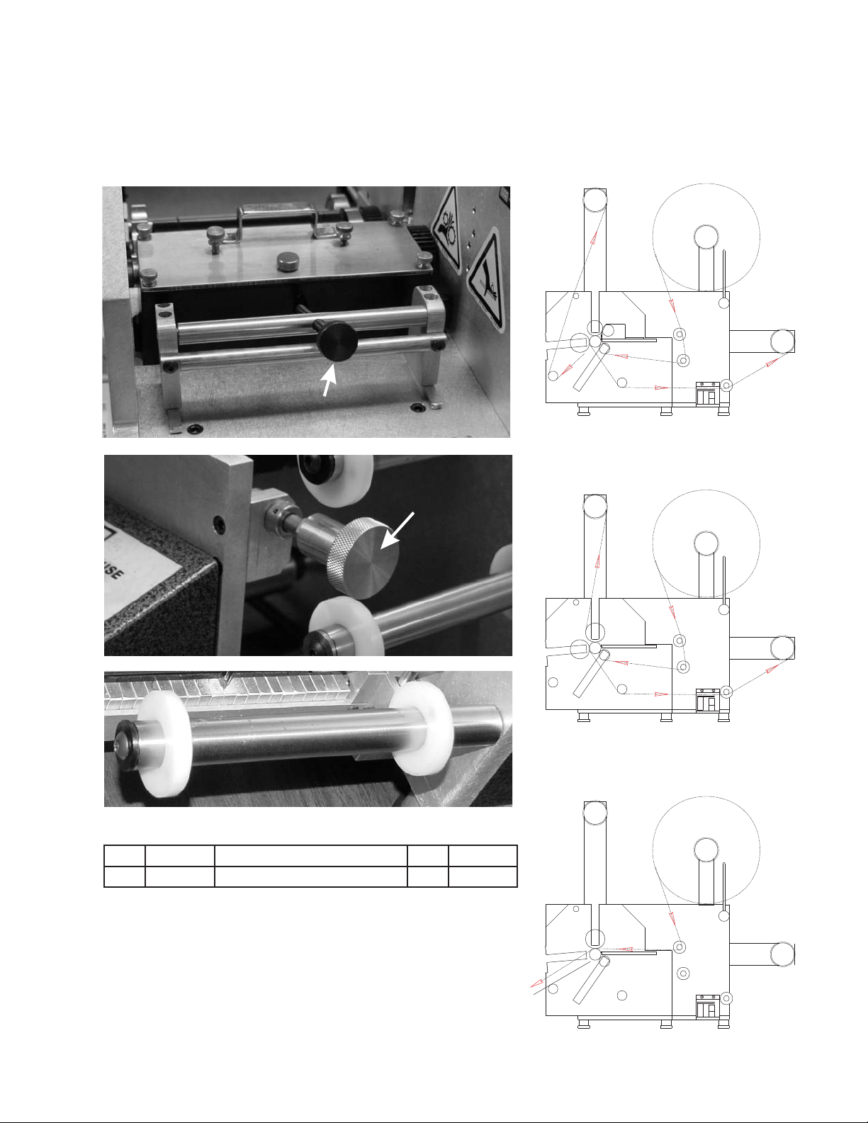
To begin set-up of the Model 6503 Flexo Printer, refer to the threading diagram. There are three
configurations that can be used. Follow these instructions for proper results.
The next step would be to center the paper to maintain proper tracking. The center of the model
6503 machine is 4" from the back plate. An example would be when using 2" wide material, a mark should
be put on the center of the roll at 1" from either edge, place the roll on the unwind spindle with the paper
unwinding to the left from the top of the roll and measure 4" to the mark on the material from the back side
plate. The material now is centered on the machine. Next thread the material thru the machine, refer to
threading diagram. The spring loaded pacer assembly must be unlocked when threading. To unlock, pull
back on the assembly until the pin locks in the back side plate. Once you have the paper threaded, place the
blank core on the unwind, attach the material to the core. At this point, the measurement of 4" is again
applied. Next the paper guides are set both on the infeed and rewind, the 4" measurement again is applied.
Slide collars to edge of paper allowing approximately 1/64" clearance on either side. This will assure proper
tracking of materials. Run machine to test for proper tracking of material. Pacer roller should be engaged at
this point.
The printing plate is affixed to the proper circumference print cylinder using .015 stickyback.
Making sure the corresponding correct gearing is used. It is then inserted into the top of the print station
making sure that the proper shaft, gear and print cylinder are utilized and the corresponding bearing blocks
in the right direction are used. You will find on the bearing blocks themselves, numbers from 61 to 91, (32
D.P.), 32 to 53 (1/8 C.P.) in one configuration and then reversing or turning the blocks upside down, you will
then be able to read from 91 to 122, (32 D.P.), 53 to 74 (1/8 C.P). This is necessary because of the large
range from 6" to 12" circumference that can be utilized on this particular press.
The bearing blocks are then put so that the T is to the inside of the machine, meaning that the
bearing blocks are T shaped and that the wider part of the bearing blocks are to be facing the center of the
unit itself. This will assure proper alignment of the gear, shaft, and print cylinder. At this point, consideration
should be given to the mounting of the printing plate on the print cylinder so that you do have some
adjustment horizontally on this shaft.
To accomplish this, there are two brass set screws in each print cylinder. Care must be taken that
this print cylinder is not torqued too tight so that the brass allen head set screw does not become rounded.
Brass is used so that scoring of the anvil shaft, scoring of the print cylinder shaft is eliminated. If steel set
screws are used, scoring of this shaft will occur which will cause difficulty in making the finer adjustments
that will be needed to center the print both horizontally and vertically with the cutting die.
The screws are added to the hold down for the bearing blocks and tightened. The two knobs now
can be tightened to bring the print cylinder and printing plate so that the printing plate just barely touches the
paper. Care must be taken to assure that the anvil shaft gear and the print cylinder shaft gear is meshed.
Next, insert the ink fountain being sure the fountain is tipped back to assure that the ink does not run out the
front of the ink fountain. Slide the fountain forward on the fountain rail assembly until it comes in contact with
the stops. Then lightly tighten the lock screw to hold the fountain in place.
In turning the unit on, a count must be on the counter in order for the unit to continue running. The
main on/off switch must be on, the toggle switch must be in run position, and the run jog button depressed to
initiate the running of the motor. The speed control can now be turned on and gradually brought to a higher
number so the unit will start revolving slowly. At this time, the ink fountain adjustment knob to the right of the
unit is to be turned slowly, advancing the ink fountain. (Care should be taken so that the ink fountain gear
and print cylinder gear mesh smoothly.) Continue advancing the ink fountain until the printing plate picks up
a slight even coating of ink completely covering the printing plate image, observing the print quality at this
time.
By depressing or relieving the adjustment screws, the ideal impression can be achieved. After the
impression has been set satisfactorily, insert the cutting die ( ) again checking the gear for the right 5
number of teeth to match that of the die and print cylinder and insert the bearing blocks and die into the die
station making sure the die blocks are put with the T to the inside of the machine. Next, place the die bearer
hold down into die station locking into place with the 4 hex nuts. Adjust die to print image.
Bring waste to waste rewind following threading diagram.
FOUNTAIN LOCKING SCREW
FOUNTAIN
ADJUSTMENT
KNOB
OPTION
ROTARY
PACER ASSEMBLY
DIE
REWIND
WASTE UNWIND
PRINT
CYLINDER
SLITTER
PRODUCT
REWIND
PRINTING/DIE CUTTING WEB PATH
PACER ASSEMBLY
ROTARY
DIE DIE
REWIND
WASTE UNWIND
ROTARY REWIND
PRODUCT
DIE CUTTING WEB PATH (2) DIES
SLITTER
OPTION
PACER ASSEMBLY
REWIND
WASTE UNWIND
ROTARY
DIE
OPTION
SLITTER
SHEETING WEB PATH
PRODUCT
REWIND
PART NO. DESCRIPTION QTY. PRICE / EA.
Paper Guide Assembly.............................. 1
PAPER GUIDE ASSEMBLY
6
E
G
GE
7
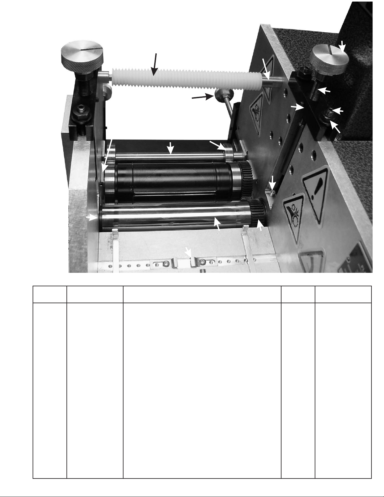
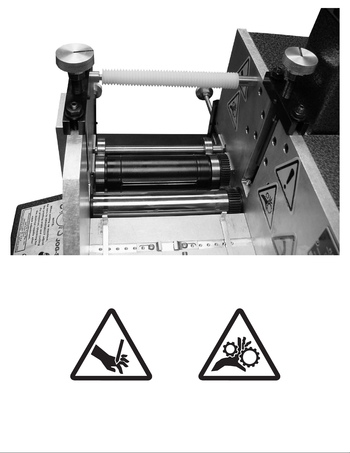
PART NO. DESCRIPTION
DIE CUTTING STATION
QTY. PRICE / EA.
1
2
3
4
5
6
7
8
9
10
11
12
13
14
15
16
1
1
1
1
2
1
4
4
1
2
8
2
2
2
4
1
1
1
1
2
12
3
4
5
678
12
13
14
16
15
9
10
11
8
Anvil Shaft 1/8 Pitch......................................................
Paper Guide.................................................................
Spring (81-122 teeth 32 Pitch / 64-96 teeth 1/8 Pitch)....
Bearer Shaft.................................................................
Die Bearer Bearing.......................................................
Die Bearer Assembly Complete....................................
Flange Nut....................................................................
Pressure Knob.............................................................
Pressure Bar................................................................
Adjusting Rod...............................................................
Set Screw.....................................................................
Right Bearing Block Assembly......................................
Left Bearing Block Assembly....................................
Waste Roller.................................................................
Tie Bar..........................................................................
Die Pressure Screw......................................................
Oil Wiper Assembly Gear Side (not shown)...................
Oil Wiper Assembly Operators Side (not shown)...........
Anvil Shaft (32 Pitch-Option).........................................
Anvil Gear 1/8 Pitch......................................................
Anvil Gear (32 Pitch-Option).........................................
Anvil Bearing................................................................
Spring (62-80 teeth 32 Pitch / 48-63 teeth .1/8 Pitch).....

PART NO. DESCRIPTION QTY. PRICE / EA.
1
2
3
4
5
Print Cylinder (various sizes)........................................
Brass Set Screw...........................................................
Print Cylinder Shaft.......................................................
Print Cylinder Gear (various sizes)................................
Screw...........................................................................
1
2
1
1
1
1
2
3
4
5
14
PRINT CYLINDER
9
PART NO. DESCRIPTION QTY. PRICE / EA.
1
2
3
4
5
6
7
8
9
10
11
12
13
14
Dipstick........................................................................
Cover Thumb Screw....................................................
Dr. Blade Thumb Screw................................................
Ink Fountain.................................................................
Fountain Line Up Tool...................................................
Dr. Blade Assembly.......................................................
Dr. Blade only................................................................
Ink Roller Gear 1/8 Pitch...............................................
Fountain Gear Set Screw..............................................
O-Ring Retainer...........................................................
Fountain O-Ring...........................................................
...........
Ink Roller Set Screw....................................................
Ink Roller Gear (32 Pitch-Option).................................
Ink Roller 1/8 Pitch.......................................................
Ink Roller (32 Pitch-Option)..........................................
Fountain Shaft 1/8 Pitch...............................................
Fountain Bushing..............................................
1
4
2
1
1
1
1
1
1
1
1
1
1
1
2
2
2
1
2
3
4
5
6
79
10 8
11
12
14
14
12
11
14
13 13
INK FOUNTAIN
10

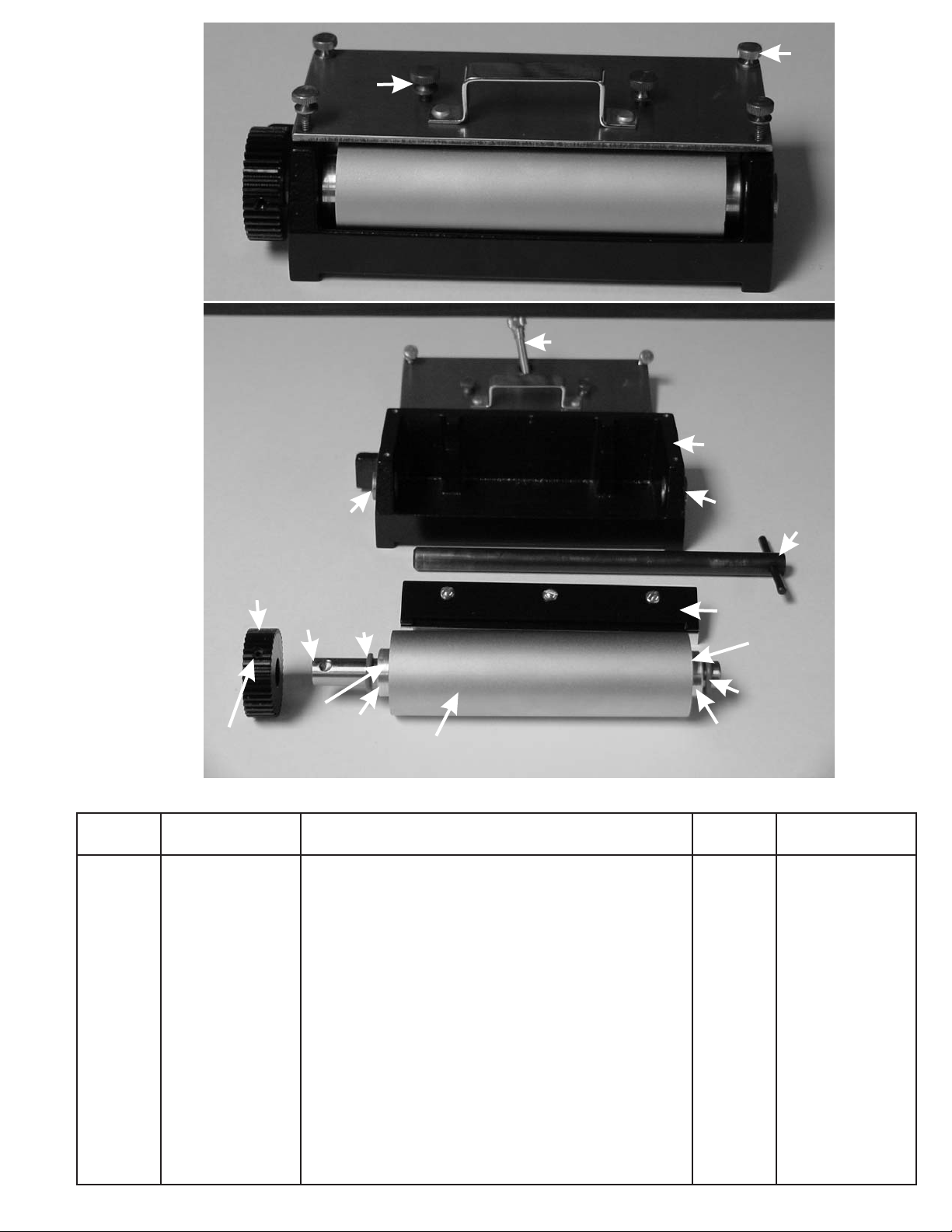
PART NO. DESCRIPTION QTY. PRICE / EA.
1 Pacer Nip Assembly...................................................... 1
1
PACER NIP ASSEMBLY
PACER NIP
ENGAGED WITH ANVIL
11

INK FOUNTAIN CLEANING INSTRUCTIONS
MODEL 6503 MACHINE
Suggest Sohn C-100 cleaning kit which contains the following essential items: Rubber Gloves, 1 Small
Handle Brush, 1 Round Brush, 1 Square Shallow Pan, 1 Scraping Knife, 1 Alignment Tool, 1 Gallon Sohn
Super Cleaner (Type C), 1 Qt.Sohn Fountain Cleaner (Type B).
It is recommended to disassemble and clean the fountain at end of job.
1. Remove ink fountain from machine and place on flat surface. Loosen Dr. Blade screws.
2. Remove the four brass thumb screws and take cover off.
3. Remove Dr. Blade assembly (inspect for need of replacement).
4. With a 3/32 allen wrench, loosen the set screws on the left and right side of the ink roller.
5. Remove the shaft and gear assembly from the ink fountain (pry with screwdriver if necessary).
1. Wash in Type C Cleaner when using water base ink.
2. Rinse in water. Dry with paper towel.
To reassemble, reverse the disassembly process. A fountain line-up tool (T-bar) should be used to
assist you in realigning the ink roller.
1. Insert the gear and shaft assembly on the left side of the fountain body (as the front of the ink
fountain is facing you).
2. Slide the "O" ring first, then the retainer onto the shaft.
3. Insert the T-bar on the right side of the fountain body.
4. Slide the "O" ring first, then the retainer onto the T-bar.
5. Place the ink roller between the retainers on the left and right side. Align the shaft of the gear and
shaft assembly into the roller on the left side, and the shaft of the T-bar into the roller on the right
side.
6. Push the gear and shaft assembly completely through, replacing the T-bar shaft.
7. Lock the set screws on the roller (there are two flat areas on the shaft. The set screws should be
tightened on these flat areas).
8. Put Dr. Blade assembly into fountain.
9. Replace cover and tighten with four brass thumb screws.
10. Put a small amount of pressure on Dr. Blade screws.
***********
The ink fountain is the heart of your printing machine. Use a regular cleaning schedule and keep the
fountain away from lint and dust. Extreme gear wear and bad printing can often be traced to a dirty fountain.
Inspect the doctor blade regularly and replace if excessive wear is apparent.
It is recommended that the ink fountain be returned to the factory for inspection and maintenance if
excessive wear or malfunction is apparent.
DISASSEMBLY:
WASHING FOUNTAIN:
REASSEMBLY:
12

ATTENTION
FAILURE TO DO SO WILL CAUSE
DAMAGE TO THE SHAFT.
When re-assembling the ink roller gear to the fountain shaft the set
screw in the gear must be aligned with the dimple in the shaft.
ATTENTION
NOTE:
FAILURE TO DO SO WILL CAUSE
DAMAGE TO THE SHAFT.
When re-assembling the ink roller to the fountain shaft the set
screws in the ink roller must be aligned with the flats in the shaft.
The flats in the shaft are in alignment with the dimple.
DIMPLE
DIMPLE
FLAT SET
SCREW
SET
SCREW
13

ORDERING INFO FOR PRINTING PLATES FOR MACHINES
USING PRINT CYLINDERS AND DIES.
In general terms, the necessary information for ordering plates for the above machines can be
stated as a description of the printed image (text, graphics and color separation information), specifications
for distortion, step and repeat corresponding to the tooling that will be used and an indication of the running
direction of the image.
The description of the image can be specified through the use of a printed sample, sketch and/or
listing of the necessary copy. In any case, it's important that the information be clear, concise and legible.
Long listings of text should be typewritten if possible. For multi-color work, information indicating color
separations should be included. Information concerning special graphic elements like bleed borders and
special color overlap should be stated explicitly.
The necessary details concerning tooling information follow:
1. MODEL OF MACHINE.
2. NUMBER OF COLORS FOR JOB.
3. WIDTH OF THE DIE CUT in the direction across the web. (This will be the width of the paper
stock in the case of butt cut labels.)
4. LENGTH OF THE DIE CUT in the direction along the length of the roll.
5. INDICATE THE SHAPE OF THE DIE CUT. This might be BUTT CUT, RECTANGULAR
(INCLUDING SQUARE), ROUND, OVAL, OR SPECIAL SHAPE. In the case of the
rectangular die cut we will also need the SIZE OF THE CORNER RADIUS, most commonly
1/8" but many dies have either a smaller or larger corner radius. In the case of an oval or
special shape it's essential to have actual samples of the labels cut by the die in question
submitted with the plate order. If the sample of the die cut has been printed it should be
marked "SAMPLE FOR DIE CUT ONLY".
6. THE NUMBER OF ROWS OF CAVITIES ACROSS THE DIE. Most often this number will be
1, but in the case of smaller die sizes this could be any number between 2 and 10 or more.
In the event that this number is greater than 1 we will also need some indication of the
SPACING BETWEEN THE CAVITIES IN THE DIRECTION ACROSS THE WIDTH OF THE
WEB. THIS CAN BE THE ACTUAL SPACE BETWEEN THE CAVITIES OR WHAT WE CALL
THE "CENTER DISTANCE ACROSS THE WEB" WHICH IS THE SUM OF THE WIDTH OF
THE CUT ACROSS THE WEB PLUS THE SPACING TO THE NEXT CAVITY ACROSS THE
WEB.
7. THE NUMBER OF ROWS OF CAVITIES AROUND THE PRINT CYLINDER. This is usually
the same as the number of rows of cavities around the die.
8. THE NUMBER OF TEETH ON THE PRINT CYLINDER TO WHICH THE PLATES WILL BE
APPLIED. Most often this number will be the same as the number of teeth stamped on the
cutting die used, BUT NOT ALWAYS. It is possible to use an integer ratio between the
cutting die and print cylinder. For example, it is common practice to use a 54T print cylinder
carrying a 1 cavity image with a 108T, 2 cavity butt cut die. In this case the print cylinder
makes 2 revolutions to every 1 revolution of the die. If you are ordering plates for this type of
situation it's a good idea to spell it out completely.
14

9. THE PITCH OF THE GEARS IN USE "32DP" or "1/8CP".
Specifications of the direction of the printed image should be made using the industry standard
unwind specification chart. Lack of this specification is the single most cause of plates that are made in
error. In the event that the chart cannot be used to indicate the proper image direction, be sure to indicate
the proper orientation with a sketch or marked-up sample.
All the above looks tedious at first glance, and initially gives the impression that a complex order
form must be used. The disadvantage to using a form is that purchase orders from customers will read
simply "ONE LOT OF PLATES PER FORMS ATTACHED" and all references to the real specifications will
be lost forever on following documents like P.O. file copies, work orders, invoices and packing slips. This is
very confusing particularly when working indirectly with users through dealers and distributors. In practice
it is a simple matter to put all that information into a reasonably short sentence type sequence.
For example:
Plate for Model 6503, 1 color, per copy submitted for address labels, for 1.25" x 2.00" rectangle
die cut, 1/16" corner radius. 2 across on 1.50" centers, 3 around on 65T/32DP, Unwind #4.
or as another example:
Plate for Model 6503, 1 color, per artwork submitted for carton labels, for 2.00" x 5.25" butt cut,
1 across 1 around on 54T/32P, Runs with 2 cavity butt cut die on 108T/32DP, Unwind #4.
Please take special note that it is a standard policy in our industry to ALWAYS INDICATE THE
DIMENSION ACROSS THE WEB FIRST in a size statement. In the first example above the standard
implies that "1.25" is the dimension across and that the "2.00" is the dimension around the die and along the
length of the roll. In the second example, since it is a butt cut, the standard implies that the "2.00" is the web
width and that the "5.25" is the dimension around the die and along the length of the roll.
REORDERS for plates of this type should include all the specifications as listed above AND should
include a reference to the SOHN INVOICE NUMBER on which the plates were last produced. All
completed jobs are filed by this number. Many customers request reorders based only on a verbal
description of the image on the plate. It is impossible to search through hundreds of items for a specific item
in this manner and guarantee that the proper plate will be produced.
15

PART NO. DESCRIPTION QTY. PRICE / EA.
1
2
3
4
Slitter Guard.................................................................
Slitter Blade.................................................................
Slitter Spacer, Steel......................................................
Slitter Spacer...............................................................
(Note: Call Sohn Mfg., Inc. for stock sizes)
1
1
1
1
1
2
3
LOCKING SCREW
HEIGHT
ADJUSTMENT SCREW
4
SLITTER HEAD: Slitting is accomplished by removable blades held in the head by pressure from the
outboard locking screw. To insert blades, loosen the locking screw and position the spacers as
required and insert the blades in the groove. Also insert a blade at the inside end of the spacers where
it will serve as an edge guide. Tighten the locking screw. The blades may also be cut in two and
inserted vertical to the web.
When slitting paper, the web normally slides across the top edge of the slitting head. When slitting
pressure-sensitive tape, the head should be adjusted downward to provide 1/16" clearance between
the head and the web. Vertically mounted blades can be used on this operation.
SLITTER ASSEMBLY (OPTIONAL)
16

1. Labels not die-cutting completely. A. The cutting die may have a low spot or nick in it.
B. Paper liner too thin.
A. Return to factory to have die checked and reground.
B. Use only Sohn Paper Stocks.
2. Unit does not start. A. No number on automatic counter. A. Reset shut-off counter.
3. Label is too short. A. Infeed tension incorrect.
B. Adhesive buildup in guides.
C. Pacer Roller not adjusted properly
A. Re-adjust pacer roller in or out.
B. Remove guide top plate and clean all parts.
C. Re-adjust pacer roller in or out.
4. Label is too long. A. Infeed tension incorrect.
B. Rewind assembly pulling web too strongly.
A. Re-adjust tension nut on the unwind spindle.
B. Adjust or clean rewind assembly. Rewind only required
to take up paper slack as it is printed.
6. Blank spots on printed label. A. Stickyback worn out.
B. Low spots in printing plate.
A. Replace stickyback.
B. Replace stickyback or shim individual low spots by
applying small pieces of transparent tape on cylinder
surface under the low spots.
7. Printed matter is squashed. A. Too much pressure on print cylinder shaft.
B. Bubbles under stickyback when applied to print
cylinder.
A. Re-adjust die adjust screws using instructions on
Page 1.
B. Poke bubbles with sharp tool. Roll bubbles out from
under stickyback.
8. Ink does not dry properly. A. Too much ink flow between ink roller and doctor blade.
B. Wrong type of ink.
C. Ink has lost its viscosity.
A. Turn down slightly on doctor blade adjustments until
correct amount of ink is obtained.
B. See Page 5.
C. If ink is too thick, add thinner. Do not overfill fountain. If
ink is too washed out, add more ink.
D. Use Sohn recommended paper.
10. Paper sticks to printing plate and wraps around shaft. A. Ink has built up on printing plate and dried from
standing.
B. ink has lost its viscosity.
A. Maintain proper doctor blade adjustment. Clean excess
ink from printing plate before starting up.
B. Add thinner to ink.
11. Label appears shaded or streaky immediately upon
printing.
A. Ink roller is too smooth
B. Doctor blade worn out.
A. Submit ink roller for reconditioning.
B. Replace doctor blade.
5. Label length varies. A. Combination of 3 & 4. A. See 3 & 4.
9. Printing is slurred or smeared. A. Too much infeed tension.
B. Pacer roller not driving paper through machine.
C. Too much ink on printing plate.
D. Ink has lost its viscosity.
A. Relieve tension until good printing is obtained.
B. Re-adjust pacer roller in or out.
C. Back out ink fountain, clean plate and re-ink.
D. If ink is too thick, add thinner. If ink has too much
thinner, add ink. Do not overfill fountain.
TROUBLE-SHOOTING GUIDE
PROBLEM CAUSE CURE
17
PREVENTIVE MAINTENANCE
Use regular motor oil (10w-30) on the following areas weekly:
1.Top hole in each bearing block on die.
2.Light film of oil on the bearers of the die.
Use regular automotive grease on the following areas monthly, clean and re-lube.
1. Die gears.
2. Anvil shaft gears.

SOHN
MODEL 6503
MANUFACTURING, INC.
P.O. BOX 427, ELKHART LAKE, WI 53020 USA
PH: (920) 876-3361 • FAX: (920) 876-2952
E-MAIL: sohn@
WEB: www.sohnmanufacturing.com
sohnmanufacturing.com
Other manuals for 6503
1
Table of contents
Other Sohn Power Tools manuals

Popular Power Tools manuals by other brands


National Flooring Equipment
National Flooring Equipment 550 instruction manual

Crane Electronics
Crane Electronics Wrenchstar Multi Operator's manual

Power Craft
Power Craft ps-700 user manual

Makita
Makita DTM41 instruction manual

Makita
Makita 3612 Parts Breakdown

Harbor Freight Tools
Harbor Freight Tools 40939 Owner's manual & safety instructions