Sola Hevi Duty S4K6U10000 User manual

SS4K6U10000
Power Availability
ON-LINE UPS
120/208V
120/240V
USER MANUAL


TABLE OF CONTENTS
important Safety inStructionS............................................................ 1
1.0 GloSSary of SymbolS............................................................... 3
2.0 introduction and SyStem deScription.............................................. 4
3.0 SyStem deScription.................................................................. 5
3.1 Transient Voltage Surge Suppression (TVSS) and EMI/RFI Filters.......................... 5
3.2 Rectier/PowerFactorCorrection(PFC)Circuit. ...... ...... ...... ...... ...... ...... ...... .... 5
3.3 Inverter.............................................................................................. 5
3.4 BatteryCharger.................................................................................... 5
3.5 DCtoDCConverter................................................................................ 6
3.6 Battery............................................................................................... 6
3.7 StaticBypass....................................................................................... 6
4.0 major componentS.................................................................. 7
4.1 MainFrameandElectronics...................................................................... 7
4.2 InternalBatteryPack.............................................................................. 7
4.3 Input/OutputTerminalBlocksandOptionalOutputDistribution.... ...... ...... ...... ...... ... 8
5.0 what’Sincluded..................................................................... 9
6.0 inStallation and confiGuration..................................................... 10
6.1 InstalltheMainCabinet........................................................................... 10
6.1.1 TowerUPSInstallation.................................................................... 10
6.1.2 InstallingtheAdjustableRack-MountKit—SoldSeparately........................... 11
6.2 ExternalBatteryCabinetInstallation............................................................. 13
6.3 ConnectInput/OutputPower..................................................................... 14
6.3.1 DistributionModuleElectricalConnections............................................. 14
6.3.2 Input&OutputTerminalBlockConnections... ...... ...... ...... ...... ...... ...... ..... 15
6.3.3 AddanOutputPowerDistributionModule—Optional.......... ...... ...... ...... ..... 16
6.4 InstalltheInternalBatteryPack.................................................................. 17
7.0 initial Startup and electrical checkS............................................ 18
7.1 HardwireInputConnections...................................................................... 18
7.2 OutputReceptacleDistributionOptions......................................................... 19
i

8.0 confiGuration proGram............................................................. 20
8.1 S4K6U10000CongurationProgramFeatures..... ...... ...... ...... ...... ...... ...... ...... . 20
8.2 WhatYouWillNeed............................................................................... 20
9.0 controlS and indicatorS............................................................ 21
9.1 ON/AlarmSilence/BatteryTestButton........................................................... 21
9.2 OFF/BypassButton................................................................................ 21
9.3 L1&L2LoadLevelIndicators(TwoRowsofIndicators:4Green,1Amber). ...... ...... .. 22
9.4 BatteryLevelIndicators(5Green)............................................................... 22
9.5 FaultIndicator(Red)............................................................................... 22
9.6 BypassIndicator(Amber)......................................................................... 22
9.7 UPSONIndicator(Green)........................................................................ 22
9.8 BatteryIndicator(Amber)......................................................................... 22
9.9 ACInputIndicator(Green)........................................................................ 22
10.0 modeS of operation................................................................. 23
10.1 NormalModeOperation.......................................................................... 23
10.2 BatteryModeOperation........................................................................... 23
10.3 BatteryRechargeOperation...................................................................... 23
ii

11.0 communicationS...................................................................... 24
11.1.1CommunicationsInterfacePort.................................................................. 24
11.1.1DB-9InterfacePort....................................................................... 24
11.1.2Communications-SNMPAdapter-SNMPWEBCARD........ ...... ...... ...... .... 24
11.2 Pin4-RemoteShutdownonBattery............................................................ 25
11.3 UPSIntelligentCommunications................................................................. 25
11.4 RemoteEmergencyPowerOff................................................................... 26
12.0 maintenance.......................................................................... 27
12.1 BatteryReplacement............................................................................. 27
12.1.1InternalBatteryReplacementProcedures... ...... ...... ...... ...... ...... ...... ...... . 27
12.2 UPSReplacement................................................................................. 28
13.0 troubleShootinG..................................................................... 29
13.1 Auto-LearningBatteryRunTimes................................................................ 34
14.0 SpecificationS........................................................................ 35
15.0 product reGiStration and
warranty & Software information................................................ 39
iii

FIGURES
Figure1 10kVADualInverterS4K6U10000(frontandrearviews)..... ...... ...... ...... ..... 7
Figure2 Internalbatterypackandconnector..................................................... 7
Figure3 Hardwireterminalblocks.................................................................. 8
Figure4 Optionaloutputdistributionmodules..................................................... 8
Figure5 Supportbaseandspacers................................................................ 10
Figure6 60Abranchcircuitbreakerconnectiondiagram.... ...... ...... ...... ...... ...... ...... 14
Figure7 Hardwireterminalconnections........................................................... 19
Figure8 Controlandindicatoroverlays,verticalandhorizontal. ...... ...... ...... ...... ...... . 21
Figure9 REPOswitchconnections................................................................ 26
Figure10 UPSbackpanel-controllocation........................................................ 28
Figure11 Powermodulereplacement............................................................... 28
TABLES
Table1 Electricalrequirements.................................................................... 15
Table2 DB-9pinassignment...................................................................... 24
Table3 Faultindicators............................................................................. 29
Table4 Alarmconditions........................................................................... 30
Table5 Troubleshootingguide..................................................................... 31
Table6 Batteryruntimes........................................................................... 33
Table7 UPSspecications......................................................................... 35
Table8 Batteryspecications...................................................................... 36
Table9 Optionaloutputdistributionspecications..... ...... ...... ...... ...... ...... ...... ..... 37
Table10 Externalbatterycabinetspecications.. ...... ...... ...... ...... ...... ...... ...... ...... 38
Table11 Replacement10kVApowermodulespecications. ...... ...... ...... ...... ...... ..... 38
iv

Important Safety Instructions
important Safety inStructionS
SAVE THESE INSTRUCTIONS
Thismanualcontainsimportantsafetyinstructions.Readallsafety,installationandoperatinginstructionsbefore
operatingtheUninterruptiblePowerSystem(UPS).Adheretoallwarningsontheunitandinthismanual.Follow
alloperatinganduserinstructions.Individualswithoutprevioustrainingcaninstallandoperatethisequipment.
Itisnotintendedforusewithlifesupportandotherdesignatedcriticaldevices.Maximumloadmustnotexceed
thatshownontheUPSratinglabel.Ifuncertain,consultyourlocaldistributororSola/Hevi-Dutyrepresentative.
ThisUPSisdesignedforuseonaproperlygrounded(earthed),100/200,110/220,115/230,120/208,120/240or
127/220VAC,50Hzor60Hzsupply.Thefactorydefaultsettingis120/208VAC,60Hz.Installationinstructions
andwarningnoticesarelocatedinthismanual.
This UPS is only for use with a four-wire input (L1, L2, N, G).
This UPS MAY NOT be used with a three-wire, single-phase utility source (L1, N, G).
ELECTROMAGNETIC COMPATIBILITY—TheS4K6U10000SeriescomplieswiththelimitsforaCLASSA
DIGITALDEVICE,PURSUANTTOPart15ofFCCrules.Operationissubjecttothefollowingtwoconditions:
(1)Thisdevicemaynotcauseharmfulinterferenceand(2)thisdevicemustacceptanyinterferencereceived,
includinginterferencethatmaycauseundesiredoperation.Operatingthisdeviceinaresidentialareaislikelyto
causeharmfulinterferencethatusersmustcorrectattheirownexpense.
OperatetheUPSinanindoorenvironmentonlyinanambienttemperaturerangeof32°Fto+104°F(0°Cto
+40°C).Installitinacleanenvironment,freefromconductivecontaminants,moisture,ammableliquids,gases
andcorrosivesubstances.
ThisUPScontainsnouserserviceablepartsexcepttheinternalbatterypack.TheOff/Bypasspushbuttondoes
notelectricallyisolateinternalparts.Undernocircumstancesattempttogainaccessinternallyotherthanto
replacethebatteriesduetoriskofelectricshockorburn.DonotcontinuetousetheUPSifthefrontpanel
indicationsarenotinaccordancewiththeseoperatinginstructionsoriftheUPSperformancealtersinuse.Refer
allfaultstoyourlocaldistributor,Sola/Hevi-DutyrepresentativeortheSola/Hevi-DutyTechnicalSupportGroup.
Servicingofbatteriesshouldbeperformedorsupervisedbypersonnelknowledgeableofbatteriesandthe
requiredprecautions.Keepunauthorizedpersonnelawayfromthebatteries.PROPERDISPOSALOF
BATTERIESISREQUIRED.REFERTOYOURLOCALLAWSANDREGULATIONSFORBATTERY
DISPOSALREQUIREMENTS.
NeverblockorinsertanyobjectintotheventilationholesorotheropeningsoftheUPS.
DONOTCONNECTequipmentthatcouldoverloadtheUPSordemandhalf-waverecticationfromtheUPS,for
example:electricdrills,vacuumcleaners,laserprinters,hairdryersoranyotherapplianceusing
half-waverectication.
StoringmagneticmediaontopoftheUPSmayresultindatalossorcorruption.
TurntheUPSoffandisolatetheUPSbeforecleaning;useonlyasoftcloth,neverliquidoraerosolcleaners.Keep
thefrontandrearventsfreeofdustaccumulationthatcouldrestrictairow.
WARNING
Openingorremovingthecovermayexposeyoutolethalvoltageswithinthisunitevenwhenitis
apparentlynotoperatingandtheinputwiringisdisconnectedfromtheelectricalsource.Observeall
cautionsandwarningsinthismanual.Failuretodosomayresultinseriousinjuryordeath.Referall
UPSandbatteryservicetoqualiedservicepersonnel.Donotattempttoservicethisproductyourself.
Neverworkalone.
1

CAUTION
Donotdisposeofbatteryorbatteriesinare.Thebatterymayexplode.Donotopenormutilatethe
batteryorbatteries.Releasedelectrolyteisharmfultoskinandeyes.Itistoxic.
CAUTION
Abatterycanpresentariskofelectricalshockandhighshortcircuitcurrent.Thefollowingprecautions
shouldbeobservedwhenworkingonbatteries:
•Removewatches,ringsandothermetalobjects.
•Usetoolswithinsulatedhandles.
•Wearrubberglovesandboots.
•Donotlaytoolsormetalpartsontopofbatteries.
•Disconnectchargingsourcepriortoconnectingordisconnectingbatteryterminals.
•Determineifthebatteryisinadvertentlygrounded.Ifinadvertentlygrounded,removesourceof
ground.Contactwithanypartofagroundedbatterycanresultinelectricalshock.Thelikelihoodof
suchshockwillbereducedifsuchgroundsareremovedduringinstallationandmaintenance
(applicabletoaUPSandaremotebatterysupplynothavingagroundedsupplycircuit).
2
Whenreplacingbatteries,replacewiththesameSola/Hevi-Dutyauthorizedreplacementbatterykits.When
replacingpowermodule,replacewiththesameSola/Hevi-Dutyauthorizedreplacementpowermodulekit.
Important Safety Instructions

Glossary of Symbols
1.0 GloSSary of SymbolS
Risk of Electrical Shock
Indicates Caution Followed By Important Instructions
AC Input
AC Output
Requests The User To Consult The Manual
Indicates The Unit Contains A Valve-Regulated Lead Acid Battery
Recycle
DC Voltage
Equipment Grounding Conductor
Bonded To Ground
AC Voltage
ON/Alarm Silence/Battery Test
OFF/Bypass
3

Introduction and System Description
2.0 introduction and SyStem deScription
CongratulationsonyourchoiceoftheSola/Hevi-DutyS4K6U10000UninterruptiblePowerSupply(UPS).
Itprovidesconditionedpowertomicrocomputersandothersensitiveelectronicequipment.
Upongeneration,ACpoweriscleanandstable.However,duringtransmissionanddistributionitissubjectto
voltagesags,spikesorcompletepowerfailurethatmayinterruptcomputeroperations,causedatalossoreven
damageequipment.TheS4K6U10000protectsequipmentfromthesedisturbances.
TheS4K6U10000isacompact,on-lineUPS.Anon-lineUPScontinuouslyconditionsandregulatesitsoutput
voltagewhetherutilitypowerispresentornot.Itsuppliesconnectedequipmentwithcleansinewavepower.
Sensitiveelectronicequipmentoperatesbestfromsinewavepower.
Foreaseofuse,theS4K6U10000featuresalight-emittingdiode(LED)displaytoindicatebothloadpercentage
andbatterycapacity.Italsoprovidesself-diagnostictests,acombinationON/AlarmSilence/BatteryTestbutton,
aStandbybutton,usercongurableprogramandtwolevelsofalarmswhentheunitisoperatingonbattery.
TheS4K6U10000hasaninterfaceportforcommunicationbetweentheUPSandanetworkserverorother
computersystems.Thisportprovidesdetailedoperatinginformationincludingvoltages,currentsandalarmstatus
tothehostsystemwhenusedinconjunctionwithMultiLink™software.MultiLinksoftwarecanalsocontrolUPS
operation remotely.
4

System Description
3.0 SyStem deScription
Input Output
Inverter
Battery
Battery
Charger
DC to DC
Converter
Rectifier
/PFC
TVSS &
EMI/RFI
Filters
L1
GG
Static
Bypass
L2
N
L1
L2
N
3.1 Transient Voltage Surge Suppression (TVSS) and EMI/RFI Filters
TheseUPScomponentsprovidesurgeprotectionandlterbothelectromagneticinterference(EMI)andradio
frequencyinterference(RFI).Theyminimizeanysurgesorinterferencepresentintheutilitylineandkeepthe
sensitiveequipmentprotected.
3.2 Rectier/PowerFactorCorrection(PFC)Circuit
Innormaloperation,therectier/powerfactorcorrection(PFC)circuitconvertsutilityACpowertoregulatedDC
powerforusebytheinverterwhileensuringthatthewaveshapeoftheinputcurrentusedbytheUPSisnear
ideal.Extractingthissinewaveinputcurrentachievestwoobjectives:
•TheutilitypowerisusedasefcientlyaspossiblebytheUPS.
•Theamountofdistortionreectedontheutilityisreduced.
Thisresultsincleanerpowerbeingavailabletootherdevicesinthebuildingnotbeingprotectedby
theS4K6U10000.
3.3 Inverter
Innormaloperation,theinverterutilizestheDCoutputofthepowerfactorcorrectioncircuitandinvertsitinto
precise,regulatedsinewaveACpower.Uponautilitypowerfailure,theinverterreceivesenergyfromthebattery
throughtheDCtoDCconverter.Inbothmodesofoperation,theUPSinverterison-lineandcontinuously
generatingclean,precise,regulatedACoutputpower.
3.4 Battery Charger
Thebatterychargerutilizesenergyfromtheutilitypowerandpreciselyregulatesittocontinuouslyoatchargethe
batteries.ThebatteriesarebeingchargedwhenevertheS4K6U10000ispluggedin,evenwhentheUPSisnot
turned on.
5

Introduction and System Description
3.5 DC to DC Converter
TheDCtoDCconverterutilizesenergyfromthebatterysystemandraisestheDCvoltagetotheoptimum
operatingvoltagefortheinverter.Thisallowstheinvertertooperatecontinuouslyatitsoptimumefciencyand
voltage,thusincreasingreliability.
3.6 Battery
TheS4K6U10000utilizesvalve-regulated,non-spillable,ameretardant,leadacidbatteries.Tomaintainbattery
designlife,operatetheUPSinanambienttemperatureof68°Fto77°F(20°Cto25°C).Optionalexternalbattery
cabinetsareavailabletoextendbatteryruntimes.
3.7 Dynamic Bypass
TheS4K6U10000providesanalternatepathforutilitypowertotheconnectedloadintheunlikelyeventofaUPS
malfunction.ShouldtheUPShaveanoverload,overtemperatureorUPSfailurecondition,theUPSautomatically
transferstheconnectedloadtobypass.Bypassoperationisindicatedbyanaudiblealarmandilluminatedamber
Bypassindicator(otherindicatorsmaybeilluminatedtoindicatethediagnosedproblem).
TheusermaymanuallytransfertheconnectedloadfromtheinvertertobypassbypressingtheStandby
buttononce.
NOTE
The bypass power path does NOT protect the connected equipment from disturbances on
the utility supply.
6

Major Components
4.0 major componentS
TheS4K6U10000iscomposedofthreemajorassembliestoprovideeasierhandling,installationandversatility.
4.1 Main Frame and Electronics
This6UcabinetarriveswithoutinternalbatteriestolightentheUPSforeasierinstallation.Oncethecabinethas
beenplacedinitsnaloororrackposition,theinternalbatteriesmaybeinstalled.TheUPSisshippedwith
standardhardwireterminalblocksforinputandoutputconnections.
4.2 Internal Battery Pack
Thecenterfrontbezelcanberemovedbyunscrewingthesidemountedscrewstorevealthebatteryaccessplate.
Thecoverplatecanberemovedbyextractingthethreescrewsatthetopofthecoverplateandliftingtheplate
off.Thetwointernalbatterypacksarecompactassembliesreadytoslideintothebatterycompartmentafterthe
frontbatteryaccessplatehasbeenremoved.Electricalconnectionismadewiththetwoslotted
batteryconnectors.
7
Figure 1 10 kVA Dual Inverter S4K6U10000 (front and rear views)
FRONT VIEW Status Indicators
and Controls
Front Bezel
Battery Compartment (behind front bezel);
Internal Battery Pack is shipped loose
(See Section 4.2)
Support Base
Hardwire
Knockouts
Intellislot®
Port
Cooling Fan,
1 of 3
REPO
Switch
External Battery
Connectors
DB-9
Communications
Ports, 2
Input Circuit
Breaker
Output
Circuit
Breaker
UPS/Bypass
Breaker
REAR VIEW
S4K Industrial UPS
!
L1L2
ACINPUT
- +
BATTERY
UPSON
BYPASS
Figure 2 Internal battery pack and connector Battery connector
on front of battery pack

Major Components
4.3 Input/Output Terminal Blocks and Optional Output Distribution
TheUPSisshippedwithhardwireterminalblocks.Formaximumexibility,additionaldistributionoptionsare
availablethatprovidethebenetofoutputreceptacleconvenience.
8
Figure 3 Hardwire terminal blocks
INPUT L1
N
L2N L1
L2
OUTPUT
Figure 4 Optional output distribution modules
S4KPAD-101
Power Distribution Option
with Internal Connector
S4KPAD-102
Power Distribution Option
Power Distribution Option
with Internal Connector
120A 125V
PUSH TO
RESTART
OUTPUTBREAKER 20A250V~/TOUTPUTBREAKER 20A 250V~/T
OUTPUT L1
OUTPUTL2
PD~102
120A 125V
PUSH TO
RESTART
OUTPUTBREAKER20A 250V~/T OUTPUT BREAKER 20A 250V~/T

What’s Included
5.0 what’Sincluded
TheS4K6U10000isshippedwiththefollowingitems:
•S4K6U10000UserManual
• Vertical Display Overlay
•FrontBezel*(are assembled on S4K6U10000)
•BatteryCoverGrille*(are assembled on S4K6U10000)
•BatteryPackBrackets-2
•MultiLinkSoftwareCD
•MultiLinkSerialCable,10ft.(3m)
•RackMountHandles
•SupportBasesandSpacers-2
•MountingHardware
•S4KCongurationProgramDisk
• Ferrite Beads (2)
MultiLink
Serial Cable
10 ft (3m)
Rack Mount
Handles
S4KConguration
Program Disk
Ferrite
Beads (2)
Mounting Hardware
9
Front Bezel
!
Vertical
Display
Overlay
S4K Industrial UPS
!
L1 L2
AC INPUT
- +
BATTERY
UPS ON
BYPASS
Support Bases
with Spacers
Battery Cover Grille
Box containing accessories is shipped in the UPS’
battery compartment
MultiLink
Software CD
Battery Pack Brackets
* Front Bezel and Battery Cover Grille are assembled on S4K6U10000 UPS. You must remove these items in
order to install S4K288INTBAT.

Installation and Conguration
6.0 inStallation and confiGuration
Thissectionincludesinstructionsonhowtoinstall,congureandperforminitialelectricalchecksofyour
UPSinstallation.
DONOTattempttostarttheUPS,turnonanycircuitbreakerorenergizetheinputpoweruntilinstructedtodoso
in 7.0 - Initial Startup and Electrical Checks.
VisuallyinspecttheUPSforfreightdamage.Reportdamagetothecarrierandyourlocaldistributoror
Sola/Hevi-Dutyrepresentative.
CAUTION
TheUPSisheavy(see14.0-Specications).Takeproperprecautionswhenliftingormovingit.
InstalltheUPSindoorsinacontrolledenvironment,whereitcannotbeaccidentallyturnedoff.Placeitinanarea
ofunrestrictedairowaroundtheunit,awayfromwater,ammableliquids,gases,corrosivesandother
conductivecontaminants.Maintainaminimumclearanceof4”(100mm)inthefrontandrearoftheUPS.Maintain
anambienttemperaturerangeof32°Fto104°F(0°Cto40°C).
6.1 Install the Main Cabinet
TheS4K6U10000maybeinstalledeitherasatowerunitorinarack,dependingonavailablespaceanduse
considerations.Determinethetypeofinstallationandfollowtheappropriateinstructionsineither6.1.1- Tower
UPS Installation or 6.1.2- Installing the Adjustable Rack-Mount Kit—Sold Separately.
6.1.1 Tower UPS Installation
WhenusingtheS4K6U10000inatowerconguration,usetheincludedsupportbase(shownbelow,left)to
stabilizetheUPS.
Ifanyexternalbatterycabinetsareadded,theywillincludespacerstoaccommodatetheadditionalcabinets
(showninSection 6.2).
NOTE
UPS operation in sustained temperatures above 77°F (25°C) reduces battery life.
10
Figure 5 Support base and spacers
End Bases
Spacers
Attach Bezels to Top
Whenusedasatower,theS4K6U10000requiresbezelsattachedtothetop.Toconnectthebezels:
1.PositiontheUPSsothatthebatterycompartmentsareontherightside.
2.AttachthetopbezelsbyplacingthemonthemountingholesandslidingthemtowardtherearoftheUPS.

Installation and Conguration
6.1.2 Installing the Adjustable Rack-Mount Kit—Sold Separately
ThiskitcontainspartsneededtomountseveraldifferentmodelsofUPSandexternalbatterycabinetsinto
EIA310-Dstandardfour-postracksthatare18-32”deep(457-813mm).Theweightlimitperpairofadjustable
rack-mountingbracketsis270pounds(123kg).
Sola/Hevi-Dutyrack-mountbracketkit,part#SRS1832,includes:
Item Quantity
Rearbracketmembers 2
Frontbracketmembers 2
Innerbracketmembers 2
M4x8mmmachinescrews 16
M4lockinghexnuts 8
M5x16mmmachinescrews 12
Greasepacket. 1
Toolsneededforinstallationare:
•onePhillipsscrewdriver
•one7mmwrench
Theadjustablerack-mountingbracketsfeatureretaininglatchestopreventusersfrominadvertentlyslidingthe
UPSorbatterycabinetoutoftherack.
Toinstalltherackmountbrackets:
1.Unpacktwo(2)rack-mountingbracketassembliesandmounting
hardwarefromthiskit.Bracketassembliesareinterchangeable
betweenleft-handorright-hand.Removeinnermemberofeach
bracketassemblyasshowninatrightbyextendingittoits
outermostposition,depressingtheretaininglatchandthenpulling
theinnermemberoutofthebracketassembly.
2.Determinetheheightpositioninsidetherackenclosurewhere
youwanttomounttheUPSorbatterycabinet.
3.Installtherearmemberofeachbracketassemblyintorack
enclosurewithtwo(2)M5screwsprovidedinthiskit(seegureat
right).Thereturnangesonthebracketassemblyttotheinside
ofrackmountingrails.Insertscrewsloosely(nger-tight)intothe
topandbottomholesofthereturnangeontherearmember.
Extendthebracketassemblybyslidingthefrontmember
forwarduntilittouchesthefrontrackmountingrail.Inserttwo(2)
M5screwsloosely(nger-tight)intotopandbottomholesofthe
returnangeoneachfrontmember.Makesurebracket
assembliesareatthesamemountingheightonallfour(4)rack
mounting rails.
Retaining
Latches
Return
Flanges
Inner
Members
Front
Members
M5 Screws
Front Rack
Mounting Rails
M5 Screws
Rear Rack
Mounting Rails
CAUTION
Reducetheriskoftippingtherackenclosurebyplacing
theUPSorbatterycabinetinthelowestpossible
rackposition.
11
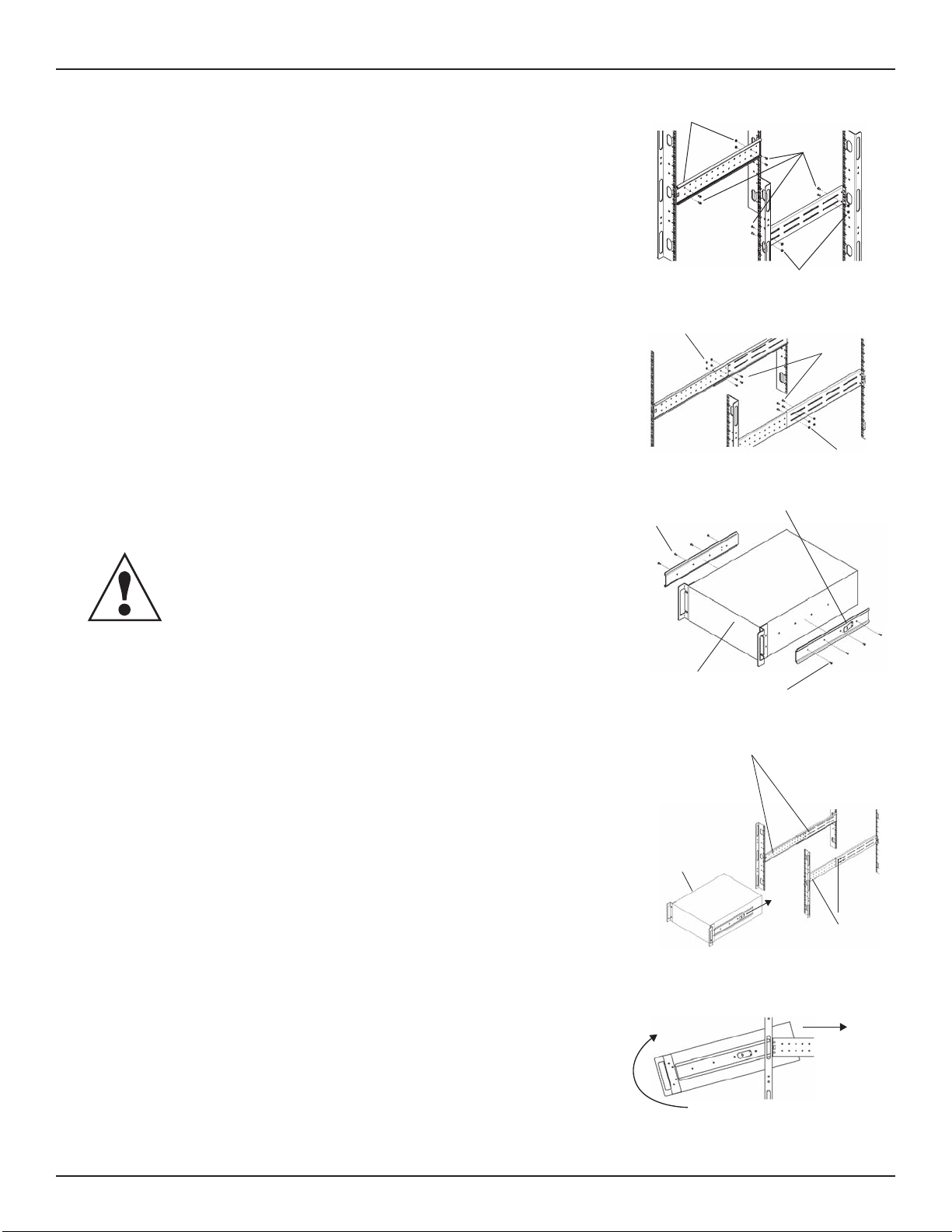
Installation and Conguration
4.Geteight(8)M4screwsandeight(8)M4nutsfromthehardware
packinthiskit.Eachnuthasalocking,nyloninsertthatbegins
grippingthescrewwhenitishalfwaytight.Makesuretotighten
thenutandscrewcompletelytoensurelockingaction.Fasten
therearmemberandthefrontmembertogetherusing(4)screws
and(4)nutsperbracketassemblyasshowninatright.Formaxi-
mumsupport,insertfastenersforeachbracketassemblyasfar
apartaspossible,dependingonrackdepth,whilestilljoiningboth
members(seeguresatright).Checkalignmentofbracket
assembliesandTIGHTENALLSCREWSFROMSteps 2 and 3.
5.PreparetheUPSorbatterycabinet(the“equipment”)forrack
mountingbyfollowinginstructionsintheequipment’suser
manual.Theequipmentmayrequireadditionalpartstobeadded
orpartstoberemovedforrackmounting.Afteritisprepared,
laytheequipmentinrack-mountingposition.Fastentheinner
membersfromStep 1totheequipmentonbothsidesasshown
atrightwitheight(8)M4screwsprovidedinthekit.Makesure
retaininglatchisneartherearoftheequipmentasshown
(seegureatright).
6.Openthegreasepacketprovidedinthekit.Applya1”longbead
ofgreaseatfour(4)placesinsidethebottom,curvedtracksofthe
frontmembersasshownbelowright.Thegreasewillallowthe
equipmenttoslideintothebracketassembliesmoreeasily.
CAUTION
Liftingequipmentintotherackmaybeatwo-personjob,
dependingontheweightoftheequipment.(See
equipment’susermanual.)
7.Inserttheequipment,withinnermembersattachedinStep 5,into
thebracketassembliesbyinsertingthetopandbottomedgesof
theinnermembersintothetopandbottomcurvedtracksofthe
frontmembersandslidingtheequipmentintotherack(seegure
atright).Endsofinnermembersaretaperedtoallowtherearof
theequipmenttobeangledupwardbeforeinsertion,if
spaceallows.
Thentherear,bottomedgesoftheinnermemberscanbeplaced
intothefrontedgeofthebottomtracksandthefrontofthe
equipmentcanbetippedupsotheyareleveltoinsertthetop
edgesoftheinnermembersbeforeslidingtheequip-mentinto
therack(seegurebelowright).Theequipmentshouldmove
smoothlyintothebracketassemblies.Ifitdoesnot,recheckthe
alignmentofthefrontandrearmembersfromSteps 2 and 3.
8.Securethefrontoftheequipmenttotherackmountingrailsto
preventtheequipmentfromslidingoutofposition.Ifsecuring
holesareprovidedonthefrontoftheequipmentthatalignwith
thecenterholesonthereturnangeofthefrontmembers,you
canusethefour(4)extraM5screwsprovidedinthekittosecure
theequipment.Otherwise,theequipmentshouldbesecuredto
thefrontoftherackwithfour(4)customer-suppliedfasteners.
M4 Nuts M4
Screws
M4 Nuts
18” Rack
Depth
M4 Nuts M4
Screws
M4 Nuts
32” Rack
Depth
M4 Nuts Retaining Latch
UPS or Battery
Cabinet
Front M4 Screws
UPS or
Battery
Cabinet
Apply
Grease
(inside)
Apply
Grease
...and push it
into the Rack
Insert the UPS into the Front
Members, lift the Front...
12

Installation and Conguration
6.2 External Battery Cabinet Installation
OptionalSola/Hevi-DutyexternalbatterycabinetsmaybeconnectedtotheUPStoprovideadditionalbattery
runtime.ExternalbatterycabinetsaredesignedtobeplacedononesideoftheUPSorstackedbeneath
theUPS.
Theexternalbatterycabinetframeandbatterykitsareshippedseparately.This4Ucabinetarriveswithout
internalbatteriestolightenthecabinetforeasierinstallation.Oncethecabinethasbeenplacedinitsnaloor
orrackposition,theinternalbatteriesmaybeinstalled.
CAUTION
Theexternalbatterycabinet(s)areheavy(see14.0-Specications).Externalbatterycabinetscan
beusedinrack-mountortowerconguration.Takeproperprecautionswhenliftingthem.
CAUTION
VerifythatthebatterycabinetcircuitbreakerisintheOFFposition.Donotenergizethebattery
cabinetatthistime.Wheninstallationiscomplete,youwillbeinstructedtoturnonthecircuitbreaker.
Whentheexternalbatterycabinetisreceived,itshouldbeinspectedforfreightdamage.Reportdamagetothe
carrierandyourlocaldistributororSola/Hevi-Dutyrepresentative.
Toinstallanexternalbatterycabinet:
1.Forsliderailinstallations,rstremovethetopbezel.Optionalrack-mounthandlesareshippedwiththe
externalbatterycabinetandmaybeinstallednow.(Securinghardwareandsliderailsaresoldseparately.
PleasecontactyourlocaldistributororSola/Hevi-Dutyrepresentativefortheseadditionaloptionsandany
assistance needed.)
2.Fastentheslidesintopositionwiththescrewsaccordingtotheinstructionsincludedwiththesliderails.
3.Usetheenclosedsupportbasesforthetoweroptiontopreventtheassemblyfromtippingover.Oneadditional
setofsupportbaseextensionsshipswitheachexternalbatterycabinet.
4.Installthetwobatterypacksandsecurewiththetwobracketssupplied.
5.Connectthetwoslottedbatterycables.
6.Attachthebatterycoverplateandthetwofrontbezels.
7.Connectthesuppliedexternalbatterycabinetcablestoeithersetof
connectorsontherearoftheexternalbatterycabinet,thentotherear
oftheUPS.
8.TheUPSisnowequippedwithadditionalbackupbatteryruntime.
Forapproximatebatteryruntimes,refertoTable 6 - Battery run times
inthismanual.
9.DoNOTturnonthebatterycabinetcircuitbreakeratthistime.
Pleasecompletetheremainderoftheinstallationrst.
Support Base With
Spacers for External
Battery Cabinets
NOTE
UPS automatically detects the number of standard
batteries that are connected. The conguration
program maybe used to setup the UPS for operation
with non-standard external batteries. Instructions for
using the conguration program follow in
8.0 - Conguration Program.
13
UPS and
External Battery Cabinet
+
BATTERY CONNECTORBATTERYCONNECTION
CIRCUIT BREAKER +
++

Installation and Conguration
6.3 Connect Input/Output Power
TheUPShashardwireterminalblocksforinputandoutputelectricalconnections.Optionaloutputdistribution
modulespermitconnectingadditionalloadstotheUPS.Theseoptionalplug-and-playdistributionmodulesoffer
differenttypesandnumbersofconnectionplugs.
14
WARNING
TheUPSmustbecompletelypowereddownbeforebeginningtomaketheseelectricalconnections.
6.3.1 Distribution Module Electrical Connections
ElectricalconnectionsaremadethrougharemovableconduitboxthatattachestotherearoftheUPS.
Theinstallermustprovidea60Abranchcircuitbreaker.Theinputcircuitbreakerandtheoutputcircuitbreakeron
therearxed-paneloftheUPSdisconnectallpowerbetweenthemaincabinetandthedistributionbox.
Themanualbypassswitchpassesutilitypowerdirectlytothebypassswitchfromtheinputterminalblock.The
inputcircuitbreakerdoesnotdisconnectpowerfromthemanualbypassswitch.
Figure 6 60A branch circuit breaker connection diagram
Optional
Output
Distribution
Plate
Utility
Input
60A External
Branch
Circuit Breaker
60A
Input
Circuit
Breaker Output
Terminal
Block
60A
Output
Circuit
Breaker
60A Maintenance
Bypass Breaker
UPS
Input
Indicator Output
Indicator
CAUTION
AdisconnectswitchshallbeprovidedbyothersforACinputcircuit.Toreducetheriskofre,connect
onlytoacircuitprovidedwithbranchcircuitover-currentprotectionfor60amperesratingin
accordancewiththeNationalElectricCode,ANSI/NFPA70.
Table of contents
Other Sola Hevi Duty UPS manuals

Sola Hevi Duty
Sola Hevi Duty S5K User manual

Sola Hevi Duty
Sola Hevi Duty S4K4U6000 User manual

Sola Hevi Duty
Sola Hevi Duty S2K User manual

Sola Hevi Duty
Sola Hevi Duty S1K320 User manual

Sola Hevi Duty
Sola Hevi Duty S4K2U Series User manual

Sola Hevi Duty
Sola Hevi Duty S3K2U User manual

Sola Hevi Duty
Sola Hevi Duty S4K5U6000-5 User manual


