Sola Hevi Duty S4K2U Series User manual

SS4K2U Industrial Online Series UPS
POWER AVAILABILITY
700-3000VA
120V
USER MANUAL


i
TABLE OF CONTENTS
IMPORTANT SAFETY INSTRUCTIONS. . . . . . . . . . . . . . . . . . . . . 1
GLOSSARY OF SYMBOLS . . . . . . . . . . . . . . . . . . . . . . . . . . . . 3
INTRODUCTION . . . . . . . . . . . . . . . . . . . . . . . . . . . . . . . . . . . . 4
MAJOR COMPONENTS. . . . . . . . . . . . . . . . . . . . . . . . . . . . . . . 5
Transient Voltage Surge Suppression (TVSS) and EMI/RFI Filters . . . 5
Rectifier/Power Factor Correction (PFC) Circuit . . . . . . . . . . . . . . . . . . 5
Inverter. . . . . . . . . . . . . . . . . . . . . . . . . . . . . . . . . . . . . . . . . . . . . . . . . . 5
Battery Charger . . . . . . . . . . . . . . . . . . . . . . . . . . . . . . . . . . . . . . . . . . . 6
DC to DC Converter. . . . . . . . . . . . . . . . . . . . . . . . . . . . . . . . . . . . . . . . 6
Battery . . . . . . . . . . . . . . . . . . . . . . . . . . . . . . . . . . . . . . . . . . . . . . . . . . 6
Dynamic Bypass . . . . . . . . . . . . . . . . . . . . . . . . . . . . . . . . . . . . . . . . . . 6
S4K2U Industrial Online Series UPS (Rear View) . . . . . . . . . . . . . . . . 7
INSTALLATION . . . . . . . . . . . . . . . . . . . . . . . . . . . . . . . . . . . . 8
Preparation . . . . . . . . . . . . . . . . . . . . . . . . . . . . . . . . . . . . . . . . . . . . . . 8
Tower UPS Installation . . . . . . . . . . . . . . . . . . . . . . . . . . . . . . . . . . . . . 8
Rack-Mount UPS Conversion and Installation. . . . . . . . . . . . . . . . . . . . 9
External Battery Cabinet Installation . . . . . . . . . . . . . . . . . . . . . . . . . . 13
CONTROLS AND INDICATORS. . . . . . . . . . . . . . . . . . . . . . . . . 14
ON/Alarm Silence/Manual Battery Test Button . . . . . . . . . . . . . . . . . . 14
OFF/Bypass Button . . . . . . . . . . . . . . . . . . . . . . . . . . . . . . . . . . . . . . 15
Load/Battery Level Indicators (4 Green, 1 Amber) . . . . . . . . . . . . . . . 15
Fault Indicator LED (Red) . . . . . . . . . . . . . . . . . . . . . . . . . . . . . . . . . . 15
Bypass Indicator LED (Amber) . . . . . . . . . . . . . . . . . . . . . . . . . . . . . . 15
UPS ON Indicator LED (Green) . . . . . . . . . . . . . . . . . . . . . . . . . . . . . . 15
Battery Indicator LED (Amber). . . . . . . . . . . . . . . . . . . . . . . . . . . . . . . 15
AC Input Indicator LED (Green). . . . . . . . . . . . . . . . . . . . . . . . . . . . . . 15
Output Voltage Selection . . . . . . . . . . . . . . . . . . . . . . . . . . . . . . . . . . . 16
OPERATING INSTRUCTIONS . . . . . . . . . . . . . . . . . . . . . . . . . . 17
Normal Mode Operation. . . . . . . . . . . . . . . . . . . . . . . . . . . . . . . . . . . . 17
Battery Mode Operation. . . . . . . . . . . . . . . . . . . . . . . . . . . . . . . . . . . . 17
Battery Recharge Mode . . . . . . . . . . . . . . . . . . . . . . . . . . . . . . . . . . . . 17

ii
COMMUNICATIONS . . . . . . . . . . . . . . . . . . . . . . . . . . . . . . . . 18
Communications Interface Port . . . . . . . . . . . . . . . . . . . . . . . . . . . . . . 18
Pin 4 - Remote Shutdown on Battery. . . . . . . . . . . . . . . . . . . . . . . . . . 18
UPS Intelligent Communications. . . . . . . . . . . . . . . . . . . . . . . . . . . . . .19
CONFIGURATION PROGRAM . . . . . . . . . . . . . . . . . . . . . . . . 21
S4K2U UPS Configuration Program Abilities . . . . . . . . . . . . . . . . . . . . 21
What You Will Need . . . . . . . . . . . . . . . . . . . . . . . . . . . . . . . . . . . . . . . 21
MAINTENANCE . . . . . . . . . . . . . . . . . . . . . . . . . . . . . . . . . . . 22
Battery Replacement. . . . . . . . . . . . . . . . . . . . . . . . . . . . . . . . . . . . . . 22
Internal Battery Replacement Procedures . . . . . . . . . . . . . . . . . . . . . . 23
Fuse Replacement. . . . . . . . . . . . . . . . . . . . . . . . . . . . . . . . . . . . . . . . .24
TROUBLESHOOTING . . . . . . . . . . . . . . . . . . . . . . . . . . . . . . 25
SPECIFICATIONS. . . . . . . . . . . . . . . . . . . . . . . . . . . . . . . . . . 30
BATTERY CABINET SPECIFICATIONS . . . . . . . . . . . . . . . . 32
BATTERY RUN TIMES . . . . . . . . . . . . . . . . . . . . . . . . . . . . . . 33
PRODUCT REGISTRATION AND
WARRANTY & SOFTWARE INFORMATION . . . . . . . . . . . . 34

1
IMPORTANT SAFETY INSTRUCTIONS
SAVE THESE INSTRUCTIONS
This manual contains important safety instructions. Read all safety,
installation, and operating instructions before operating the
Uninterruptible Power System (UPS). Adhere to all warnings on the unit
and in this manual. Follow all operating and user instructions. Individuals
without previous training can install and operate this equipment.
It is not intended for use with life support and other designated “critical”
devices. Maximum load must not exceed that shown on the UPS rating
label. The UPS is designed for data processing equipment. If uncertain,
consult your local distributor or Sola/Hevi-Duty representative.
This UPS is designed for use on a properly grounded (earthed),
100-127 VAC, 50 Hz or 60 Hz supply.
ELECTROMAGNETIC COMPATIBILITY—The S4K2U Industrial Online
Series UPS complies with the limits for a CLASS A DIGITAL DEVICE,
PURSUANT TO Part 15 of FCC rules. Operation is subject to the
following two conditions: (1) This device may not cause harmful
interference, and (2) this device must accept any interference received,
including interference that may cause undesired operation. Operating this
device in a residential area is likely to cause harmful interference that
users must correct at their own expense.
Operate the UPS in an indoor environment only in an ambient
temperature range of 32°F to +104°F (0°C to +40°C). Install it in a clean
environment, free from moisture, flammable liquids, gases and
corrosive substances.
!WARNING
OPENING OR REMOVING THE COVER MAY EXPOSE
YOU TO LETHAL VOLTAGES WITHIN THIS UNIT
EVEN WHEN IT IS APPARENTLY NOT OPERATING
AND THE INPUT WIRING IS DISCONNECTED FROM
THE ELECTRICAL SOURCE. OBSERVE ALL
CAUTIONS AND WARNINGS IN THIS MANUAL.
FAILURE TO DO SO MAY RESULT IN SERIOUS
INJURY OR DEATH. REFER ALL UPS AND BATTERY
SERVICE TO QUALIFIED SERVICE PERSONNEL. DO
NOT ATTEMPT TO SERVICE THIS PRODUCT
YOURSELF. NEVER WORK ALONE.

2
This UPS contains no user serviceable parts except the internal battery
packs and the rear input line fuses. The UPS ON/Standby push buttons
do not electrically isolate internal parts. Under no circumstances attempt
to gain access internally other than to replace the batteries due to risk of
electric shock or burn. Do not continue to use the UPS if the front panel
indications are not in accordance with these operating instructions or if
the UPS performance alters in use. Refer all faults to your local
distributor, Sola/Hevi-Duty representative or Sola/Hevi-Duty Technical
Support Group.
Servicing of batteries should be performed or supervised by personnel
knowledgeable of batteries and the required precautions. Keep
unauthorized personnel away from the batteries. PROPER DISPOSAL
OF BATTERIES IS REQUIRED. REFER TO YOUR LOCAL LAWS AND
REGULATIONS FOR BATTERY DISPOSAL REQUIREMENTS.
Never block or insert any object into the ventilation holes or other
openings of the UPS.
DO NOT CONNECT equipment that could overload the UPS or demand
DC current from the UPS, for example: electric drills, vacuum cleaners,
laser printers, hair dryers or any appliance using half-wave rectification.
Storing magnetic media on top of the UPS may result in data loss
or corruption.
Turn the UPS off and isolate the UPS before cleaning; use only a soft
cloth, never liquid or aerosol cleaners. Keep the front and rear vents free
of dust accumulation that could restrict airflow.
When replacing batteries, replace with the same Sola/Hevi-Duty
authorized replacement battery kits.
!CAUTION
Do not dispose of battery or batteries in a fire. The
battery may explode.
Do not open or mutilate the battery or batteries.
Released electrolyte is harmful to skin and eyes. It
may be toxic.
!CAUTION
A battery can present a risk of electrical shock and
high short circuit current. The following precautions
should be observed when working on batteries:
• Remove watches, rings, or other metal objects.
• Use tools with insulated handles.
3
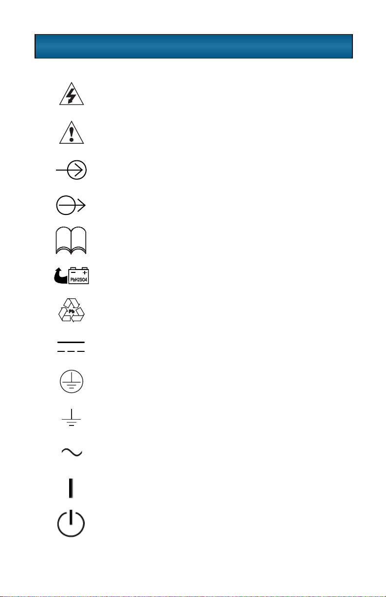
GLOSSARY OF SYMBOLS
•
Risk of electrical shock
Indicates caution followed by important instructions
AC input
AC output
Requests the user to consult the manual
Indicates the unit contains a valve-regulated lead acid
battery
Recycle
DC voltage
Equipment grounding conductor
Bonded to ground
AC voltage
ON
Standby
i

4
INTRODUCTION
Congratulations on your choice of the Sola/Hevi-Duty S4K2U Industrial
Online Series Uninterruptible Power System (UPS). It provides conditioned
power to microcomputers and other sensitive electronic equipment.
Upon generation, AC power is clean and stable. However, during
transmission and distribution it may be subject to voltage sags, spikes, or
complete power failure that may interrupt computer operations, cause
data loss, or even damage equipment. The S4K Industrial UPS protects
equipment from these disturbances.
The S4K2U comes in nominal power ratings of 700, 1000,
1500, 2000 and 3000 VA. Complete model specifications appear at the
end of this manual.
The S4K2U is a compact, “on-line” UPS. An on-line UPS
continuously conditions and regulates its output voltage, whether utility
power is present or not. It supplies connected equipment with clean
sinewave power. Sensitive electronic equipment operates best from
sinewave power.
For ease of use, the S4K2U UPS features a light-emitting diode
(LED) display to indicate either load percentage or battery capacity
depending upon the mode of operation. It also provides self-diagnostic
tests, a combination On/Alarm Silence/Manual Battery Test button, a
Standby button, user configurable program, and two levels of alarms
when the unit is operating on battery.
The S4K2U UPS has an interface port for communication between
the UPS and a network server or other computer systems. This port
provides detailed operating information including voltages, currents, and
alarm status to the host system when used in conjunction with
MultiLink™software. MultiLink software can also remotely control
UPS operation.
5
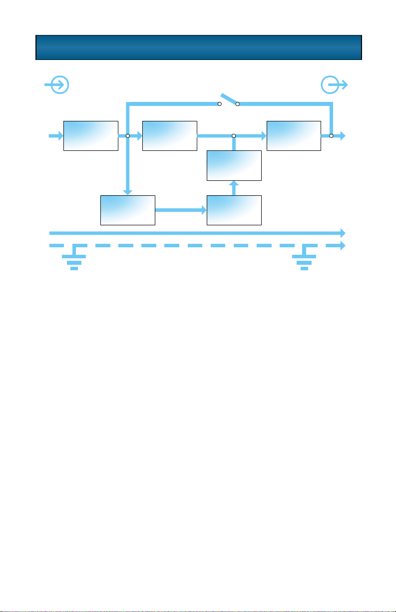
MAJOR COMPONENTS
TRANSIENT VOLTAGE SURGE SUPPRESSION (TVSS) AND EMI/RFI
FILTERS
These UPS components provide surge protection and filter both
electromagnetic interference (EMI) and radio frequency interference
(RFI). They minimize any surges or interference present in the utility line
and keep the sensitive equipment protected.
RECTIFIER/POWER FACTOR CORRECTION (PFC) CIRCUIT
In normal operation, the rectifier/power factor correction (PFC) circuit
converts utility AC power to regulated DC power for use by the inverter
while ensuring that the waveshape of the input current used by the UPS is
near ideal. Extracting this sinewave input current achieves two objectives:
• The utility power is used as efficiently as possible by the UPS.
• The amount of distortion reflected on the utility is reduced.
This results in cleaner power being available to other devices in the
building not being protected by the S4K2U UPS.
INVERTER
In normal operation, the inverter utilizes the DC output of the power factor
correction circuit and inverts it into precise, regulated sinewave AC power.
Upon a utility power failure, the inverter receives its required energy from
the battery through the DC to DC converter. In both modes of operation,
the UPS inverter is on-line and continuously generating clean, precise,
regulated AC output power.
Input Output
Inverter
Battery
Battery
Charger
DC to DC
Converter
Rectifier
/PFC
TVSS &
EMI/RFI
Filters
L
N
G
L
N
G
Dynamic
Bypass

6
BATTERY CHARGER
The battery charger utilizes energy from the utility power and precisely
regulates it to continuously “float charge” the batteries. The batteries are
being charged whenever the S4K2U UPS is plugged in, even when the
UPS is not turned on.
DC TO DC CONVERTER
The DC to DC converter utilizes energy from the battery system and
raises the DC voltage to the optimum operating voltage for the inverter.
This allows the inverter to operate continuously at its optimum efficiency
and voltage, thus increasing reliability.
BATTERY
The S4K2U UPS utilizes valve-regulated, nonspillable, flame
retardant, lead acid batteries. To maintain battery design life, operate the
UPS in an ambient temperature of 68°F to 77°F (20°C to 25°C). Optional
external battery cabinets are available to extend battery run times.
DYNAMIC BYPASS
The S4K2U UPS provides an alternate path for utility power to the
connected load in the unlikely event of a UPS malfunction. Should the
UPS have an overload, overtemperature, or UPS failure condition, the
UPS automatically transfers the connected load to bypass. Bypass
operation is indicated by an alarm and illuminated Bypass LED (other
LEDs may be illuminated to indicate the diagnosed problem). To manually
transfer the connected load from the inverter to bypass, press the
Standby button once.
NOTE
The bypass power path does NOT protect the connected
equipment from disturbances on the utility supply.
7
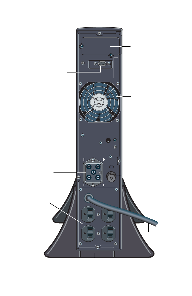
S4K2U INDUSTRIAL Online Series UPS (REAR VIEW)
Input Fuse/Circuit
Breaker
AC Input
Support Base
Output
Receptacles
External Battery
Connector
Cooling Fan
Intellislot®Port
DB-9
Communications Port
8
INSTALLATION
PREPARATION
1. Visually inspect the UPS for freight damage. Report damage to the
carrier and your local distributor or Sola/Hevi-Duty representative.
2. Decide where to place the S4K2U UPS. Install the UPS
indoors in a controlled environment, where it cannot be accidentally
turned off. Place it in an area of unrestricted airflow around the unit,
away from water, flammable liquids, gases, corrosives, and
conductive contaminants. Maintain a minimum clearance of 4 inches
(100mm) in the front and rear of the UPS. Maintain an ambient
temperature range of 32°F to 104°F (0°C to 40°C).
3. The S4K2U UPS may be installed in either a tower
configuration or in a rack, depending on available space and use
considerations. Determine the type of installation and follow the
appropriate instructions in either Tower UPS Installation or
Rack-Mount UPS Conversion and Installation.
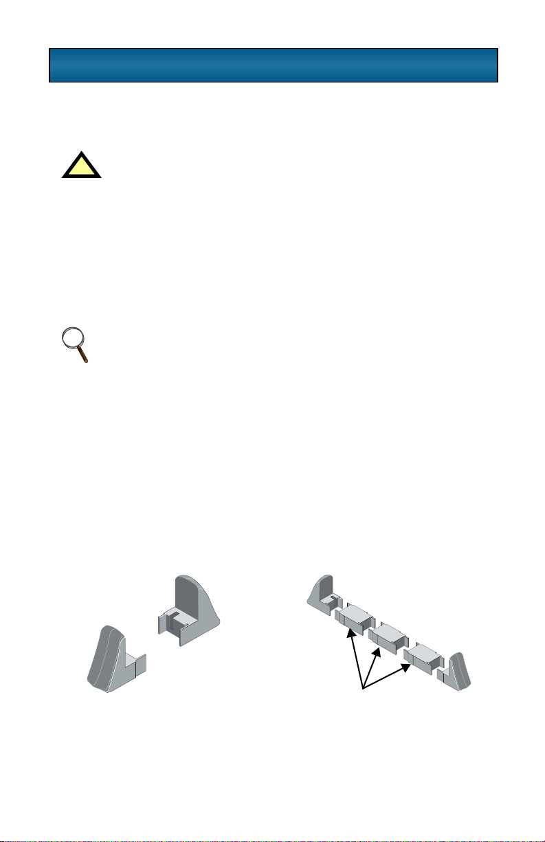
TOWER UPS INSTALLATION
When using the S4K2U UPS in a tower configuration, use the
included support base (shown below, left) to stabilize the UPS.
If any battery cabinets are added, they will include spacers to
accommodate the additional cabinets (shown below, right).
!CAUTION
The UPS is heavy (see Specifications section). Take
proper precautions when lifting or moving it.
NOTE
UPS operation in temperatures above 77°F (25°C) reduces
battery life.
Support base Spacers added to support
base to accommodate
additional battery cabinets

9
RACK-MOUNT UPS CONVERSION AND INSTALLATION
1. For slide rail installations, first remove the top/side fin. Slide the
top/side fin forward, then lift it up to remove. If desired, install the optional
rack-mount handles that were shipped with the UPS.
Securing hardware and slide rails are sold separately. Contact your
local distributor or Sola/Hevi-Duty representative for these additional
options and any assistance needed.
2. Unpack the two rack-
mounting bracket assemblies
and mounting hardware.
Tfrom the rack-mounting kit
(P/N: SRS1832) assemblies are
interchangeable between
left-hand or right-hand.
Remove the inner member
of each bracket assembly as
shown at right by extending it
to its outermost position,
depressing the retaining
latch and then pulling
the inner member from the
bracket assembly.
NOTE
When rack-mounted, the UPS must be supported by a shelf,
brackets or slide rails on each side. The rack-mount handles
WILL NOT support the weight of the UPS. They are used to
move the UPS into and out of the rack.
BYPASS
UPSON
BATTERY
ACINPUT
SOLA
S4K Industrial UPS
!
-+
Optional rack mount handles
10
3. Determine the height position inside the rack enclosure where you want
to mount the UPS or battery cabinet.
Install rear member of each
bracket assembly into rack
enclosure with two (2) M5
screws provided in this kit.
(See figure at right.) Return
flanges on bracket assembly
fit to the inside of rack
mounting rails. Insert
screws loosely (finger-tight)
into top and bottom holes of
return flange on rear member.
Extend bracket assembly by
sliding front member
forward until it touches the front rack mounting rail. Insert two (2) M5
screws loosely (finger-tight_ into top and bottom holes of return flange
on each front member. Make sure bracket assemblies are at the same
mounting height on all four (4) rack mounting rails.
CAUTION
Re duce risk of tipping the rack enclosure by placing UPS or
battery cabinet in the lowest possible rack position.
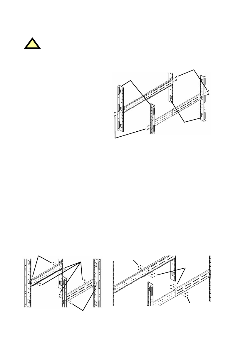
4. Locate eight (8) M4 screws and eight (8) M4 nuts from hardware pack
in this kit. Each nut has a locking, nylon insert that begins gripping the
screw when it is halfway tight. Make sure to tighten nut and screw
completely to assure locking action. Fasten rear member and front member
together using four (4) screws and four (4) nuts per bracket assembly as
shown in the figures below. For maximum support, locate fasteners for
each bracket assembly as far apart as possible, depending on rack depth,
while still joining both members (See figures below). Check alignment of
bracket assemblies and TIGHTEN ALL SCREWS FROM Steps 3 and 4.
!
Front Rack
Mounting Rails
Rear Rack
Mounting
Rails
32” Rack
Depth
M4 Nuts
M4 Nuts
M4
Screws
18”
Rack
Depth
M4 Nuts
M4 Nuts
M4
Screws

11
5. Prepare the UPS or battery
cabinet (the “equipment”) for
rack mounting by following
instructions in the equipment’s
user manual. The equipment
may require additional parts to
be added or parts to be removed
for rack mounting. After it is
prepared, lay equipment on both
sides as shown in the figure at
right with (8) M4 screws provided
in this kit. Make sure retaining latch is
near the rear of the equipment as shown in the figure at right.
6. Open grease packet
provided in this kit. Apply
a 1” long bead of grease four
(4) places inside the bottom,
curved tracks of front
members as shown at right.
The grease will allow the
equipment to slide into the
bracket assemblies more easily.
7. Insert the equipment, with inner members attached from Step 5,
into bracket assemblies by inserting top and bottom edges of inner
members into the top and bottom, curved tracks of front members
and sliding the equipment into rack (see figure in Step 6). Ends of
inner members are tapered to allow rear of the equipment to be
angled upward before insertion, if space allows.
Then the rear, bottoms edges of inner
members can be placed into front
the equipment can be tipped up into
horizontal position to insert the top
edges of inner members before sliding
the equipment into rack (see figure at right).
The equipment should move smoothly into bracket assemblies. If not,
recheck alignment of front and rear members from Steps 3 and 4.
!
UPS or Battery
Cabinet
Front
M4 Screws
M4 Screws
Retaining Latch
UPS or
Battery
Cabinet
Apply
Grease
(inside)
Apply
Grease
!CAUTION
Lifing equipment into rack may be a two-person job,
depending on weight of equipment. See equipment’s
user manual.

12
8. Secure front of the equipment to rack mounting rails to prevent
the equipment from sliding out of position. If securing holes are
provided on front of the equipment that align with the center holes
on return flange of front members, you can use the four (4) extra
M5 screws provided in this kit to secure the equipment.
Otherwise, the equipment should be secured to front of rack
mounting rails with four (4) customer-supplied fasteners.
9. To orient the display for horizonatal
viewing, remove the front plastic
bezel by pulling forward evenly on
both sides. The unit has two front
panel overlays. Remove the outer
overlay (used for tower installation).
This reveals a horizontally oriented front
panel overlay for rack mounting.
Snap the front bezel back into place.
10. Once the UPS is installed in
the rack, the load may be
connected. Ensure the load
equipment is turned off; plug
all loads into the output sockets
on the rear of the UPS.
11. The input supply cable should
be connected to the electrical
supply distribution in accordance
with local rules and conditions.
12. Turn ON the UPS by pressing the
button; then turn on the connected load equipment. The UPS is now
providing conditioned power to your equipment.
BYPASS
UPSON
BATTERY
ACINPUT
SOLA
S4KIndustrial UPS
!
-+
BYPASS
UPSON
BATTERY
ACINPUT
SOLA
S4KIndustrial UPS
!
-+
Vertical
overlay
for
tower
UPS
Horizontal overlay
for rack UPS
13
EXTERNAL BATTERY CABINET INSTALLATION
Optional Sola/Hevi-Duty external battery cabinets may be connected to
the UPS to provide additional battery run time. External battery cabinets
are designed to be placed all on one side of the UPS or stacked beneath
the UPS. There is no limit to the number of external battery cabinets that
can be used but each cabinet will increase the battery recharge time.
1. Visually inspect the external battery cabinet for freight damage. Report
damage to the carrier and your local distributor or
Sola/Hevi-Duty representative.
2. For slide rail installations, first remove the top/side fin. Top/side fin
slides forward and then lift up to remove. Optional rack-mount
handles are shipped with the external battery cabinet and may be
installed at this time if desired.
3. Securing hardware and slide rails are sold separately. Please contact
your local distributor or Sola/Hevi-Duty representative for these
additional options and any assistance needed. Fasten the slides into
position with the screws per the instructions included with the slide rails.
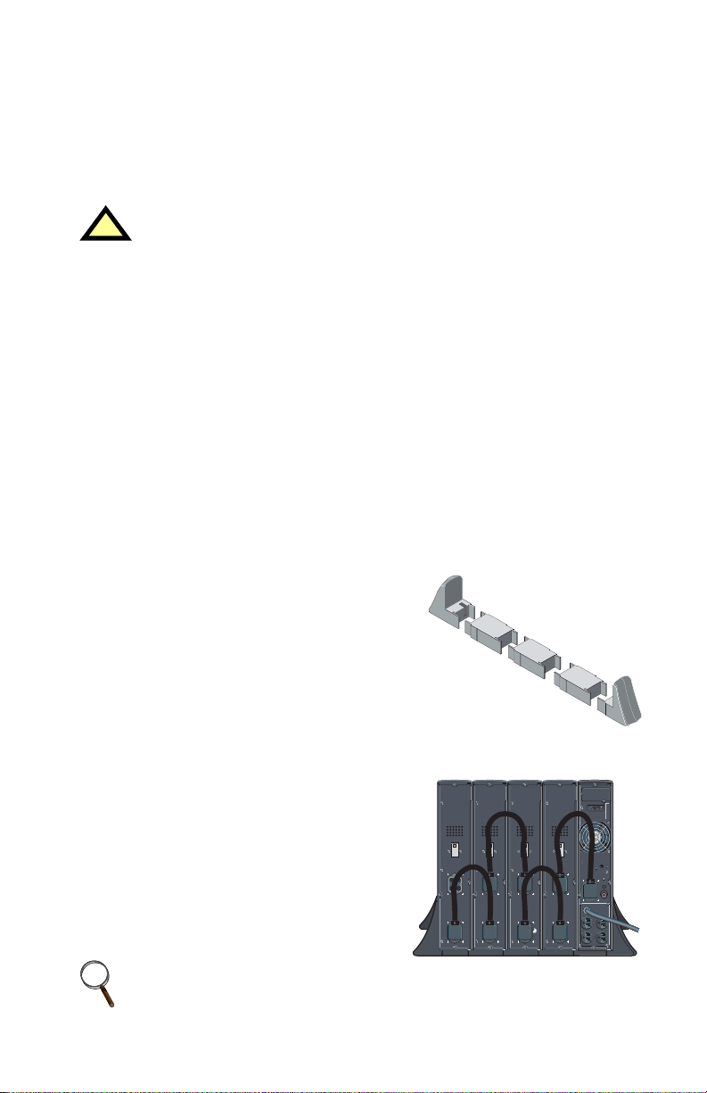
4. Use the enclosed support bases for the
tower option to prevent tip-over. One
additional set of support base
extensions ships with each external
battery cabinet.
5. Connect the supplied external battery
cabinet cable to the rear of the external
battery cabinet, then to the rear of
the UPS.
6. Turn the battery breaker on the rear of
the external battery cabinet “ON”.
7. The UPS is now equipped with
additional backup battery runtime. For
approximate battery runtimes refer to
the Battery Run Times charts in
this manual.
!CAUTION
The external battery cabinet(s) are heavy (see
Specifications section). External battery cabinets can
be used in rack-mount or tower configuration. Take
proper precautions when lifting them.
NOTE
You must use the included Configuration Program to program
the UPS for the number of external battery cabinets connected.

14
CONTROLS AND INDICATORS
ON/Alarm Silence/Manual Battery Test Button
This button controls output power to connected load(s) and has
three functions:
•ON
• Alarm Silence
• Manual Battery Test
ON - Pressing this button will start up the UPS in order to provide
conditioned and protected power.
Alarm Silence - To silence alarms, press this button for at least one
second. After the alarm is silenced, the S4K2U UPS will reactivate
the alarm system to alert of additional problems.
Manual Battery Test - To initiate a manual battery test, press the ON
button for at least one second while operating from utility power with no
alarm conditions present.
• If only three of the five battery LEDs illuminate, allow the UPS to
recharge the batteries for 24 hours.
• After 24 hours, retest the batteries.
• After the batteries have been retested, if only three of the five battery
LEDs illuminate, contact your local distributor, Sola/Hevi-Duty
representative or Sola/Hevi-Duty Technical Support Group.
NOTE
The LOW BATTERY and BYPASS reminder alarms
CANNOT be silenced.
All LEDs illuminated
for illustrative purposes only.

15
OFF/Bypass Button
This button controls output power to connected load(s) and has
dual functions: OFF and Bypass.
Load/Battery Level Indicators (4 Green, 1 Amber)
The Load/Battery Level indicators have dual functions. During normal
mode operation LED indicators display the approximate electrical load
placed upon the UPS; and during battery mode operation LED indicators
display approximate battery capacity.
The S4K2U UPS is equipped with automatic and remote battery
test features. The automatic test occurs every 14 days (this option is user
configurable) if utility has not been interrupted. Should the battery fail this
test, the red Fault indicator LED along with the A and C diagnostic LEDs
will illuminate and an alarm will sound (refer to Troubleshooting section).
The remote test feature functions with MultiLink™3 software and can
remotely initiate the battery test.
Fault Indicator LED (Red)
The Fault indicator LED is illuminated if the UPS has detected a problem.
Also, one or more of the load/battery level indicators may be illuminated
(refer to Troubleshooting section).
Bypass Indicator LED (Amber)
The Bypass indicator LED is illuminated when the UPS is operating from
bypass power. An alarm will sound indicating the UPS detected a
problem, or the manual bypass function has been activated.
UPS ON Indicator LED (Green)
The UPS ON indicator LED is illuminated when the UPS inverter is
operating and supplying power to your connected loads.
Battery Indicator LED (Amber)
The Battery indicator LED is illuminated when the UPS is operating
on battery.
AC Input Indicator LED (Green)
The AC Input indicator LED is illuminated when utility power is available
and within the input specifications.
!CAUTION
Pressing the OFF/Bypass button once will cause the load to be
transferred to bypass power. Once in Bypass pressing the
OFF/Bypass button two times within 4 seconds will turn the
UPS off. This will result in a loss of power to the receptacles
and connected loads, but the UPS's circuits remain live,
charging the units battery. Perform all necessary shutdown
procedures on connected loads before pressing this button.

16
Output Voltage Selection
The Output Voltage is user configurable, and is designed to allow
selecting or changing the desired output voltage to match the utility via
the S4K2U Configuration Program provided with the UPS. The settings to
choose from are 100, 110, 115, 120, and 127 VAC output. The factory
default setting is 120 VAC.
!CAUTION
Never change the voltage settings while the UPS is ON
and powering connected loads.
NOTE
Setting output voltage to 100 VAC will cause the UPS unit to
be derated (700/1000 VA to 90%, 1500/2000/3000 VA to
80%) of the VA and Watt ratings listed in the Specifications
section.
This manual suits for next models
5
Table of contents
Other Sola Hevi Duty UPS manuals

Sola Hevi Duty
Sola Hevi Duty S1K320 User manual

Sola Hevi Duty
Sola Hevi Duty S2K User manual

Sola Hevi Duty
Sola Hevi Duty S4K4U6000 User manual

Sola Hevi Duty
Sola Hevi Duty S5K User manual

Sola Hevi Duty
Sola Hevi Duty S3K2U User manual

Sola Hevi Duty
Sola Hevi Duty S4K6U10000 User manual

Sola Hevi Duty
Sola Hevi Duty S4K5U6000-5 User manual


