Sola Hevi Duty S4K5U6000-5 User manual

POWER AVAILABILITY
S4K5U6000-5 USER MANUAL
On-Line UPS
230VAC
Para español, consulte www.solaheviduty.com/products/ups/UPSmanuals.htm.
Die deutsche Fassung finden Sie auf www.solaheviduty.com/products/ups/UPSmanuals.htm.


i
TABLE OF CONTENTS
IMPORTANT SAFETY INSTRUCTIONS . . . . . . . . . . . . . . . . . . . . . . . . . . . . . . . . . . . . . . . . . . . . . . . .1
WICHTIGE SICHERHEITSANWEISUNGEN. . . . . . . . . . . . . . . . . . . . . . . . . . . . . . . . . . . . . . . . . . . . . .2
GLOSSARY OFSYMBOLS . . . . . . . . . . . . . . . . . . . . . . . . . . . . . . . . . . . . . . . . . . . . . . . . . . . . . . .3
1.0 INTRODUCTION . . . . . . . . . . . . . . . . . . . . . . . . . . . . . . . . . . . . . . . . . . . . . . . . . . . . . . . . . .4
2.0 SYSTEM DESCRIPTION . . . . . . . . . . . . . . . . . . . . . . . . . . . . . . . . . . . . . . . . . . . . . . . . . . . .5
2.1 Transient Voltage Surge Suppression (TVSS) and EMI/RFI Filters. . . . . . . . . . . . . . . . . . . . 5
2.2 Rectifier/Power Factor Correction (PFC) Circuit . . . . . . . . . . . . . . . . . . . . . . . . . . . . . . . . . . . 5
2.3 Inverter . . . . . . . . . . . . . . . . . . . . . . . . . . . . . . . . . . . . . . . . . . . . . . . . . . . . . . . . . . . . . . . . . . . . 5
2.4 Battery Charger . . . . . . . . . . . . . . . . . . . . . . . . . . . . . . . . . . . . . . . . . . . . . . . . . . . . . . . . . . . . . 5
2.5 DC-to-DC Converter. . . . . . . . . . . . . . . . . . . . . . . . . . . . . . . . . . . . . . . . . . . . . . . . . . . . . . . . . . 6
2.6 Battery . . . . . . . . . . . . . . . . . . . . . . . . . . . . . . . . . . . . . . . . . . . . . . . . . . . . . . . . . . . . . . . . . . . . 6
2.7 Dynamic Bypass . . . . . . . . . . . . . . . . . . . . . . . . . . . . . . . . . . . . . . . . . . . . . . . . . . . . . . . . . . . . . 6
3.0 MAJOR COMPONENTS . . . . . . . . . . . . . . . . . . . . . . . . . . . . . . . . . . . . . . . . . . . . . . . . . . . .7
3.1 Main Frame and Electronics . . . . . . . . . . . . . . . . . . . . . . . . . . . . . . . . . . . . . . . . . . . . . . . . . . . 7
3.2 Internal Battery Packs. . . . . . . . . . . . . . . . . . . . . . . . . . . . . . . . . . . . . . . . . . . . . . . . . . . . . . . . 8
3.3 Removable Power Distribution Box. . . . . . . . . . . . . . . . . . . . . . . . . . . . . . . . . . . . . . . . . . . . . . 9
4.0 WHAT’SINCLUDED . . . . . . . . . . . . . . . . . . . . . . . . . . . . . . . . . . . . . . . . . . . . . . . . . . . . . .10
5.0 INSTALLATION AND CONFIGURATION . . . . . . . . . . . . . . . . . . . . . . . . . . . . . . . . . . . . . . . . .11
5.1 Install the Main Cabinet . . . . . . . . . . . . . . . . . . . . . . . . . . . . . . . . . . . . . . . . . . . . . . . . . . . . . 11
5.1.1 Tower UPS Installation . . . . . . . . . . . . . . . . . . . . . . . . . . . . . . . . . . . . . . . . . . . . . . . . . . . . . . . 11
5.1.2 Rack-Mount UPS Installation . . . . . . . . . . . . . . . . . . . . . . . . . . . . . . . . . . . . . . . . . . . . . . . . . . 11
5.1.3 Installing the Adjustable Rack-Mount Kit—Sold Separately . . . . . . . . . . . . . . . . . . . . . . . . . 12
5.2 External Battery Cabinet Installation . . . . . . . . . . . . . . . . . . . . . . . . . . . . . . . . . . . . . . . . . . 14
5.3 Connect the Internal Batteries Using the External Connector. . . . . . . . . . . . . . . . . . . . . . . 15
5.3.1 Storage . . . . . . . . . . . . . . . . . . . . . . . . . . . . . . . . . . . . . . . . . . . . . . . . . . . . . . . . . . . . . . . . . . . . 15
5.4 Connect Input/Output Power. . . . . . . . . . . . . . . . . . . . . . . . . . . . . . . . . . . . . . . . . . . . . . . . . . 15
5.4.1 Distribution Box Electrical Connections . . . . . . . . . . . . . . . . . . . . . . . . . . . . . . . . . . . . . . . . . . 15
6.0 INITIAL START-UPAND ELECTRICAL CHECKS . . . . . . . . . . . . . . . . . . . . . . . . . . . . . . . . . .17
7.0 CONFIGURATION PROGRAM . . . . . . . . . . . . . . . . . . . . . . . . . . . . . . . . . . . . . . . . . . . . . . .18
7.1 S4K5U6000-5 Configuration Program Features . . . . . . . . . . . . . . . . . . . . . . . . . . . . . . . . . . 18
7.1.1 What You Will Need . . . . . . . . . . . . . . . . . . . . . . . . . . . . . . . . . . . . . . . . . . . . . . . . . . . . . . . . . . 18
8.0 CONTROLS AND INDICATORS. . . . . . . . . . . . . . . . . . . . . . . . . . . . . . . . . . . . . . . . . . . . . . .19
8.1 ON/Alarm Silence/Manual Battery Test Button . . . . . . . . . . . . . . . . . . . . . . . . . . . . . . . . . . 19
8.2 Standby/Manual Bypass Button . . . . . . . . . . . . . . . . . . . . . . . . . . . . . . . . . . . . . . . . . . . . . . . 19
8.3 Load Level Indicators (4 Green, 1 Amber) . . . . . . . . . . . . . . . . . . . . . . . . . . . . . . . . . . . . . . . 20
8.4 Battery Level Indicators (5 Green) . . . . . . . . . . . . . . . . . . . . . . . . . . . . . . . . . . . . . . . . . . . . . 20

ii
8.5 Fault Indicator LED (Red). . . . . . . . . . . . . . . . . . . . . . . . . . . . . . . . . . . . . . . . . . . . . . . . . . . . 20
8.6 Bypass Indicator LED (Amber) . . . . . . . . . . . . . . . . . . . . . . . . . . . . . . . . . . . . . . . . . . . . . . . . 20
8.7 UPS ON Indicator LED (Green) . . . . . . . . . . . . . . . . . . . . . . . . . . . . . . . . . . . . . . . . . . . . . . . 20
8.8 Battery Indicator LED (Amber). . . . . . . . . . . . . . . . . . . . . . . . . . . . . . . . . . . . . . . . . . . . . . . . 20
8.9 AC Input Indicator LED (Green). . . . . . . . . . . . . . . . . . . . . . . . . . . . . . . . . . . . . . . . . . . . . . . 20
9.0 OPERATING INSTRUCTIONS. . . . . . . . . . . . . . . . . . . . . . . . . . . . . . . . . . . . . . . . . . . . . . . .21
9.1 Normal Mode Operation. . . . . . . . . . . . . . . . . . . . . . . . . . . . . . . . . . . . . . . . . . . . . . . . . . . . . . 21
9.2 Battery Mode Operation . . . . . . . . . . . . . . . . . . . . . . . . . . . . . . . . . . . . . . . . . . . . . . . . . . . . . 21
9.3 Bypass Mode Operation . . . . . . . . . . . . . . . . . . . . . . . . . . . . . . . . . . . . . . . . . . . . . . . . . . . . . . 21
9.4 Battery Recharge Mode . . . . . . . . . . . . . . . . . . . . . . . . . . . . . . . . . . . . . . . . . . . . . . . . . . . . . . 21
10.0 COMMUNICATIONS . . . . . . . . . . . . . . . . . . . . . . . . . . . . . . . . . . . . . . . . . . . . . . . . . . . . . .22
10.1 Communications Interface Port. . . . . . . . . . . . . . . . . . . . . . . . . . . . . . . . . . . . . . . . . . . . . . . . 22
10.2 Pin 4 - Remote Shutdown on Battery . . . . . . . . . . . . . . . . . . . . . . . . . . . . . . . . . . . . . . . . . . . 22
10.3 UPS Intelligent Communications . . . . . . . . . . . . . . . . . . . . . . . . . . . . . . . . . . . . . . . . . . . . . . 23
10.4 Remote Emergency Power Off . . . . . . . . . . . . . . . . . . . . . . . . . . . . . . . . . . . . . . . . . . . . . . . . . 24
11.0 MAINTENANCE . . . . . . . . . . . . . . . . . . . . . . . . . . . . . . . . . . . . . . . . . . . . . . . . . . . . . . . . .25
11.1 Internal Battery . . . . . . . . . . . . . . . . . . . . . . . . . . . . . . . . . . . . . . . . . . . . . . . . . . . . . . . . . . . . 25
11.1.1 Internal Battery Replacement . . . . . . . . . . . . . . . . . . . . . . . . . . . . . . . . . . . . . . . . . . . . . . . . . 26
11.2 AC Power Connections . . . . . . . . . . . . . . . . . . . . . . . . . . . . . . . . . . . . . . . . . . . . . . . . . . . . . . . 28
11.2.1 S4KPAD-CEHW-MBS - Manual Bypass Switch . . . . . . . . . . . . . . . . . . . . . . . . . . . . . . . . . . . 28
12.0 TROUBLESHOOTING . . . . . . . . . . . . . . . . . . . . . . . . . . . . . . . . . . . . . . . . . . . . . . . . . . . . .29
12.0.1 Auto-Learning Battery Run Times . . . . . . . . . . . . . . . . . . . . . . . . . . . . . . . . . . . . . . . . . . . . . . 33
13.0 SPECIFICATIONS (SECHNISCHE DATEN). . . . . . . . . . . . . . . . . . . . . . . . . . . . . . . . . . . . . . .34

iii
FIGURES
Figure 1 S4K5U, front view. . . . . . . . . . . . . . . . . . . . . . . . . . . . . . . . . . . . . . . . . . . . . . . . . . . . . . . . . . . . . . . . 7
Figure 2 S4K5U, rear view . . . . . . . . . . . . . . . . . . . . . . . . . . . . . . . . . . . . . . . . . . . . . . . . . . . . . . . . . . . . . . . . 8
Figure 3 Internal battery pack with connector . . . . . . . . . . . . . . . . . . . . . . . . . . . . . . . . . . . . . . . . . . . . . . . . 8
Figure 4 Power distribution boxes, basic, optional . . . . . . . . . . . . . . . . . . . . . . . . . . . . . . . . . . . . . . . . . . . . . 9
Figure 5 Tower-use support bases, spacers for external battery cabinets . . . . . . . . . . . . . . . . . . . . . . . . . . 11
Figure 6 Distribution box electrical connections diagram. . . . . . . . . . . . . . . . . . . . . . . . . . . . . . . . . . . . . . . 16

iv
TABLES
Table 1 Electrical specifications . . . . . . . . . . . . . . . . . . . . . . . . . . . . . . . . . . . . . . . . . . . . . . . . . . . . . . . . . . 16
Table 2 DB-9 pin assignment . . . . . . . . . . . . . . . . . . . . . . . . . . . . . . . . . . . . . . . . . . . . . . . . . . . . . . . . . . . . 22
Table 3 Indicator meanings . . . . . . . . . . . . . . . . . . . . . . . . . . . . . . . . . . . . . . . . . . . . . . . . . . . . . . . . . . . . . . 29
Table 4 Troubleshooting guide . . . . . . . . . . . . . . . . . . . . . . . . . . . . . . . . . . . . . . . . . . . . . . . . . . . . . . . . . . . 30
Table 5 Alarm conditions . . . . . . . . . . . . . . . . . . . . . . . . . . . . . . . . . . . . . . . . . . . . . . . . . . . . . . . . . . . . . . . . 31
Table 6 Battery run times . . . . . . . . . . . . . . . . . . . . . . . . . . . . . . . . . . . . . . . . . . . . . . . . . . . . . . . . . . . . . . . 32
Table 7 UPS specifications. . . . . . . . . . . . . . . . . . . . . . . . . . . . . . . . . . . . . . . . . . . . . . . . . . . . . . . . . . . . . . . 34
Table 8 Power distribution specifications . . . . . . . . . . . . . . . . . . . . . . . . . . . . . . . . . . . . . . . . . . . . . . . . . . . 35
Table 9 External battery cabinet specifications . . . . . . . . . . . . . . . . . . . . . . . . . . . . . . . . . . . . . . . . . . . . . . 35
Table 10 Technische Daten zur USV. . . . . . . . . . . . . . . . . . . . . . . . . . . . . . . . . . . . . . . . . . . . . . . . . . . . . . . . 35
Table 11 Technische Daten zur Stromverteilung. . . . . . . . . . . . . . . . . . . . . . . . . . . . . . . . . . . . . . . . . . . . . . 36
Table 12 Technische Daten zum externen Batteriegehause . . . . . . . . . . . . . . . . . . . . . . . . . . . . . . . . . . . . . 37

1
IMPORTANT SAFETY INSTRUCTIONS
SAVE THESE INSTRUCTIONS
This Manual Contains Important Safety Instructions. Read all safety and operating instructions
before operating the Uninterruptible Power Supply (UPS). Adhere to all warnings on the unit and in
this manual. Follow all operating and user instructions. This equipment can be operated by individu-
als without previous training.
This product is designed for Commercial/Industrial use only. It is not intended for use with life sup-
port and other designated “critical” devices. Maximum load must not exceed that shown on the UPS
rating label. The UPS is designed for data processing equipment. If uncertain, consult your dealer.
See Limited Warranty.
This UPS is designed for use on a properly earthed (grounded), 220-240 VAC (L-N), 50Hz or 60Hz
supply, for installation by qualified personnel. A qualified electrician must review and approve cus-
tomer supplied wiring, circuit breakers, intended loads, and verify correct input, output and earth
connections to ensure compliance with technical standards and local electrical codes of practice.
Installation instructions and warning notices only for use by qualified personnel are located after the
UPS operator instructions in this manual.
ELECTROMAGNETIC COMPATIBILITY—This UPS complies with the requirements of the EMC
Directive 89/336/EEC and the published technical standards. Continued compliance requires installa-
tion in accordance with these instructions and the use of manufacturer approved accessories only.
Operate the UPS in an indoor environment only in an ambient temperature range of 0-40°C
(32-104°F). Install it in a clean environment, free from moisture, flammable liquids, gases and corro-
sive substances.
This UPS contains no user serviceable parts. The UPS ON/OFF push buttons do not electrically iso-
late internal parts. Under no circumstances attempt to gain access internally, due to the risk of elec-
tric shock or burn.
Do not continue to use the UPS if the front panel indications are not in accordance with these operat-
ing instructions, or the UPS performance alters in use. Refer all faults to your dealer.
Only trained engineers authorized by Sola/Hevi-Duty should perform troubleshooting. To replace bat-
teries, refer all servicing to qualified service personnel. Proper disposal of batteries is required. Refer
to your local laws and regulations for disposal requirements.
Never block or insert any object into the ventilation holes or other openings.
DO NOT CONNECT equipment that could overload the UPS or demand DC current from the UPS,
for example: electric drills, vacuum cleaners, laser printers, hairdryers or any appliance using half
wave rectification.
Storing magnetic media on top of the UPS may result in data loss or corruption.
Turn the off UPS and isolate the UPS before cleaning. Use only a soft cloth, never liquid or aerosol
cleaners.
!
WARNING
This UPS should not be supplied from electrical power systems of the “IT” (Impédance à
Terre) type. (IEC 364-ELECTRICAL INSTALLATION OF BUILDINGS)
!
WARNING
This is a product for restricted sales distribution to informed partners. Installation
restrictions or additional measures may be needed to prevent radio interference.

2
WICHTIGE SICHERHEITSANWEISUNGEN
DIESE ANWEISUNGEN AUFBEWAHREN
Dieses Handbuch enthält wichtige Sicherheitsanweisungen. Lesen Sie alle Sicherheits- und Betriebs-
anweisungen, bevor Sie die unterbrechungsfreie Stromversorgung (USV) in Betrieb nehmen.
Beachten Sie alle Warnungen am Gerät und in diesem Handbuch. Befolgen Sie alle Betriebs- und
Benutzeranweisungen. Dieses Gerät kann von ungeschulten Personen betrieben werden.
Dieses Produkt ist nur für den gewerblichen / industriellen Gebrauch bestimmt. Es ist nicht für den
Einsatz mit lebenserhaltenden und sonstigen als „kritisch“ bezeichneten Geräten gedacht. Die
Höchstlast darf den auf dem Leistungsschild der USV aufgeführten Wert nicht überschreiten. Die
USV wurde für Datenverarbeitungsgeräte entwickelt. Wenn Sie sich nicht sicher sind, wenden Sie
sich an Ihren Händler. Siehe beschränkte Garantie.
Diese USV wurde zur Verwendung mit einer ordnungsgemäß geerdeten Stromversorgung mit 220 -
240 V AC und 50 Hz oder 60 Hz ausgelegt und muss von qualifiziertem Personal installiert werden.
Ein qualifizierter Elektriker muss die vom Kunden bereitgestellte Verdrahtung, Schutzschalter und
geplante Belastung überprüfen und genehmigen und sicherstellen, dass Eingänge, Ausgänge und
Erdungsanschlüsse ordnungsgemäß installiert sind, um die Einhaltung der technischen Normen und
örtlichen Elektrovorschriften zu gewährleisten. Die Anweisungen zur Installation und Warnhin-
weise, die nur für qualifiziertes Personal gelten, befinden sich hinter den Bedieneranweisungen in
diesem Handbuch.
ELEKTROMAGNETISCHE VERTRÄGLICHKEIT - Diese USV entspricht den Erfordernissen der
EMC-Richtlinie 89/336/EEC und den veröffentlichten technischen Normen. Eine kontinuierliche Ein-
haltung erfordert die Installation gemäß dieser Anweisungen sowie die Verwendung von ausdrück-
lich vom Hersteller genehmigtem Zubehör.
Die USV darf nur innen in einem Umgebungstemperaturbereich von 0-40 °C (32 °F bis +104 °F)
betrieben werden. Es muss in einer sauberen Umgebung installiert werden, die frei von Feuchtigkeit,
brennbaren Flüssigkeiten, Gasen oder korrodierenden Substanzen ist.
Diese USV enthält keine vom Benutzer zu wartenden Teile. Die EIN/AUS-Drucktasten der USV
haben keine elektrische Isolierungsfunktion bei den internen Komponenten. Auf keinen Fall darf ver-
sucht werden, auf das Innere des Gerätes zuzugreifen, da Sie sich ansonsten dem Risiko eines Strom-
schlags oder von Verbrennungen aussetzen.
Wenn die Anzeige an der Vorderplatte nicht mit diesen Betriebsanweisungen übereinstimmt oder die
Leistung der USV schwankt, darf sie nicht weiter verwendet werden. Melden Sie alle Fehler Ihrem
Händler.
Nur geschulte Techniker, die von Sola/Hevi-Duty entsprechend autorisiert wurden, dürfen eine
Fehlersuche durchführen. Beim Ersetzen von Batterien müssen alle Wartungsmaßnahmen von qual-
ifiziertem Service-Personal durchgeführt werden. Batterien müssen ordnungsgemäß entsorgt wer-
den. Die Anforderungen für die Entsorgung entnehmen Sie bitte den örtlichen Gesetzen und
Vorschriften.
Die Belüftungslöcher und sonstige Öffnungen dürfen auf keinen Fall blockiert werden, und es dürfen
keine Gegenstände in sie gesteckt werden.
ES DÜRFEN KEINE GERÄTE ANGESCHLOSSEN WERDEN, die zu einer Überlastung der USV
führen oder mit Gleichstrom versorgt werden müssen, zum Beispiel: Elektrobohrer, Staubsauger,
Laserdrucker, Föhne oder sonstige Haushaltsgeräte, die Halbwellengleichrichtung verwenden.
Das Lagern von Magnetdatenträgern oben auf der USV kann zu einem Datenverlust oder der Zer-
störung von Daten führen.Vor der Reinigung muss die USV ausgeschaltet und isoliert werden. Es
darf nur ein weiches Tuch, niemals Flüssigkeit oder Aerosol-Reiniger verwendet werden.
!
ACHTUNG
Diese USV sollte nicht durch Stromversorgungssysteme des Typs „IT“ (Impédance à Terre)
gespeist werden. (IEC 364 - ELEKTROINSTALLATION IN GEBÄUDEN)
!
ACHTUNG
Dieses Produkt ist für den eingeschränkten Vertrieb an informierte Partner gedacht. Zur
Verhinderung von Funkstörungen sind eventuell Installationseinschränkungen oder
zusätzliche Maßnahmen erforderlich.

3
GLOSSARY OFSYMBOLS
Risk of electrical shock
Gefahr eines Stromschlags
Indicates caution followed by important instructions
Zeigt einen Vorsichtshinweis an, auf den wichtige
Anweisungen folgen
AC input
Wechselstromeingang
AC output
Wechselstromausgang
Requests the user to consult the manual
Fordert den Benutzer dazu auf, das Handbuch zu konsultieren
Indicates the unit contains a valve-regulated lead acid battery
Gibt an, dass das Gerät über eine Bleisäurebatterie mit
Ventilregelung verfügt
Recycle
Recyling zuführen
DC voltage
Gleichspannung
Equipment grounding conductor
Geräteerdleiter
Bonded to ground
Erdung mit Potentialausgleich
AC voltage
Wechselspannung
ON/Alarm Silence/Battery Test
EIN/Alarm stumm schalten/Batterietest
OFF/Bypass
AUS/Bypass
Indicates the position of a fuse
Zeigt die Position einer Sicherung an
!
i
PbH2SO4
-
+
R

Introduction
4
1.0 INTRODUCTION
Congratulations on your choice of the Sola/Hevi-DutyS4K5U6000-5 Uninterruptible Power System
(UPS). It provides conditioned power to microcomputers and other sensitive electronic equipment.
Upon generation, AC power is clean and stable. However, during transmission and distribution it
may be subject to voltage sags, spikes, or complete power failure that may interrupt computer opera-
tions, cause data loss, or even damage equipment. The S4K5U protects equipment from these distur-
bances.
The S4K5U comes in nominal power ratings of 4500 VA and 6000 VA. Complete model specifications
appear at the end of this manual.
The S4K5U is a compact, on-line UPS. An on-line UPS continuously conditions and regulates its out-
put voltage, whether mains power is present or not. It supplies connected equipment with clean sine-
wave power. Sensitive electronic equipment operates best from sinewave power.
For ease of use, the S4K5U features a light-emitting diode (LED) display to indicate both load per-
centage and battery capacity. It also provides self-diagnostic tests, a combination ON/Alarm Silence/
Manual Battery Test button, a Standby button, user configurable program, and two levels of alarms
when the unit is operating on battery.
The S4K5U has an interface port for communication between the UPS and a network server or other
computer systems. This port provides detailed operating information including voltages, currents,
and alarm status to the host system when used in conjunction with Sola/Hevi-Duty MultiLink™ soft-
ware. MultiLink software can also remotely control UPS operation.

System Description
5
2.0 SYSTEM DESCRIPTION
2.1 Transient Voltage Surge Suppression (TVSS) and EMI/RFI Filters
These UPS components provide surge protection and filter both electromagnetic interference (EMI)
and radio frequency interference (RFI). They minimize any surges or interference present in the
mains line and keep the sensitive equipment protected.
2.2 Rectifier/Power Factor Correction (PFC) Circuit
In normal operation, the rectifier/power factor correction (PFC) circuit converts mains AC power to
regulated DC power for use by the inverter while ensuring that the waveshape of the input current
used by the UPS is near ideal. Extracting this sinewave input current achieves two objectives:
• The mains power is used as efficiently as possible by the UPS.
• The amount of distortion reflected on the mains is reduced.
This results in cleaner power being available to other devices in the building not being protected by
the S4K5U.
2.3 Inverter
In normal operation, the inverter utilizes the DC output of the power factor correction circuit and
inverts it into precise, regulated sinewave AC power. Upon a mains power failure, the inverter
receives its required energy from the battery through the DC to DC converter. In both modes of oper-
ation, the UPS inverter is on-line and continuously generating clean, precise, Regulated Ac Output
Power.
2.4 Battery Charger
The battery charger utilizes energy from the mains power and precisely regulates it to continuously
float charge the batteries. The batteries are being charged whenever the S4K5U is connected to
mains power.
Input Output
Inverter
Battery
Battery
Charger
Rectifier
/PFC
DC-to-DC
Converter
TVSS &
EMI/RFI
Filters
G G
Dynamic
Bypass
L1
N
L1
N

System Description
6
2.5 DC-to-DC Converter
The DC to DC converter utilizes energy from the battery system and raises the DC voltage to the opti-
mum operating voltage for the inverter. This allows the inverter to operate continuously at its opti-
mum efficiency and voltage, thus increasing reliability.
2.6 Battery
The S4K5U utilizes valve-regulated, nonspillable, lead acid batteries. To maintain battery design
life, operate the UPS in an ambient temperature of 20°C to 25°C (68°F to 77°F). Optional external
battery cabinets are available to extend battery run times.
2.7 Dynamic Bypass
The S4K5U provides an alternate path for mains power to the connected load in the unlikely event of
a UPS malfunction. Should the UPS have an overload, overtemperature, or UPS failure condition, the
UPS automatically transfers the connected load to bypass. Bypass operation is indicated by an audi-
ble alarm and illuminated amber Bypass LED (other LEDs may be illuminated to indicate the diag-
nosed problem). To manually transfer the connected load from the inverter to bypass, press the
Standby button once.
NOTE
The bypass power path does NOT protect the connected equipment from disturbances
in the mains supply.

Major Components
7
3.0 MAJOR COMPONENTS
The S4K5U is composed of three major assemblies to provide easier handling, installation, and versa-
tility.
3.1 Main Frame and Electronics
This 5U cabinet is shipped with internal batteries installed and a bypass hardwire distribution box
attached and ready to install.
Figure 1 S4K5U, front view
!
Status
Indicators
& Controls
Battery Access
Bezel
Top Cover
(Tower use
only)
Major Components
8
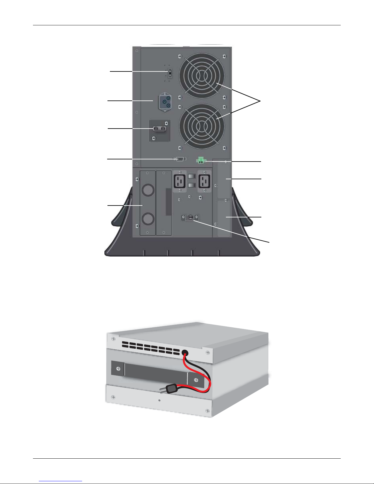
Figure 2 S4K5U, rear view
3.2 Internal Battery Packs
The UPS has two internal battery packs behind a battery access door on the front of the unit. Each
pack is fitted with a connector to link to the UPS.
Figure 3 Internal battery pack with connector
Fans
External Battery
Connector
DB-9
Communication
Port
Removable Power
Distribution Box
Serial Card Slot
(SNMP WEB CARD or
MULTIPORT4CARD)
Relay Card Slot
REPO Connector
UPS Output
Circuit Breaker
Battery
Disconnect
Input Circuit Breaker

Major Components
9
3.3 Removable Power Distribution Box
The UPS arrives with a bypass hardwire power distribution pack installed. This box always contains
the UPS input circuit breaker.
Optional versions may be available to replace the standard box for custom installations.
Figure 4 Power distribution boxes, basic, optional
NOTE
Hardwire and hardwire/receptacle boxes that include a manual bypass switch allow
AC power to continue to flow from the mains input to the load while the box is removed
from the UPS. For details, refer to 11.2 - AC Power Connections.
Optional Hardwire Power Dist. Box
S4KPAD-CEHW Hardwire Power Distribution Box with
Maintenance Bypass Switch
S4KPAD-CEHW-MBS

What’s Included
10
4.0 WHAT’SINCLUDED
The S4K5U are shipped with the following items:
• S4K5U6000-5 user manual
• Vertical display overlay
• MultiLink software CD
• MultiLink serial cable, 10 ft (3m)
• Rack mount handles
• Support base - 2
• Mounting hardware
• Configuration program disk
•DB9portcover
RS232
MultiLink
software CD
Mounting hardware
Vertical
display
Rack mount
handles
MultiLink
serial cable
10 ft (3m)
Configuration
disk
S4K5U ola/
and select Run
Support base
with spacers
DB9 port cover

Installation and Configuration
11
5.0 INSTALLATION AND CONFIGURATION
Do NOT attempt to start the UPS, turn on any circuit breaker or energize the input power until
instructed to do so in 6.0 - Initial Start-Up and Electrical Checks.
Visually inspect the UPS for freight damage. Report any damage to the carrier and your local dealer
or Sola/Hevi-Duty representative.
Install the S4K5U indoors in a controlled environment, where it cannot be accidentally turned off.
Place it where air flows unrestricted around the unit. The installation location must be free of water,
flammable liquids, gases, corrosives and conductive contaminants. Maintain a minimum clearance of
100mm (4 inches) in the front and rear of the UPS. Maintain an ambient temperature range of 0 to
40°C (32 -104°F).
5.1 Install the Main Cabinet
The S4K5U may be installed in either a tower configuration or in a rack, depending on available
space and use considerations. Determine the type of installation and follow the appropriate instruc-
tions in either 5.1.1 - Tower UPS Installation or 5.1.2 - Rack-Mount UPS Installation.
5.1.1 Tower UPS Installation
When using the S4K5U in a tower configuration, use the included support base (shown below, left) to
stabilize the UPS. If any external battery cabinets are added, they will include spacers to accommo-
date the additional cabinets (shown below, right).
Figure 5 Tower-use support bases, spacers for external battery cabinets
5.1.2 Rack-Mount UPS Installation
When using the S4K5U in a rack-mount configuration, the UPS must be supported by a slide kit,
fixed rails or a shelf.
When using the optional Adjustable Rack Mount Kit, you will use the following instructions. The fig-
ures accompanying 5.1.3 - Installing the Adjustable Rack-Mount Kit—Sold Separately shows
the positioning of the rack-mounting brackets. Taking the internal batteries out of the UPS during
rack installation is recommended. This will make the UPS cabinet lighter and easier to handle.
!
CAUTION
The UPS is heavy (see 13.0 - Specifications (Sechnische Daten)). Take
proper precautions when lifting or moving it.
NOTE
UPS operation in sustained temperatures above 25°C (77°F) reduces battery life.
This device is intended for use in an Installation Category II environment.
!
CAUTION
Only three (3) M4 screws are used on the side of the S4K5U where the Power Distribution Box
is located. The fourth mounting hole is above the Power Distribution Box and is not used.
3U
2U 2U
5U support base for S4K5U
End bases and 3U spacer
3U
2U 2U
Spacers added to support base
to accommodate additional battery cabinets
3U

Installation and Configuration
12
5.1.3 Installing the Adjustable Rack-Mount Kit—Sold Separately
This kit contains parts needed to mount several different models of UPS and external battery cabi-
nets into EIA310-D standard four-post racks that are 18-32" deep (457-813mm). The weight limit per
pair of adjustable rack-mounting brackets is 91 kg (200lbs.).
Parts included are:
Tools needed for installation are:
• one Phillips screwdriver
• one 7mm wrench
The adjustable rack-mounting brackets (part # SRS18-32) feature retaining latches to prevent users
from inadvertently sliding the UPS or battery cabinet out of the rack.
To install the rack mount brackets:
1. Unpack two (2) rack-mounting bracket assemblies and
mounting hardware from this kit. Bracket assemblies are
interchangeable between left-hand or right-hand.
Remove inner member of each bracket assembly as shown
at right by extending it to its outermost position, depress-
ing the retaining latch and then pulling the inner member
out of the bracket assembly.
2. Determine the height position inside the rack enclosure
where you want to mount the UPS or battery cabinet.
3. Install the rear member of each bracket assembly into the
rack enclosure with two (2) M5 screws provided in this kit
(see figure at right). The return flanges on the bracket
assembly fit to the inside of rack mounting rails. Insert
screws loosely (finger-tight) into the top and bottom holes of
the return flange on the rear member. Extend the bracket
assembly by sliding the front member forward until it
touches the front rack mounting rail. Insert two (2) M5
screws loosely (finger-tight) into the top and bottom holes of
the return flange on each front member. Make sure that the
bracket assemblies are at the same mounting height on all
four (4) rack mounting rails.
Item Quantity
Rear bracket members 2
Front bracket members 2
Inner bracket members 2
M4 x 8mm machine screws 16
M4 locking hex nuts 8
M5 x 16 mm machine screws 12
Grease packet. 1
!
CAUTION
Reduce the risk of tipping the rack enclosure by
placing the UPS or battery cabinet in the lowest
possible rack position.
Return
flanges
Inner
members
Front
members
Retaining
Latches
M5 screws
M5 screws
Front rack
mounting rails
Rear rack
mounting
rails

Installation and Configuration
13
4. Get eight (8) M4 screws and eight (8) M4 nuts from the
hardware pack in this kit. Each nut has a locking, nylon
insert that begins gripping the screw when it is halfway
tight. Make sure to tighten the nut and screw completely to
ensure locking action. Fasten the rear member and the front
member together using (4) screws and (4) nuts per bracket
assembly as shown in at right. For maximum support, insert
fasteners for each bracket assembly as far apart as possible,
depending on rack depth, while still joining both members
(see figures at right). Check alignment of bracket assemblies
and TIGHTEN ALL SCREWS FROM Steps 2 and 3.
5. Prepare the UPS or battery cabinet (the “equipment”) for
rack mounting by following instructions in the equipment’s
user manual. The equipment may require additional parts to
be added or parts to be removed for rack mounting. After it is
prepared, lay the equipment in rack-mounting position.
Fasten the inner members from Step 1 to the equipment on
both sides as shown at right with eight (8) M4 screws
provided in the kit. Make sure retaining latch is near the rear
of the equipment as shown (see figure at right).
6. Open the grease packet provided in the kit. Apply a bead of
grease 25mm (1") long at four (4) places inside the bottom,
curved tracks of the front members as shown below right. The
grease will allow the equipment to slide into the bracket
assemblies more easily.
7. Insert the equipment, with inner members attached in
Step 5, into the bracket assemblies by inserting the top and
bottom edges of the inner members into the top and bottom
curved tracks of the front members and sliding the
equipment into the rack (see figure at right). Ends of inner
members are tapered to allow the rear of the equipment to be
angled upward before insertion, if space allows.
Then the rear, bottom edges of the inner members can be
placed into the front edge of the bottom tracks and the front
of the equipment can be tipped up so they are level to insert
the top edges of the inner members before sliding the equip-
ment into the rack (see figure below right). The equipment
should move smoothly into the bracket assemblies. If it does
not, recheck the alignment of the front and rear members
from Steps 2 and 3.
8. Secure the front of the equipment to the rack mounting rails
to prevent the equipment from sliding out of position. If
securing holes are provided on the front of the equipment
that align with the center holes on the return flange of the
front members, you can use the four (4) extra M5 screws
provided in the kit to secure the equipment. Otherwise, the
equipment should be secured to the front of the rack with
four (4) customer-supplied fasteners.
!
6.
CAUTION
Lifting equipment into the rack may be a two-person
job, depending on the weight of the equipment. Sola/
Hevi-Duty recommends taking the internal batteries
out of the UPS during rack installation. This will
make the UPS cabinet lighter and easier to handle.
The S4K5U weighs 67kg (151lb). For the battery
cabinet’s weight, see the unit’s user manual.
813mm
(32") rack
depth
M4 nuts
M4 nuts
M4
screws
457mm
(18")
rack
depth
M4 nuts
M4 nuts
M4
screws
UPS or battery
cabinet
Front
M4 screws
M4 screws
Retaining latch
UPS or
battery
cabinet
Apply
grease
(inside)
Apply
grease
Insert the UPS into the front
members, lift the front ...
...andpushit
into the rack.

Installation and Configuration
14
5.2 External Battery Cabinet Installation
Optional Sola/Hevi-Duty external battery cabinets may be connected to the UPS to provide additional
battery run time. External battery cabinets are designed to be placed on one side of the UPS or
stacked beneath the UPS.
1. Visually inspect the external battery cabinet for freight damage. Report damage to the carrier
and your local dealer or Sola/Hevi-Duty representative.
2. For slide rail installations, first remove the top/side fin. Top/side fin slides forward and then lift
up to remove. Optional rack-mount handles are shipped with the external battery cabinet and
may be installed at this time if desired.
3. Securing hardware and slide rails are sold separately. Please contact your local dealer or Sola/
Hevi-Duty representative for these additional options and any assistance needed. Fasten the
slides into position with the screws per the instructions included with the slide rails.
4. Use the enclosed support bases for the tower option to prevent tip-over. One additional set of
support base extensions ships with each external battery cabinet.
5. Connect the supplied external battery cabinet cable to the rear of the external battery cabinet,
then to the rear of the UPS.
6. The UPS is now equipped with additional backup battery run time. For approximate battery run
times, refer to Table 6.
!
CAUTION
The external battery cabinet(s) are heavy (see 13.0 - Specifications (Sechnische Daten)).
External battery cabinets can be used in rack-mount or tower configuration. Take proper
precautions when lifting them.
!
VORSICHT
Externe Batteriegehäuse sind schwer (siehe 13.0 - Specifications (Sechnische Daten)).
Externe Batteriegehäuse können in einer Rack-Montage- oder Turmkonfiguration eingesetzt
werden. Ergreifen Sie die entsprechenden Vorsichtsmaßnahmen, wenn sie gehoben werden
müssen.
NOTE
You must use the included configuration program to program the UPS for the number
of external battery cabinets connected. Instructions for the configuration program are in
7.0 - Configuration Program.
3U
2U 2U
Spacers added to support
base to accommodate
additional battery cabinets
Table of contents
Other Sola Hevi Duty UPS manuals

Sola Hevi Duty
Sola Hevi Duty S5K User manual

Sola Hevi Duty
Sola Hevi Duty S4K2U Series User manual

Sola Hevi Duty
Sola Hevi Duty S2K User manual

Sola Hevi Duty
Sola Hevi Duty S4K4U6000 User manual

Sola Hevi Duty
Sola Hevi Duty S1K320 User manual

Sola Hevi Duty
Sola Hevi Duty S3K2U User manual

Sola Hevi Duty
Sola Hevi Duty S4K6U10000 User manual


