Sola Hevi Duty S2K User manual
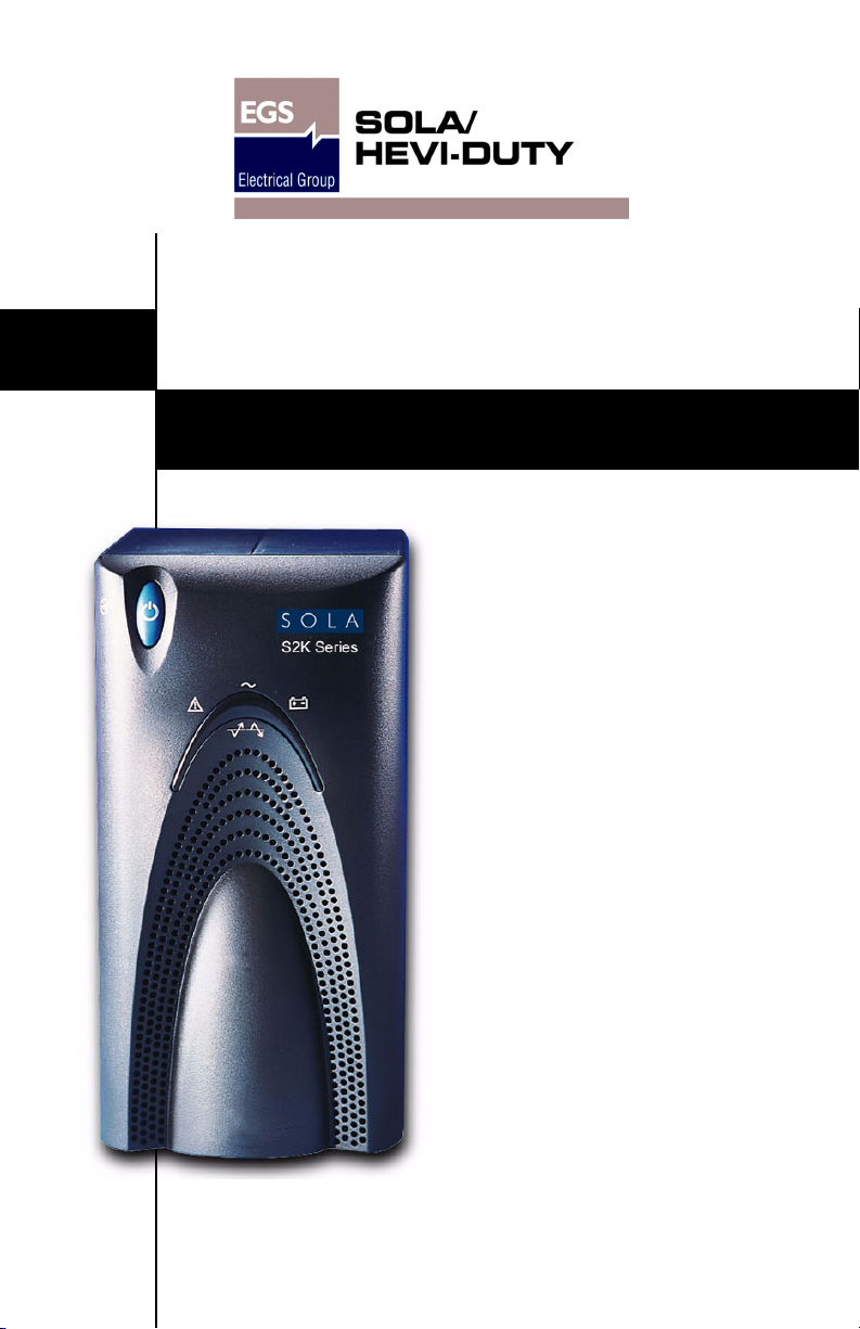
S2K UPS USER MANUAL
Line-Interactive
350-1000 VA
230V


i
TABLE OF CONTENTS
IMPORTANT SAFETY INSTRUCTIONS . . . . . . . . . . . . . . . . . . . . . 1
INTRODUCTION & SYSTEM DESCRIPTION . . . . . . . . . . . . . . . . . 5
Front View of UPS . . . . . . . . . . . . . . . . . . . . . . . . . . . . . . . . . . . . 6
Rear View of UPS. . . . . . . . . . . . . . . . . . . . . . . . . . . . . . . . . . . . . 7
MAJOR COMPONENTS. . . . . . . . . . . . . . . . . . . . . . . . . . . . . . . 8
Transient Voltage Surge Suppression (TVSS) & EMI/RFI
Filters . . . . . . . . . . . . . . . . . . . . . . . . . . . . . . . . . . . . . . . . . . . . . . 8
Automatic Voltage Regulator . . . . . . . . . . . . . . . . . . . . . . . . . . . 8
Bi-Directional Converter . . . . . . . . . . . . . . . . . . . . . . . . . . . . . . . 8
Battery . . . . . . . . . . . . . . . . . . . . . . . . . . . . . . . . . . . . . . . . . . . . . 8
WHAT’SINCLUDED . . . . . . . . . . . . . . . . . . . . . . . . . . . . . . . . . 9
INSTALLATION. . . . . . . . . . . . . . . . . . . . . . . . . . . . . . . . . . . . 10
CONTROLS AND INDICATORS. . . . . . . . . . . . . . . . . . . . . . . . . 12
ON/OFF/Alarm Silence Button . . . . . . . . . . . . . . . . . . . . . . . . 12
Status Indicators: Mains, Battery, Fault . . . . . . . . . . . . . . . . . 13
Mains Indicator (Green/Amber) . . . . . . . . . . . . . . . . . . . . . . . . . . 13
Battery Indicator (Green/Amber) . . . . . . . . . . . . . . . . . . . . . . . . . 13
Fault Indicator (Red/Green) . . . . . . . . . . . . . . . . . . . . . . . . . . . . . 13
Location and Status of Indicators . . . . . . . . . . . . . . . . . . . . . . . . . 13
Transfer Voltage Selectors (DIP Switches) . . . . . . . . . . . . . . . 14
MODES OF OPERATION . . . . . . . . . . . . . . . . . . . . . . . . . . . . . 15
Normal Mode . . . . . . . . . . . . . . . . . . . . . . . . . . . . . . . . . . . . . . . 15
Buck/Boost Mode . . . . . . . . . . . . . . . . . . . . . . . . . . . . . . . . . . . . 15
Battery Mode . . . . . . . . . . . . . . . . . . . . . . . . . . . . . . . . . . . . . . . 16
COMMUNICATIONS . . . . . . . . . . . . . . . . . . . . . . . . . . . . . . . . 17
DB-9 Connector . . . . . . . . . . . . . . . . . . . . . . . . . . . . . . . . . . . . . 17
Remote Shutdown Via the DB-9 Connector . . . . . . . . . . . . . . . 18
Shutdown Via Pins 5 & 6 . . . . . . . . . . . . . . . . . . . . . . . . . . . . . . . . 18
Shutdown Via Pins 4 & 5 . . . . . . . . . . . . . . . . . . . . . . . . . . . . . . . . 18
USB Interface Port. . . . . . . . . . . . . . . . . . . . . . . . . . . . . . . . . . . 18
Data Line Protection Connectors . . . . . . . . . . . . . . . . . . . . . . . 18

ii
MAINTENANCE . . . . . . . . . . . . . . . . . . . . . . . . . . . . . . . . . . . 19
Cleaning the UPS. . . . . . . . . . . . . . . . . . . . . . . . . . . . . . . . . . . . 19
Maintaining Batteries . . . . . . . . . . . . . . . . . . . . . . . . . . . . . . . . 19
Battery Replacement . . . . . . . . . . . . . . . . . . . . . . . . . . . . . . . . . 19
Battery Replacement Procedure . . . . . . . . . . . . . . . . . . . . . . . . . . 20
TROUBLESHOOTING . . . . . . . . . . . . . . . . . . . . . . . . . . . . . . . 21
Guide to Status Indicators. . . . . . . . . . . . . . . . . . . . . . . . . . . . . 21
Troubleshooting Chart. . . . . . . . . . . . . . . . . . . . . . . . . . . . . . . . 22
SPECIFICATIONS . . . . . . . . . . . . . . . . . . . . . . . . . . . . . . . . . 23
Battery Run Times. . . . . . . . . . . . . . . . . . . . . . . . . . . . . . . . . . . 24
Product Warranty Registration. . . . . . . . . . . . . . . . . . . . . . . . . 25

1
IMPORTANT SAFETY INSTRUCTIONS
SAVE THESE INSTRUCTIONS
This manual contains important safety instructions that should be fol-
lowed during the installation and maintenance of the Uninterruptible
Power System (UPS) and its batteries. Please read this manual thor-
oughly before attempting to install or operate this UPS.
Read all safety, installation, and operating instructions before operat-
ing the UPS. Adhere to all warnings on the unit and in this manual.
Follow all operating and user instructions.
This equipment is designed for Commercial, Industrial or Residential
use. Sola/Hevi-Duty neither recommends nor knowingly sells this
product for use in life support applications or with other designated
critical devices.
This equipment can be installed and operated by individuals without
previous training.
!WARNING
SAFETY PRECAUTIONS
• There are no user-serviceable parts inside this UPS except
the internal battery pack. Refer all UPS service to quali-
fied service personnel. Do not attempt to service this prod-
uct yourself.
• Output receptacles on the UPS are electrically live if the
UPS is switched on, even if the UPS is not plugged into a
Mains supply. The ON/OFF button on the UPS does not
electrically isolate the internal parts. Some components
are live even when Mains power is disconnected. To isolate
the UPS, switch off the UPS first, then unplug it from the
Mains.
• Opening or removing the cover may expose you to lethal
voltages within this unit even when it is apparently not
operating and the input wiring is disconnected from the
electrical source.
• Observe all CAUTION and WARNING statements in this
manual and on the unit. Failure to do so may result in
serious injury or death.
• Never work alone.

2
!WARNING
ELECTRICAL PRECAUTIONS
• This UPS should not be supplied from electrical power sys-
tems of the “IT” (Impedance á Terre) type (IEC 364 - Elec-
trical Installation of Buildings).
• The UPS must be earthed/grounded at all times during
operation. Connect only to a mains supply socket outlet
with an earth/ground connection.
!CAUTION
Although your UPS has been designed and manufactured to
assure personal safety, improper use may result in electrical
shock or fire. To ensure safety, please observe the following
rules:
• Turn off and unplug your UPS before cleaning. Do not use
liquid or aerosol cleaners. A dry cloth is recommended to
remove dust from the surface of your UPS.
• Do not install or operate your UPS in or near water.
• Do not place your UPS on an unstable cart, stand or table.
• Do not place your UPS in direct sunlight or near heat
emitting sources.
• Never block or insert any objects into the ventilation holes
or other openings of the UPS. Keep all vents free of dust
accumulation that could restrict airflow.
• Do not place the UPS power cord in any area where it may
be damaged by heavy objects.
• Placing magnetic storage on the top of the UPS may result
in data corruption.

3
!CAUTION
BATTERY HANDLING PRECAUTIONS
Servicing of batteries should be performed or supervised by
personnel knowledgeable of batteries and required
precautions. Keep unauthorized personnel away from the
batteries.
A battery can present a risk of electrical shock and high
short-circuit current. The following precautions should be
observed when working on batteries:
• Remove watches, rings, and other metal objects.
• Use tools with insulated handles.
• Do not dispose battery or batteries in a fire. The battery
may explode.
• Do not open or mutilate the battery or batteries. Released
electrolyte is harmful to skin and eyes. It may be toxic.
• When replacing the battery, use same number and type of
battery as the suitable recommended type of battery listed
in specification table in back of this manual.
• Handle, transport and recycle batteries in accordance with
local regulations.
!WARNING
If your UPS demonstrates any of the following conditions,
turn off and unplug your UPS from the outlet and contact
your local distributor, Sola/Hevi-Duty representative, or
Sola/Hevi-Duty Technical Services.
• The power cord is damaged.
• Liquid has been spilled on the UPS.
• The circuit breaker or fuse opens frequently.
• The UPS does not operate in accordance with the user
manual.

4
Electromagnetic Compatibility—The Sola S2K series complies
with the requirements of the EMC Directive 89/336/EEC and the pub-
lished technical standards. Continued compliance requires installa-
tion in accordance with these instructions and use of Sola/Hevi-Duty
approved accessories only.
Environmental—Operate the UPS in an indoor environment only in
an ambient temperature range of 0°C to 40°C (32°F to 104°F). Install
in a clean environment, free from conductive contaminates, moisture,
flammable liquids, gases, or corrosive substances.
Provided are a MultiLink cable and a USB cable for connection to a
computer. Do not use the MultiLink cable for other applications. Store
in a safe place if not required at this time.
When using the communication features on this UPS, ensure the
cabling connected to the DB-9 or UPS communications ports are kept
separated from the power leads to the UPS input and output.

5
INTRODUCTION & SYSTEM DESCRIPTION
Congratulations on your choice of the Sola S2K series Uninterruptible
Power System (UPS). It provides filtered AC power to sensitive elec-
tronic equipment and other critical loads.
The S2K unit is a line-interactive UPS designed for an office environ-
ment. It provides perfect power protection for PCs, point-of-sale sys-
tems, network and similar electronic equipment. It offers a
configurable input voltage window allowing you to precisely match
your equipment’s input power. Three communications options are
available: serial connection, contact closure and USB. The S2K unit is
available in four (4) sizes: 350, 500, 650 and 1000VA at 120 VAC and
230 VAC.
Sola S2K models are available for 120 VAC and 230 VAC supply volt-
ages and loads. Please verify that this model matches your AC Mains
and load voltage requirements.


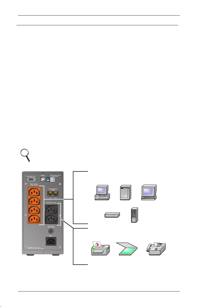
7
Rear View of UPS
DB-9
port***
Input circuit
protector
USB
port***
DIP
switches**
Orange output
receptacles*
Battery backup +
surge protection
Black output
receptacles (2)*
Surge protection
only
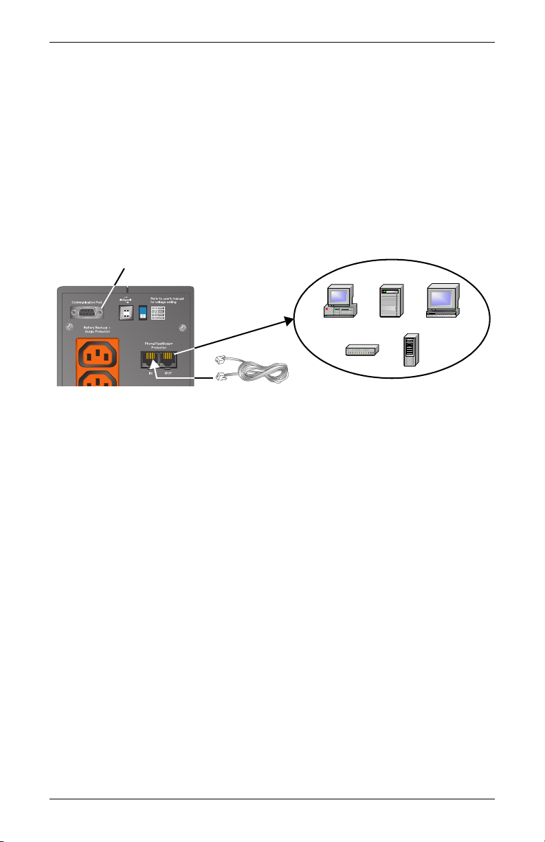
Data Line Protection
Connectors (2)***
Phone/Fax/DSL/Internet/
Modem devices
Battery cover plate
(on rear of 350 &
500VA models)
350&500VA
Models
Input circuit
protector
Orange output
receptacles*
Battery backup +
surge protection Black output
receptacles (2)*
Surge protection
only
Data Line Protection
Connectors (2)***
Phone/Fax/DSL/Internet/
Modem devices
For details, see:
* Installation section
** Controls and Indicators section
*** Communications section
Battery cover plate
(bottom of unit for
650 & 1000VA models)
650 &1000 VA
Models
NOTE: Bottom
two receptacles
on 1000VA
models only
AC
input
AC
input
DB-9
port***
USB
port***
DIP
switches**

8
MAJOR COMPONENTS
Transient Voltage Surge Suppression (TVSS) & EMI/RFI
Filters
These UPS components provide surge protection and filter electro-
magnetic interference (EMI) and radio frequency interference (RFI).
They minimize surges or interference present in the mains line and
keep the sensitive equipment protected.
Automatic Voltage Regulator
The Automatic Voltage Regulator (AVR) protects connected equip-
ment from power spikes and other abnormalities by raising an under-
voltage (boost) and lowering an overvoltage (buck) as needed. This
keeps the UPS output voltage within the connected equipment’s toler-
ance and accommodates wide mains voltage fluctuations without uti-
lizing the batteries.
Bi-Directional Converter
In normal operation, the Bi-Directional Converter changes mains AC
power into regulated DC power to “float charge” the battery system.
This converter is continuously charging the battery whenever the UPS
is plugged into a power outlet and mains power is within acceptable
limits—even if the UPS is turned OFF.
When mains power fails, the Bi-Directional Converter draws energy
from the battery and inverts it into a regulated stepped sinewave sup-
plying power for equipment connected to the orange receptacles.
Battery
The S2K unit utilizes valve-regulated, nonspillable, lead acid batter-
ies. To optimize battery life, operate the UPS in an ambient tempera-
ture of 20°-25°C (68°-77°F).
TVSS &
EMI/RFI
Filters
Automatic
Voltage
Regulator
Battery Bi-Directional
Converter
Input Output
G
N
L
G
N
L

9
WHAT’SINCLUDED
The S2K unit is shipped with the following items:
• Sola S2K user manual
• MultiLink™ software CD
• MultiLink serial cable, 3.0m (10 ft.)
• USB cable, 1.8m (6 ft.)
• RJ-11 cord, 2.1m (7 ft.)
• Two (2) 10A output power cords, 2.0m (6.6 ft.)
MultiLink
serial cable
3.0m (10 ft.)
Sola S2K
Unit
MultiLink
software CD
USB cable
1.8m (6 ft.)
RJ-11 cord
2.1m (7 ft.)
Two (2) 10A output
power cords, 2.0m
(6.6 ft.)
10
INSTALLATION
This UPS is designed for data processing equipment. Maximum load
must not exceed that shown on the UPS rating label. Do not connect
equipment that could overload the UPS or draw half-wave current
from the UPS, for example: electric drills, vacuum cleaners, laser
printers or hair dryers. Your total load earth leakage current must not
exceed 3.5 mA. Most data processing equipment meets this require-
ment if you use no more than two pieces of equipment. If uncertain
about your load, consult your local distributor, Sola/Hevi-Duty repre-
sentative, or Sola/Hevi-Duty Technical Services.
1. Visually inspect the UPS for freight damage. Report damage to the
carrier and your local distributor, Sola/Hevi-Duty representative, or
Sola/Hevi-Duty Technical Services.
2. Decide where to place the S2K unit. Find a location that is near an
easily accessible mains outlet. Install the UPS indoors in a con-
trolled environment, where it cannot be accidentally turned off.
Place it in an area of unrestricted airflow around the unit, away
from water, flammable liquids, gases, corrosives, and conductive
contaminants. Maintain a minimum clearance of 100mm (4 inches)
on each side of the UPS. Maintain an ambient temperature range of
0°C to 40°C (32°F to 104°F).
3. The Sola S2K 230 VAC models are not supplied with an input power
lead for connection to the mains supply. Additional input/output
leads can be obtained from your dealer. The input power cord must
have a minimal cross-sectional area of 1mm2.
NOTE
UPS operation in temperatures above 25°C (77°F) reduces
battery life.
Plug this type of equipment into black
receptacles ONLY
Plug computers, monitors & network hubs
into orange receptacles
Inkjet
printer
Scanner Fax
machine
11
4. Shut down the load equipment and turn off the mains supply.
Unplug the load equipment’s power input cable from the mains sup-
ply socket and plug it into the UPS input socket. Plug the power
input cable into the mains supply socket.
Connect the supplied IEC-320-C14 output power cable between the
load equipment input socket and one of the UPS AC output sockets.
Connect all load equipment to the UPS in this manner.
5. Plug any computers and monitors into the orange battery backed up
receptacles.
Other office machines that do not exceed the capacity of the UPS—ink-
jet printers, scanners and fax machines—may be plugged into either of
the two (2) black receptacles, which provide surge protection only.
6. Connect Phone/Fax/DSL/Internet/Modem devices to data line connectors.
7. Press and release the ON/OFF/Alarm Silence button to turn on the
UPS. The UPS will beep and the Mains Indicator will illuminate (green).
8. Turn on connected equipment.
9. Communication options (see Communications section for details):
Option 1—Serial Communications
Serial communications provides parametric data, for example,
input voltage and battery voltage.
a. Connect MultiLink serial cable included with the UPS to commu-
nications port.
b. Install the MultiLink software—the software and installation
instructions, as well as the user manual, are on the CD included
in the Sola S2K package.
Option 2—Contact Closure Communications
Contact Closure communications provides on-battery and low-bat-
tery signals for orderly shutdown.
a. Refer to the MultiLink user manual for instructions on making
your own contact closure cable.
b. Install the MultiLink software—the software and installation
instructions, as well as the user manual, are on the CD included
in the Sola S2K package.
Option 3—USB Communications
a. Connect USB cable provided with the UPS to the USB ports on the
S2K and your computer. The S2K will work automatically with your
built-in power management software on Windows XP and 2000 and
Mac OS 10.2 or later (see USB Interface Port section for details).
Serial port for MultiLink cable connection

12
CONTROLS AND INDICATORS
ON/OFF/Alarm Silence Button
This button controls output power to the
connected load and has three functions:
•ON
•OFF
• Alarm Silence
ON When the UPS is off, pressing and releasing the main ON/
OFF button will start the UPS, and an audible alarm sounds
briefly. The UPS is capable of starting on battery (battery
start).
OFF When the UPS is on (in either Normal or Battery mode),
pressing the main ON/OFF button for more than
two (2) seconds will shut down the UPS. An audible alarm
sounds briefly.
Alarm
Silence
When a UPS alarm is active, pressing and releasing the
main ON/OFF button will silence the active audible alarm,
whether mains power is present or not. Once the alarm
silence function has been activated, all active audible
alarms—except for low battery, overload, or over-tempera-
ture conditions—will remain silenced until a new alarm con-
dition is detected.
NOTE
Do not hold ON/OFF button down for more than 2 seconds
or the UPS will shut down.
ON/OFF/Alarm Silence

13
Status Indicators: Mains, Battery, Fault
There are three (3) status indicators on the front of the UPS (Mains,
Battery and Fault), as shown in the diagram below. Each indicator
illuminates to specify the status of the UPS (see Troubleshooting
section for details).
Mains Indicator (Green/Amber)
The Mains Indicator illuminates when the UPS is operating and sup-
plying power to connected loads: green indicates Normal mode, amber
denotes Buck/Boost mode.
Battery Indicator (Green/Amber)
The Battery Indicator illuminates to indicate the UPS is operating on
battery (green) or to signify a battery warning (amber).
Fault Indicator (Red/Green)
The Fault Indicator illuminates when the UPS detects a problem: red
for an internal UPS fault, green for overload and over-temperature
conditions.
Location and Status of Indicators
Fault Indicator
Green: Overload/Over temperature
Red: UPS fault
Mains Indicator
Green: Normal operation
Amber: Buck/Boost mode
Battery Indicator
Green: On battery
Amber: Battery warning
NOTE
See Troubleshooting section for details.
14
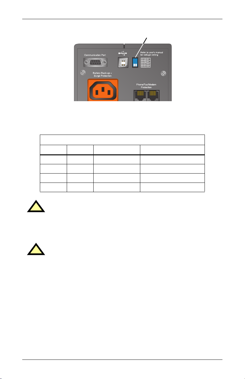
Transfer Voltage Selectors (DIP Switches)
The two-position DIP switch control on the rear panel, shown above,
allows the operator to select the mains transfer voltage at which the
UPS will switch to battery power. DIP switch positions for each volt-
age setting are as follows:
DIP switch settings
Left Right Nominal Mains Input Range Setting
↑Up ↑Up 230VAC 163 - 282VAC (default)
↑Up ↓Down 220VAC 155 - 270VAC
↓Down ↑Up 240VAC 171 - 291VAC
↓Down ↓Down 230VAC 163 - 282VAC
!CAUTION
Never change the voltage settings while the UPS is ON and
powering connected loads. Change DIP switches only when
the UPS is OFF.
!CAUTION
To ensure protection of the connected equipment, the DIP
switch settings should match the nominal mains input
voltage. DIP switch settings not matching the nominal
mains could potentially damage connected equipment.
Rear of UPS DIP Switches

15
MODES OF OPERATION
Normal Mode
During Normal mode operation, the S2K unit supplies conditioned,
computer-grade power to the connected equipment: mains power
passes through the TVSS circuitry and the EMI/RFI filters and then
through the Bi-Directional Converter to connected equipment.
When the UPS is in Normal mode, the Mains Indicator illuminates
green.
The S2K unit continuously monitors the batteries to maintain them in
a fully charged state. The battery charger operates whenever AC
power is present, even if the UPS is switched off. By default, the UPS
is set to perform an automatic battery test after it has been operating
continuously for two (2) weeks. The interval at which the UPS will
perform a battery test can be configured via MultiLink.
Buck/Boost Mode
The Automatic Voltage Regulator (AVR) circuitry compensates for
fluctuations in mains power, such as voltage surges and sags. When
the S2K unit detects an abnormality, it raises the undervoltage
(boost) or lowers the overvoltage (buck) as needed. The AVR operates
automatically and maintains the output voltage to the connected criti-
cal equipment, without utilizing the batteries.
When the UPS is in Buck/Boost mode, the Mains Indicator illumi-
nates amber.
Mains Indicator (Green)
Mains Indicator (Amber)

16
Battery Mode
The UPS switches to Battery mode in the event of an extreme voltage/
frequency condition or complete mains failure. The battery system
supplies power through the Bi-Directional Converter to generate
power for connected equipment.
When the UPS is in Battery mode, the Battery Indicator illuminates
green and an alarm sounds every 10 seconds.
When a low battery condition occurs, the Battery Indicator changes to
flashing amber and the alarm sounds every half-second. Low battery
warning is defaulted to two (2) minutes but can be configured via Mul-
tiLink. For more information, refer to Troubleshooting section.
!CAUTION
Turning off the UPS while in either Normal mode or Battery
mode will result in the loss of output power.
NOTE
Once mains power is restored, the UPS resumes normal
operation. At this time, the battery charger begins recharging
the battery. The UPS is capable of OFF-State charging, i.e.,
with mains power, the UPS will charge the batteries as long
as it is plugged in.
Battery Indicator (Green)
Battery Indicator (flashing Amber)
Table of contents
Other Sola Hevi Duty UPS manuals

Sola Hevi Duty
Sola Hevi Duty S4K6U10000 User manual

Sola Hevi Duty
Sola Hevi Duty S3K2U User manual

Sola Hevi Duty
Sola Hevi Duty S4K4U6000 User manual

Sola Hevi Duty
Sola Hevi Duty S4K5U6000-5 User manual

Sola Hevi Duty
Sola Hevi Duty S1K320 User manual

Sola Hevi Duty
Sola Hevi Duty S4K2U Series User manual

Sola Hevi Duty
Sola Hevi Duty S5K User manual


