Sola-Tecs F Series User manual

SOLA-TECS F
Assembly instructions
BJ 2019 …
SN 2917 …
F2000 | F3200 | F4000
MA 0302506 R00 2019-07
Overview
2
MA 0302506 R00 2019-07
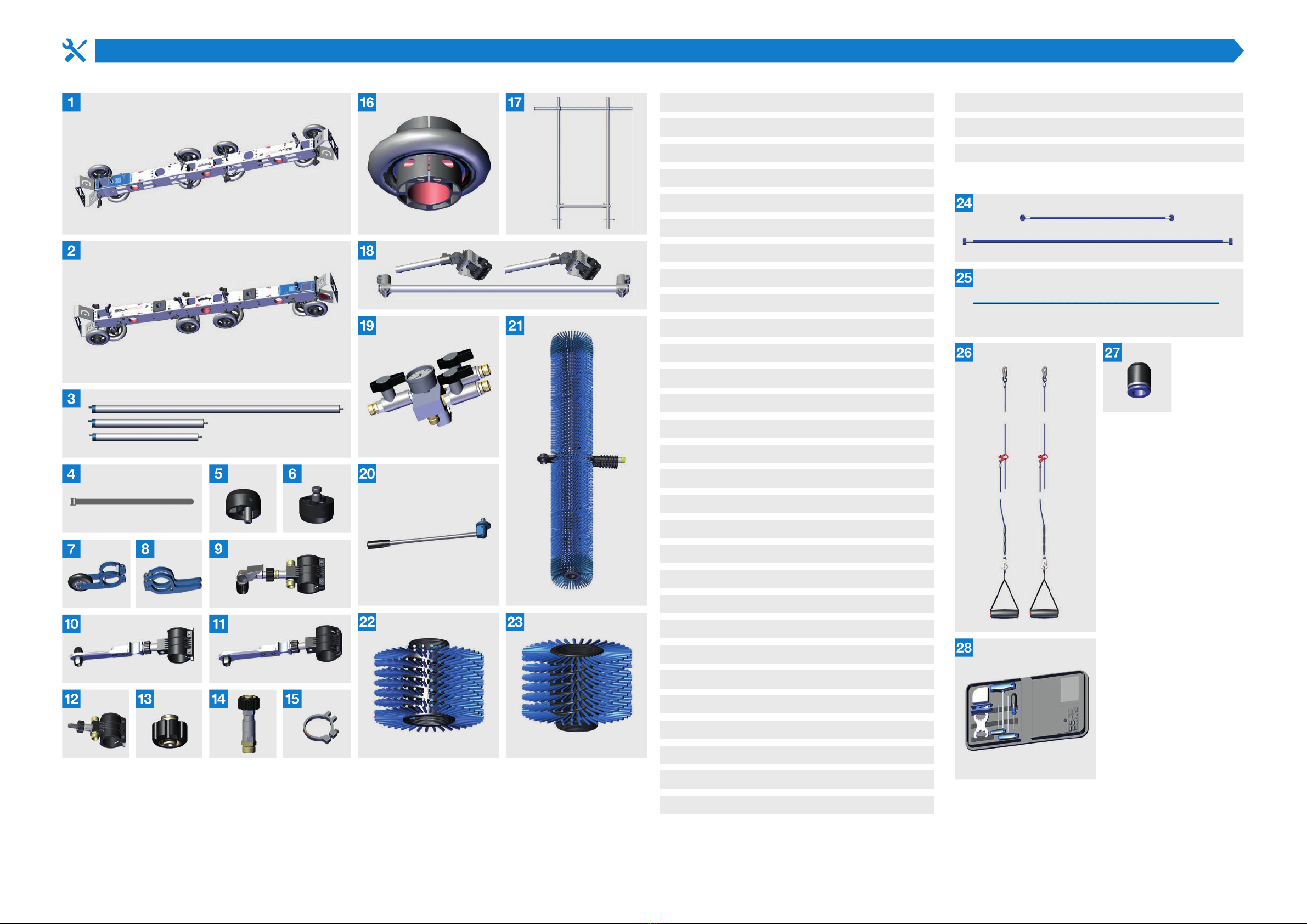
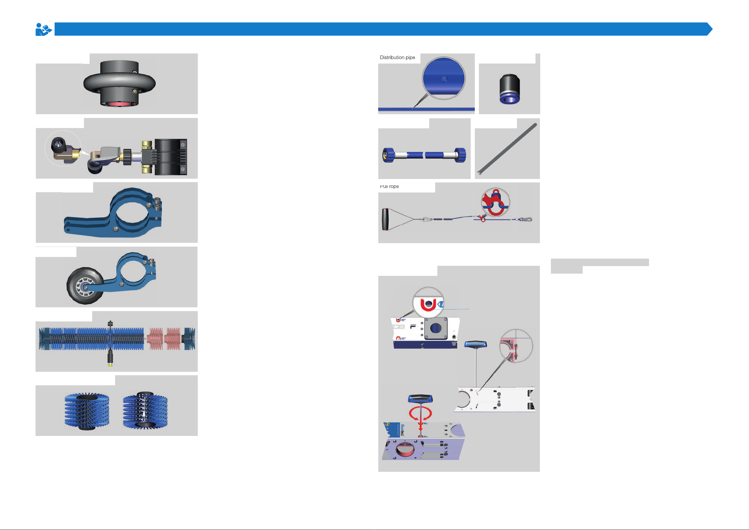
Component
11300 top carriage
21300 bottom carriage
3L1600 connecting tube element
L700 connecting tube element
L800 connecting tube element
4Velcro cable ties
5Active end cap
6Passive end cap
7Roll holder
8Brush stop
9SOLA-TECS F spray nozzle
0Guide bearings
Counterholder
Clamping element with connection
M22 x 1.5 plug
M22 x 1.5 swivel joint
Stop clamp
Relief roller
Top support frame
Bottom support frame
Water distributor
Passive lever
SOLA-TECS C 1000 - Hammer head
Brush roller left 100 mm
Brush roller right 100 mm
NW6 HD hose 2000 mm
NW8 HD hose 1000 mm
Distribution pipe 1500 mm
SOLA-TECS F 3.5 meter pull rope
SOLA-TECS F 6.5 meters pull rope
IQS standard sealing cap
Tool bag
3
MA 0302506 R00 2019-07
Introduction
It is IMPORTANT that you read these
operating instructions carefully READ CAREFULLY BEFORE USE
and KEEP FOR FUTURE REFERENCE.
Technical data
SOLA-TECS F BJ 2019 …
Seriennummer SN 2917 …
Space requirement Required floor space 5 m x 1.5 m
Required functional area min. 1 m x 1.5 m
Distance from floor to panel 150 mm
Work and maintenance stations Space required for assembly 8 m x 3 m
Working area 800 mm - 4000 mm
Movement space at workplaces min 5 m
Safety area in operating direction min. 1 m
Safety area around the operator 1 m
Bridgeable distance from panel to panel 400 mm
Weight and operating materials Weight min. 43 kg
Drive medium - water, ultrapure water
Cleaning substance - water, ultrapure water
Drive types and High water pressure
performance data High pressure max. 140 bar
Operating pressure 100 bar
Water consumption max. 3 L/min per
drive unit and 1.5 L/min per spray nozzle
Operating temperature 40 °C
Brush revolutions at diameter
160 mm – 700 rpm
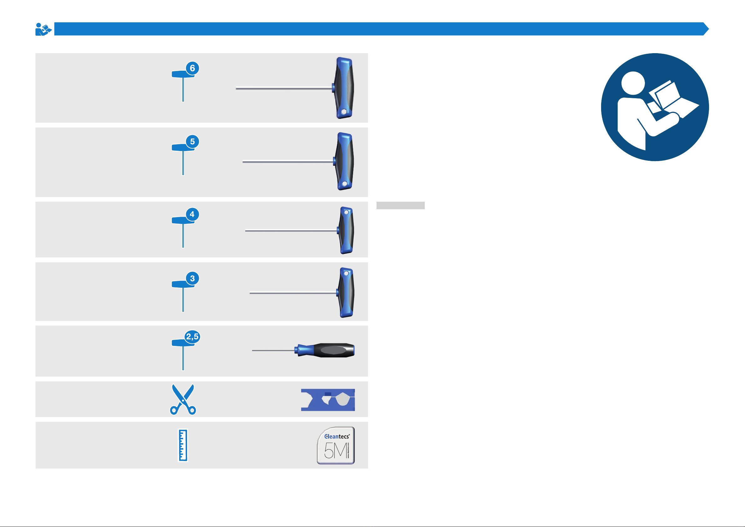
Exagon socket - Size 5
Measuring tape - 5 Meter
Hose cutter
Exagon socket - Size 4
Exagon socket - Size 3
Exagon socket - Size 2,5
Exagon socket - Size 6
4
MA 0302506 R00 2019-07
Introduction
Safety instructions
Pay attention to the warning and safety instructions in
these operating instructions! This will protect you from
injuries.
AIn the case of bad weather, ensure that
appropriate protective clothing is worn.
This protects you from illness due to
hypothermia.
WARNING
Hazard due to bad weather
AAvoid using the machine during
thunderstorms.
This protects you from injury caused by
lightning and from hypothermia.
WARNING
Hazard due to thunderstorms
AWear gloves during disassembly.
This protects your skin from abrasions and
pinching.
WARNING
Risk of injury during disassembly
AWear gloves during assembly.
This protects your skin from abrasions and
pinching.
WARNING
Risk of injury during assembly
AMake sure to lift the machine ergonomically.
This protects you from injuries caused by
straining your back.
WARNING
Risk of injury when lifting heavy parts
ACheck all high-pressure hoses and
connections for damage.
This protects you from injuries caused by
intense water jets.
WARNING
Risk of injury due to damage
ADo not allow the machine to freeze. This
can cause damage to the high-pressure
components.
This protects you from injuries caused by
intense water jets.
WARNING
Verletzungsgefahr durch Beschädigungen
AAlways tighten joints and check thoroughly.
This protects you from injuries caused by
uncontrolled ying parts.
WARNING
Risk of injury due to incorrect assembly or
installation
ACheck that all high-pressure connections
have been installed properly.
This protects you from injuries caused by
intense water jets.
WARNING
Risk of injury due to incorrect assembly or
installation
ACheck that the machine is positioned
correctly.
This protects you from injuries caused by the
machine falling down.
WARNING
Risk of injury due to falling machine
ACheck the area to be cleaned for parts that
can fall off.
This protects you from injuries caused by
falling parts.
WARNING
Risk of injury due to falling parts
ADo not operate the machine above the
specied maximum operating pressure.
This protects you from injuries caused by
uncontrolled ying parts.
WARNING
Risk of injury due to excessive operating
pressure
AStart and stop the machine only via the
stopcock.
This protects you from injuries caused by the
machine starting suddenly and accidentally.
WARNING
Risk of injury due to sudden start
ACheck if there is anything on your tread that
could encourage slipping.
This protects you from injuries caused by
falling.
WARNING
Risk of injury due to slippery tread
AAvoid working on the machine near the
rotating parts with long hair protected.
This protects you from injuries caused by your
hair getting caught in the machine.
WARNING
Risk of injury due to moving parts
AAvoid touching the machine near the
rotating parts.
This protects you from injuries caused by
pinching.
WARNING
Risk of injury due to moving parts
Intended use
The SOLA-TECS F system is intended for cleaning photo-
voltaic panels in the commercial sector. The photovoltaic
panels must be mounted on an elevation. The photovoltaic
panel must be at least 150 mm from the ground.
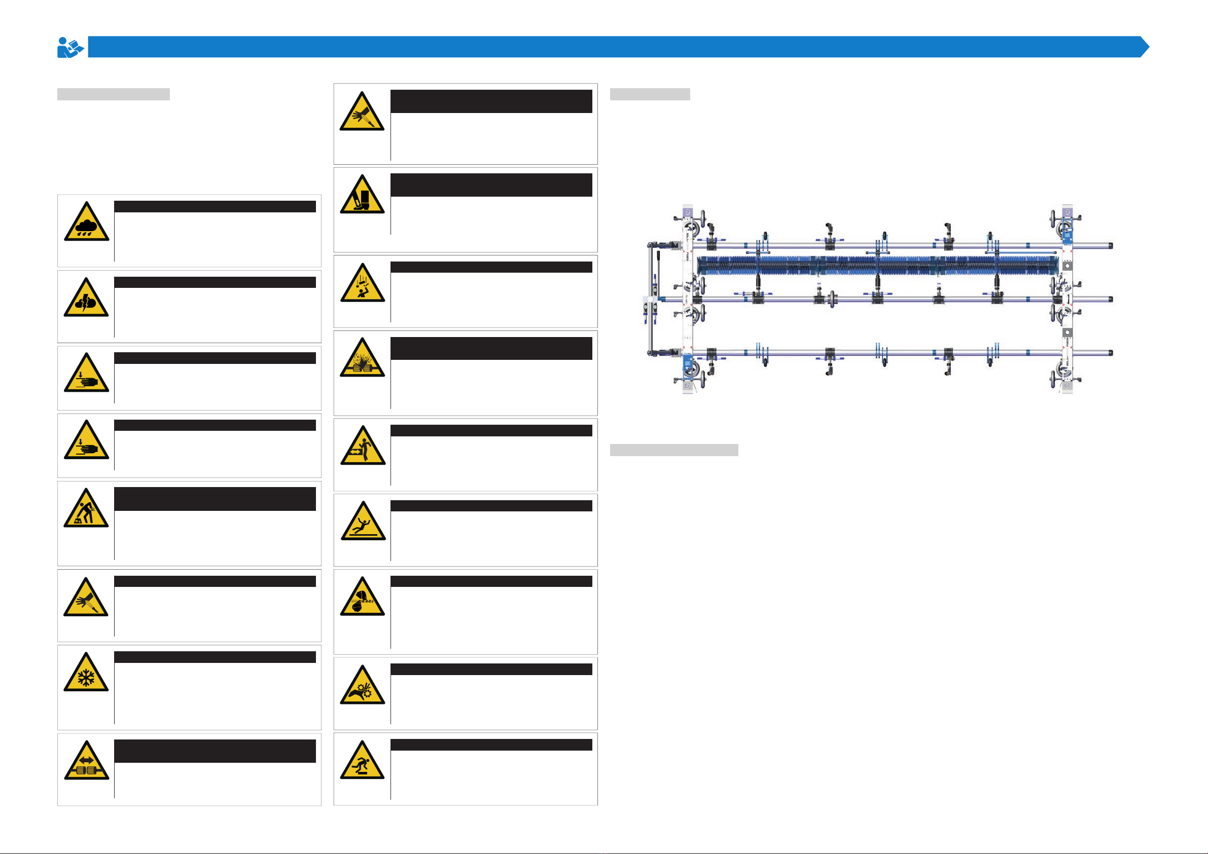
Structure and function
The SOLA-TECS F system consists of a carrier system on
two carriages. Brush rollers are mounted on these carriages,
which are driven by high-pressure water.
The carrier system consists of two opposite carriages con-
nected by three connecting tubes. Wheels are attached to
the carriages. The wheels have two functions: They enable
rolling over the photovoltaic panels and secure the carrier
system from slipping.
Brush rollers are mounted on the central connecting tube for
cleaning work and propulsion. The brush rollers work across
the entire width of the carrier system and are rotated by a
high-pressure water turbine. After the drive, the water used
is fed into the brush roller and spray nozzles. Here the water
is used to moisten, clean and rinse the photovoltaic surface.
The central connecting tube can swivel 180° using a lever
together with the mounted brush rollers to clean the photo-
voltaic panels in both directions up to the edge.
The system has additional spray nozzles for if the photo-
voltaic frames are particularly dirty. The spray nozzles and
the brush rollers can be switched on or off independently of
each other via a water distributor.
The SOLA-TECS F system is pulled in the working direction
by two pull ropes attached to the carriage. The length of the
pull ropes can be adjusted to ensure correct posture.
ACheck your work area for bumps and
obstacles.
This protects you from injuries caused by
falling.
WARNING
Risk of injury due to falling
5
MA 0302506 R00 2019-07
Introduction
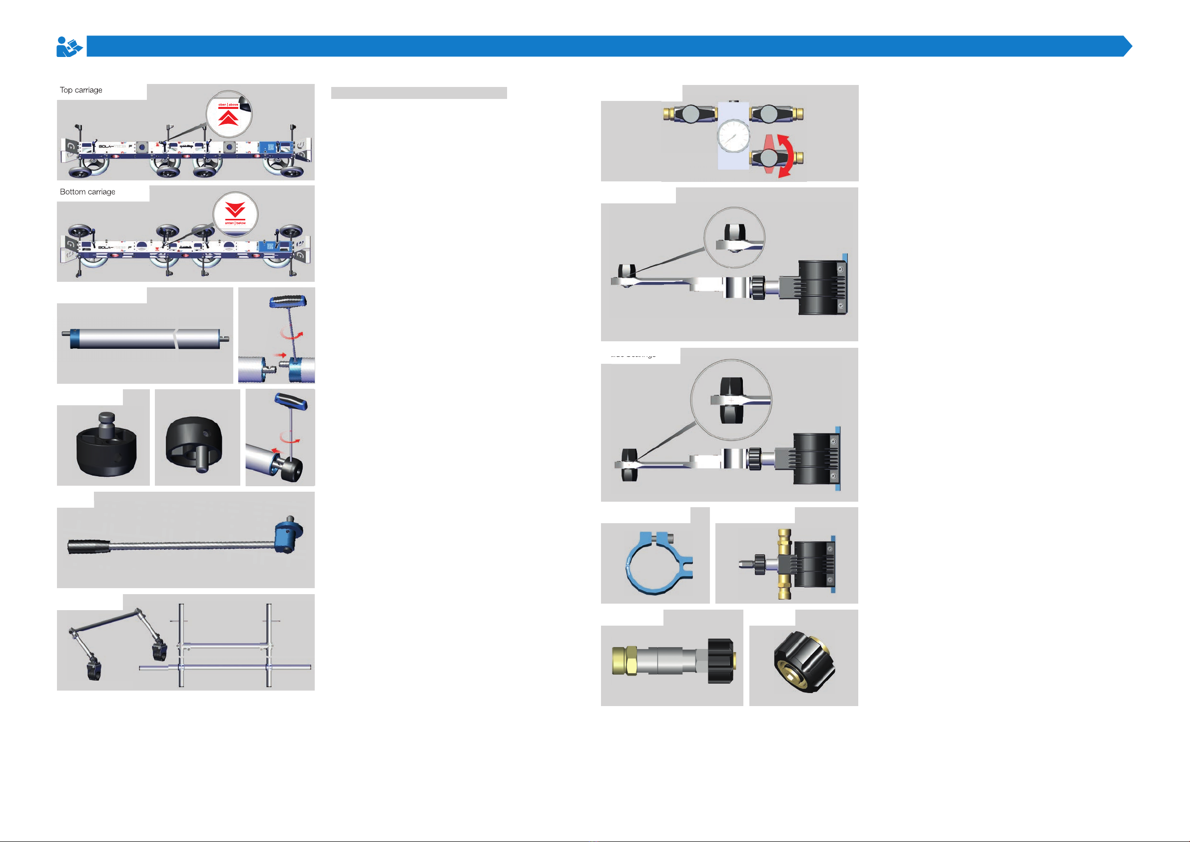
Components and their function
The top and bottom carriages are the drive units of the
carrier system. With them, the SOLA-TECS F system can
be rolled over the photovoltaic panels.
The settings for running behavior over the photovoltaic
panels can be adjusted on the carriage.
The connecting tubes of lengths 700 mm, 800 mm and
1600 mm are for connecting the carriages. The pipes are
connected via an active and passive coupling.
The active and passive end caps protect the tube ends
and joints on the carriage.
The passive lever is for the “swivel brush roller” func-
tion. It is mounted on the middle connecting tube (bottom
carriage).
The top and bottom support frames are the handles
for attaching the Sola-tecs F system to the photovoltaic
panels.
Top carriage
Bottom carriage
Connecting tube
End cap
Support frame
Lever
The water distributor is mounted on the lower carrying
handle. The water supply is switched on and off at the
water distributor.
The counter bearing guides the brush roller ends up and
down. It prevents the brush ends from swinging up.
The guide bearing connects the individual drive units to
form one unit and ensures a flexible connection.
The clamping element and its connection fasten the Sola-
Tecs C.
The stop clamp is the position stop for the counter be-
aring, guide bearing and clamping element.
The swivel joint prevents the high pressure hose from
twisting when the middle connecting tube is swiveled.
The plug closes the high-pressure area in the individual
supply lines.
Guide bearings
Stop clamp Clamping element
Water distributor
Counterholder
Swivel joint Plug
Guide bearings
Top carriage
Bottom carriage
6
MA 0302506 R00 2019-07
Introduction
Relief roller
Spray nozzle
Brush stop
From a structure of 3200 mm, the relief roller supports the
middle connecting tube when swiveling.
The spray nozzle cleans the hard-to-reach frame edges of
the photovoltaic panels.
The brush stop prevents the drive unit from sagging when
driving over gaps between the photovoltaic panels.
The roll holder facilitates crossing gaps between photo-
voltaic panels when the drive units rest on the brush stops
when crossing a gap.
Together with the mounted brush rollers, the Sola-Tecs C is
the cleaning/drive unit.
The 100 mm wide brush rollers are screwed to the brush
rollers of the Sola-Tecs C to extend the cleaning width.
Roll holder
Sola-Tecs C
Brush roller 100 mm
Distribution pipe Sealing cap
HD hose Velcro cable ties
Pull rope
The distribution pipe evenly sprays water onto the photo-
voltaic panel.
The sealing cap closes the distributor pipe.
The 2000 mm, 1500 mm and 1000 mm high-pressure ho-
ses supply water to the individual supply lines..
The cable ties fix the high-pressure hoses to the carrier
system.
The pull ropes are for pulling the Sola-Tecs F system over
the photovoltaic panels.
Control elements and their
function
Fixing the connecting tubes: The connecting tubes are
clamped to the carriage at the holes marked with a red [1]
and with a letter [A],[B],[C],[D],[E],[F].
Distribution pipe
Pull rope
Clamping
[1]

7
MA 0302506 R00 2019-07
Introduction
Adjusting the wheels: To adjust the wheels on the frame
of the photovoltaic panel, each wheel can be moved over
the axle.
Compensation for unevenness: The vertical wheels are
spring-mounted to compensate for unevenness. The spring
travel can be mechanically switched off with an adjusting
disc [1].
Wheels
Spring-mounted
Spring-mounted
[1]
Parking
Coupling which
Parking the Sola-Tecs F: When the mounted Sola-Tecs F
is not required, the whole unit can be placed on the sup-
port plates [1].
Connect the connecting tubes:
The connecting tubes are connected via a coupling which
has an active [1] and a passive [2] side. The coupling is lo-
cked via a grub screw [3] on the active coupling side.
Protecting the connecting tubes:
The ends of the connecting tubes are protected with end
caps [4]. There is one version each for the active and
passive coupling.
[1]
[1]
[2]
[4]
[3]

8
MA 0302506 R00 2019-07
Introduction
Adjustment and alignment:
A scale [1] is lasered on the connecting tubes. The scale
always starts on the active coupling side with zero and
is divided into two millimeter steps until the end of the
connecting tube. The scale allows for easier adjustment of
distances. The mark [2] helps to align the connecting tube
horizontally.
Water distribution controls: The distribution of pressuri-
zed water is regulated at the water distributor.
Cleaning brushes controls: The water distributor is sup-
plied with high pressure water at connection [1]. Lever [2]
is used to switch the brush roller on and off.
Scales and markers
Control of water distribution
[1]
[2]
[2]
[1]
Spray nozzle controls: The spray nozzles are controlled
via levers [1] and [2]. The water quantity can be controlled
by gradual opening of the nozzle.
Set the travel limit and clearance of Sola-Tecs C:
The travel limit and clearance are set with the stop clamp.
The stop clamp can be tightened and released with the
screw [1].
Adjust the spray nozzle: By opening the clamping lever
[1], the angle adjustment is released and can be adjusted.
Control of water distribution
Travel limit / clearance of Sola-Tecs C
Adjust the spray nozzle
[2]
[1]
[1]
[1]
[1]
9
MA 0302506 R00 2019-07
Introduction
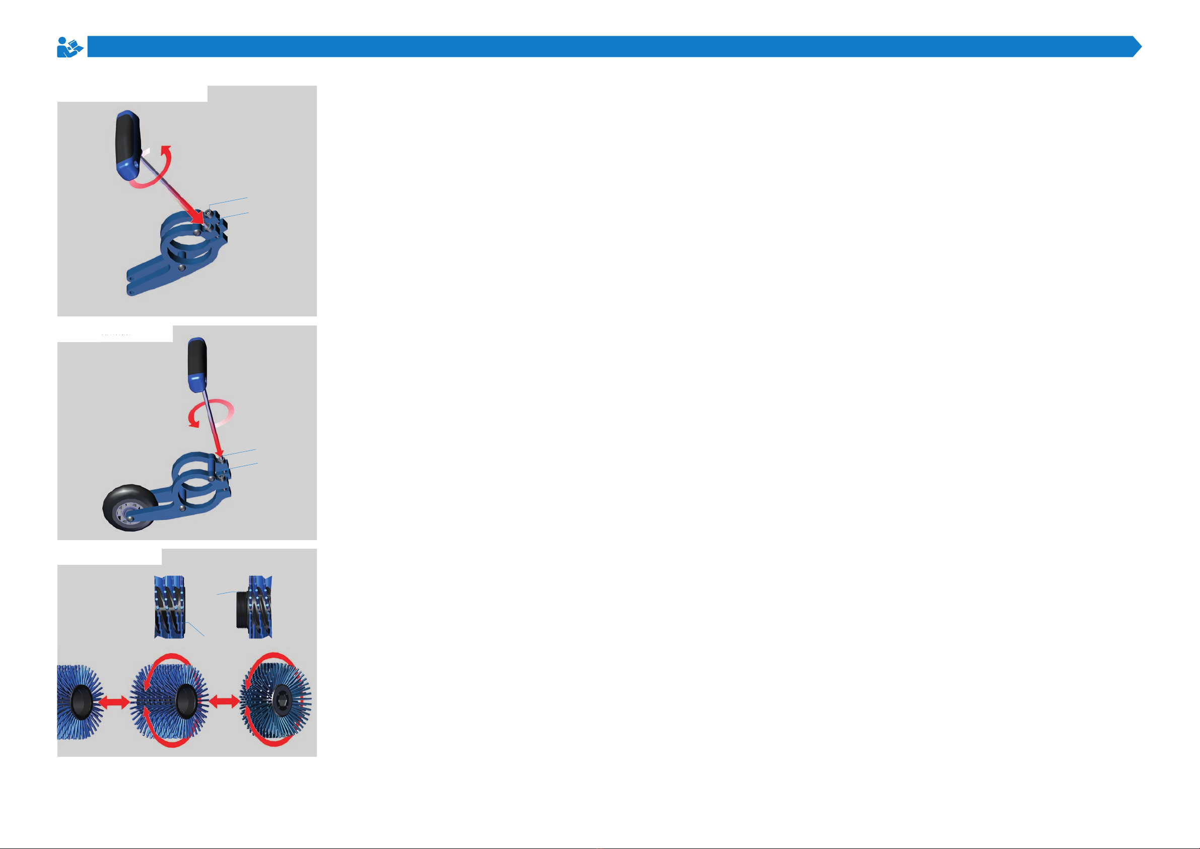
Adjust brush stop: The brush stop is released and clam-
ped with screws [1] and [2].
Adjust the roll holder: The roll holder is loosened and
clamped with screws [1] and [2].
Adjust the width of the brush roller: The Sola-Tecs C
brush rollers are divided into segments. The individual seg-
ments are connected by a thread [1][2]. The width of the
cleaner can be changed by inserting or removing individual
segments.
Adjust brush stop
Adjust the roll holder
The width of the brush roller
[2]
[2]
[2]
[1]
[1]
[1]
Adjust the roll holder
10
MA 0302506 R00 2019-07
Construction
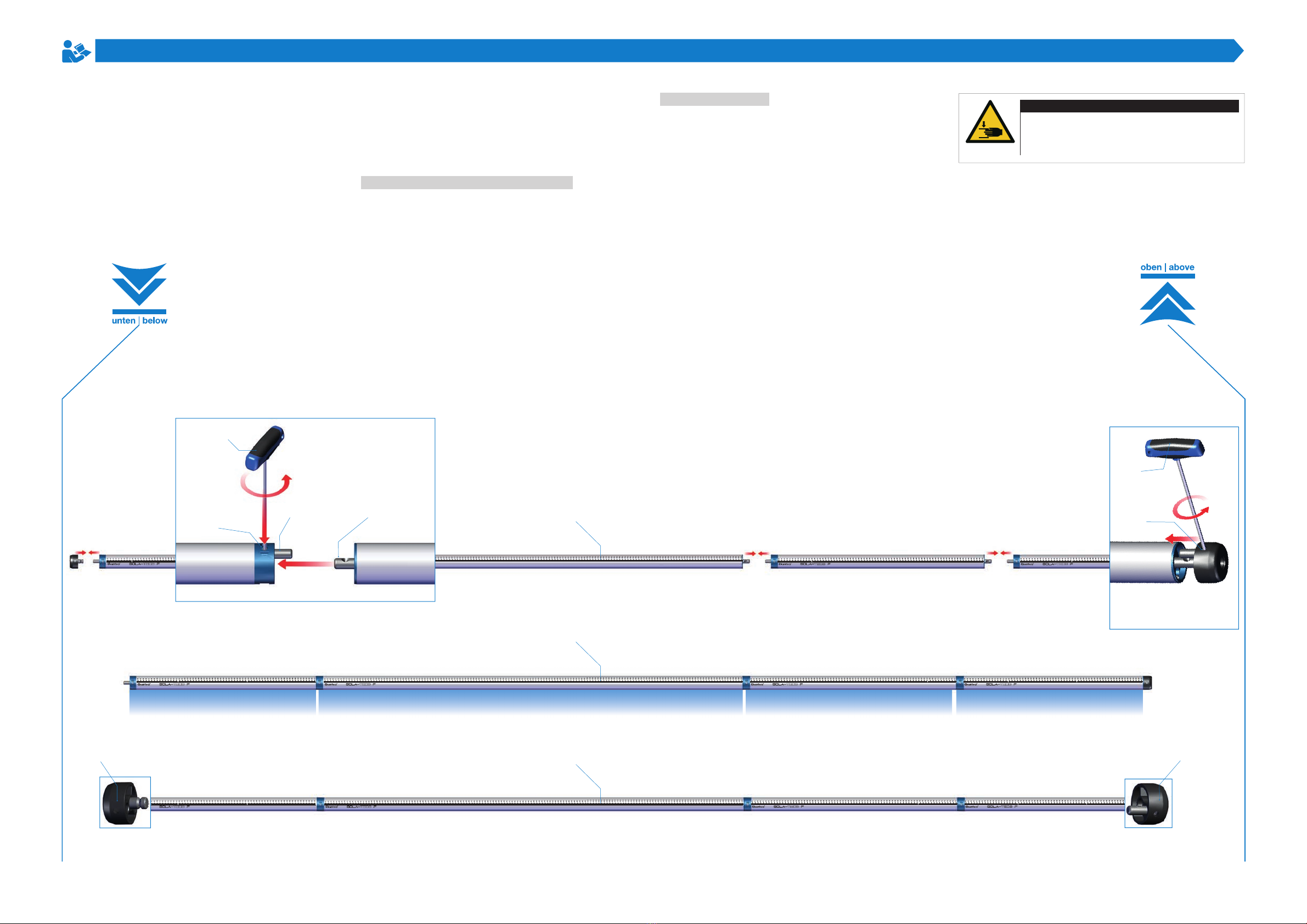
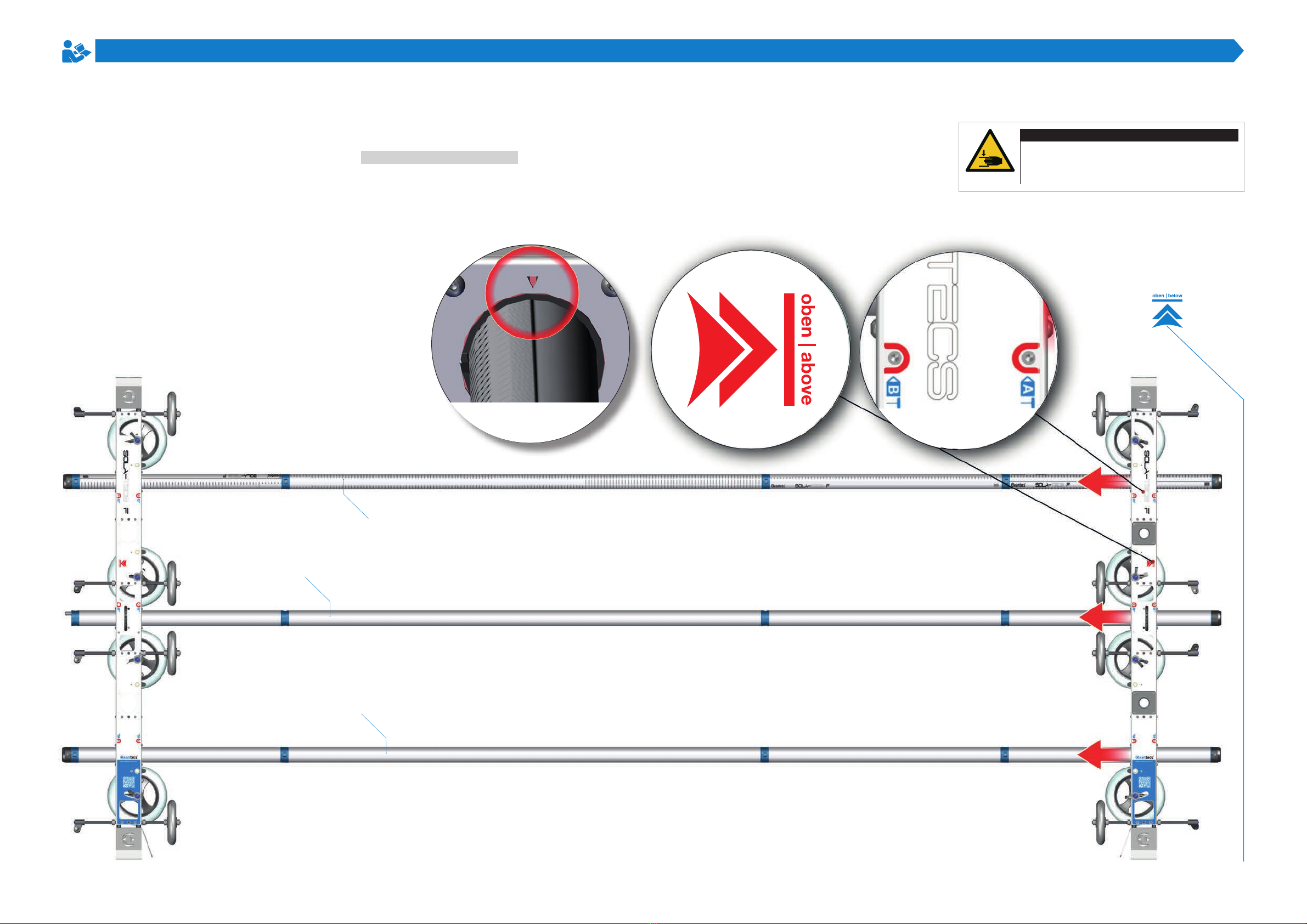
Assembly of the
connecting tubes
Lay out the connecting tube elements at the level mounting
location as shown. The active couplings must face [down].
The first and last connecting tube element should always
be an L700. The lengths of the connecting tube elements
between the L700 must be determined according to the re-
quired installation size. Make sure that all three connecting
tubes are divided equally. The scale must be continuous
from one connecting tube element to the next. Install the
end caps to protect the connecting tube couplings that are
not required. The end caps are mounted on [VR1] and [VR3]
at the beginning and end and on [VR2] only at the end.
Couple connecting tube elements:
Insert the passive [1] coupling into the active [2] coupling.
Using the hex key 4 [3], tighten the grub screw [4] on the
active coupling to 4NM.
Couple end caps:
The end caps are designed as active [5] and passive [6].
The passive end caps are mounted on the [bottom] and
the active end caps on the [top]. Using the hex key 4 [3],
tighten the grub screw [4] on the active coupling to 4NM.
[VR1]
[VR2]
[VR3]
0200748 0200748
0200748
0200748
0200748
0200747
0200747
0200747
[1]
[2]
[3]
[4]
0200746
0200746
0200746
[6]
[5]
[3]
[4]
AWear gloves during assembly.
This protects your skin from abrasions and
pinching.
WARNING
Risk of injury during assembly
L700 L700L800L1600
11
MA 0302506 R00 2019-07
Construction
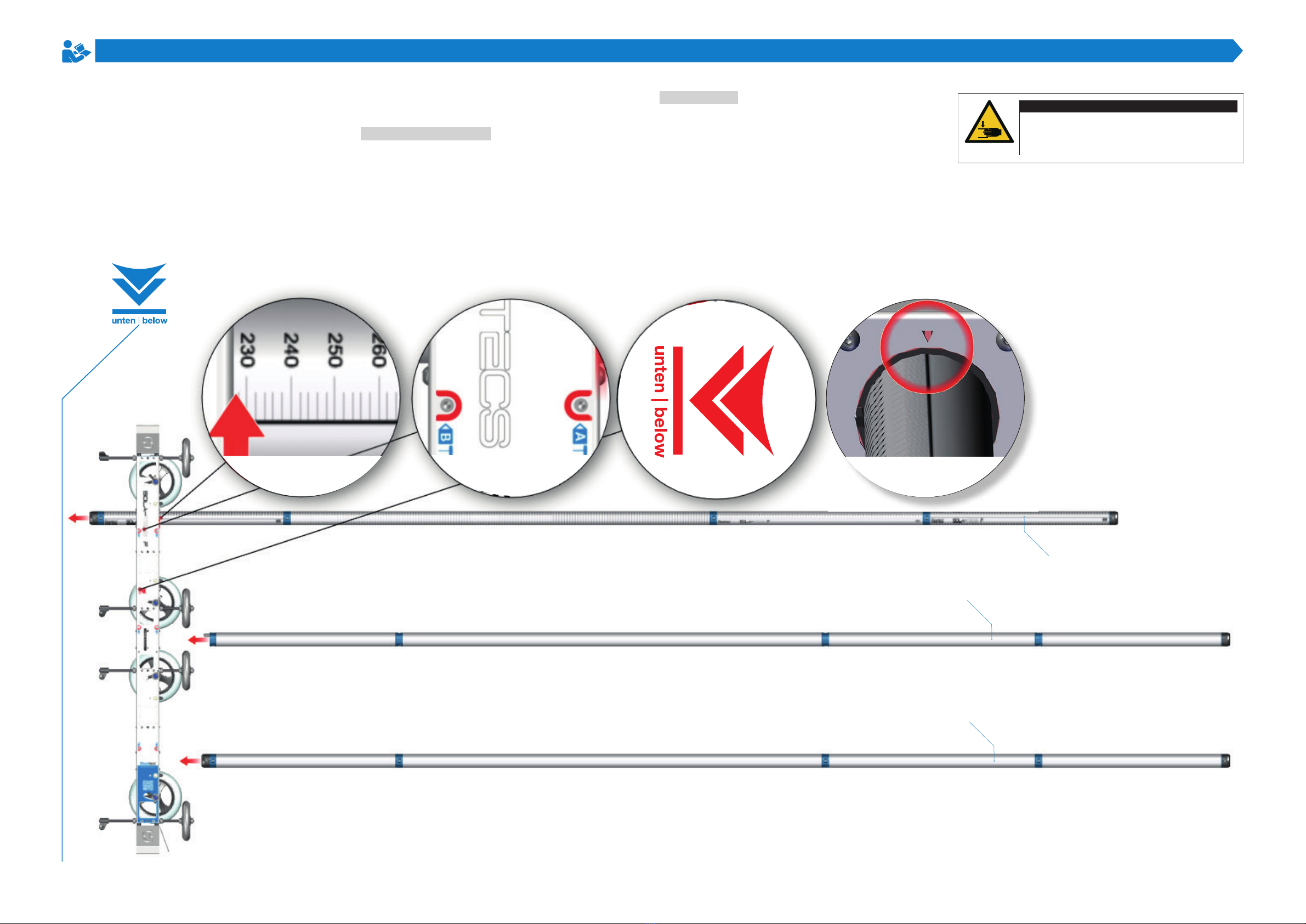
Mounting the
connecting tubes on
the lower carriage
The assembled connecting tubes must be mounted on
the lower [1] carriage first. To do this, position the lower
carriage [bottom] in front of the connecting tubes. Hexagon
socket 4 is required to clamp the [VR1] and [VR2] connec-
ting tubes. The hexagon socket 5 is required for the [VR3].
Mount VR1 and VR3:
Insert the hexagon socket 4 into the red mark [2] [A] until
it sits in the screw head. Insert the [VR1] into the pipe
duct up to 230 mm [3]. Align the line of the scale with
the triangle [4] on the carriage. Tighten the screw until
the [VR1] can no longer be turned (by hand). Tighten the
second screw at the mark [B] in the same way. Repeat this
procedure for [VR3] and the [E], [F] marks.
Mount VR2:
Insert the hexagon socket 5 into the red mark until it sits in
the screw head [C]. Insert the [VR2] into the pipe duct up to
230 mm. Align the continuous line of the scale with the [4]
triangle on the carriage. Tighten the screw until the [VR2]
can no longer be turned (hand-tight). Tighten the second
screw at the mark [D] in the same way.
[VR1]
[VR2]
[VR3]
AWear gloves during assembly.
This protects your skin from abrasions and
pinching.
WARNING
Risk of injury during assembly
[2] [3] [4]
[1][3]

12
MA 0302506 R00 2019-07
Construction
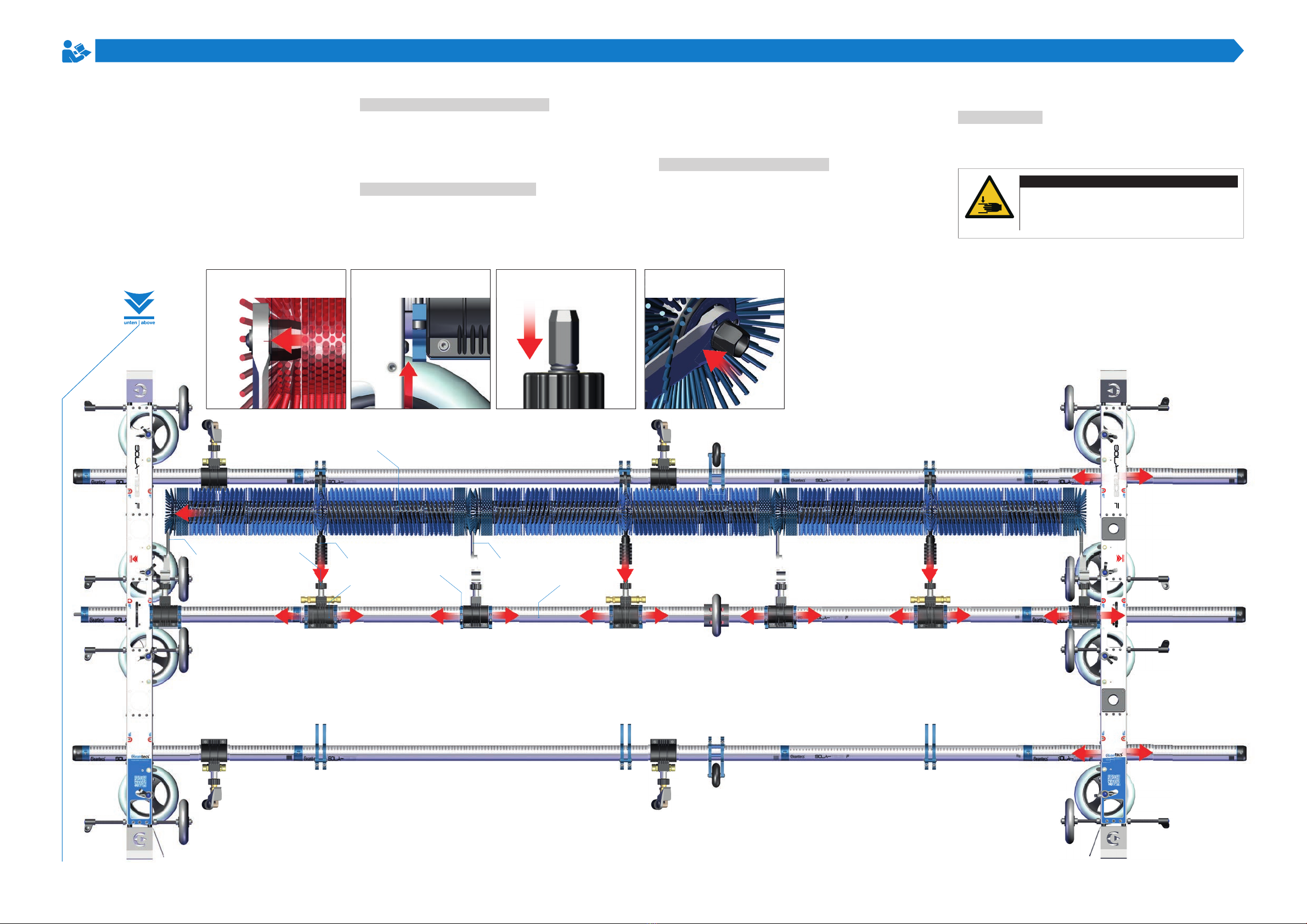
Preparing the
attachments
Check attachments for completeness and damage to avoid
problems during mounting. For a better overview: Place the
connecting tube attachments where they are to be moun-
ted. Pay attention to the correct quantity and order.
VR1 and VR3 attachments:
The same attachments are fitted to the connecting tubes
[VR1] and [VR2]. The attachments are each turned by 180°.
1. Brush stop [1] - the brush stop is always mounted oppo-
site the Sola-Tecs C. Its task is to make sure the Sola-Tecs
C follows the direction of the photovoltaic panels
2. Roll holder [2] - the roll holder supports the connecting
tube. It must be mounted from a structural length of 3200
mm.
3. SOLA-TECS F spray nozzle [3] – the spray nozzle cleans
the lower edges of the aluminum frames of photovoltaic
panels. It is mounted on each horizontal frame where a
lower edge is to be cleaned.
VR2 attachments:
The [VR2] connecting tube is used for all attachments
which hold and supply the Sola-Tecs C.
4. Counterholder [4] - the counterholder supports the free
end of the brush roller and reduces oscillation.
5. Clamping element [5] - the connection for the Sola-
Tecs C is located on the clamping element. The cleaner is
connected to the carrier system and supplied with high-
pressure water.
6. Guide bearing [6] - the guide bearing supports the end of
the brush roller and reduces oscillation.
7. Relief roller [7] - the relief roller supports the connecting
tube. It must be mounted from a structural length of 3200
mm.
8. Stop clamp [8] - the stop clamp determines the free
space available to the Sola-Tecs C to react to unevenness.
The stop clamps always come in front of and behind...
... the counterholders.
... the clamping elements.
... the guide bearings.
Installation position of add-on parts
[1]
[2]
[2]
[3]
[3]
[1]
[4]
[6]
[4]
[8]
[8]
[5]

13
MA 0302506 R00 2019-07
Construction
Assembly of the
attachments and the
upper carriage
The prepared attachments are now pushed onto the [VR1],
[VR2] and [VR3] connecting tubes and positioned and fixed
at the intended assembly point up to the required one.
Hexagon sockets 3 and 5 are required.
VR1 and VR3:
Push the spray nozzle [1] with the nozzle head to the [outsi-
de] position. Fix the spray nozzle in the mounting position
with hexagon socket 3 (page 12).
Push the brush stop [2] with the fork to the [inside] po-
sition. Fix the brush stop in the mounting position with
hexagon socket 5 (page 12).
Push the roll holder [3] with the wheel [outside] to the
middle of the structural length. Fix the roll holder in the
mounting position with hexagon socket 5 (page 12).
VR2:
Push the counter bearing [4] to the [outside] with the arm
and slide it into position together with the stop clamps. Fix
the stop clamps in the mounting position with hexagon so-
cket 5 (page 12).
Push the clamping element [5] to the [outside] with the
connection and slide it into the position together with the
stop clamps. Fix the stop clamps in the mounting position
with hexagon socket 5 (page 12).
Push the guide bearing [6] to the [outside] with the arm and
slide it into position together with the stop clamps. Fix the
stop clamps in the mounting position with hexagon socket
5 (page 12).
Place the relief roller [7] in the middle of the structural
length and fix it with hexagon socket 5.
[outside]
[4]
[5]
[5]
[5]
[7]
[2]
[2]
[1]
[1]
[2]
[2]
[1]
[1]
[1]
[1]
[2]
[2]
[3]
[3]
[6]
[6]
[4]
AWear gloves during assembly.
This protects your skin from abrasions and
pinching.
WARNING
Risk of injury during assembly
14
MA 0302506 R00 2019-07
Construction
Mounting the connec-
ting tubes on the top
carriage
After mounting the attachments, the [top] carriage [1] must
be mounted. Hexagon socket 4 is required to clamp the
[VR1] and [VR2] connecting tubes. The hexagon socket 5 is
required for the [VR3].
Mount VR1, VR2 and VR3:
Insert the [VR1], [VR2] and [VR3] into the pipe ducts. Push
the carriage onto the connecting tubes up to the counter
bearing. Insert the hexagon socket 4 into the red mark [A]
[2] until it sits in the screw head. Tighten the screw until
the [VR1] can no longer be turned (by hand). Tighten the
second screw at the mark [B] in the same way. Repeat
this procedure for [VR3] and the [E], [F] marks. Insert the
hexagon socket 5 into the red mark until it sits in the screw
head [C]. Tighten the screw until the [VR2] can no longer be
turned (hand-tight). Tighten the second screw at the mark
[D] in the same way. Check whether the line of the scale is
aligned with the [4] triangle on the carriage.
[VR1]
[VR2]
[VR3]
AWear gloves during assembly.
This protects your skin from abrasions and
pinching.
WARNING
Risk of injury during assembly
[2]
[2]
[4] [1]
15
MA 0302506 R00 2019-07
Construction
Mounting the
Sola-Tecs C
In this step, the Sola-Tecs C cleaning devices are installed.
Hexagon socket 5 is required for this. The construction
procedure is described from bottom to top. Before moun-
ting the cleaning brush, all stop clamps should be loosened
with the hexagon socket 5. For more assembly space, the
[top] carriage should be loosened again at the red mar-
kings.
Installation of the first cleaner:
Push the cleaner [1] onto the clamping element [2]. Tighten
the quick fitting [3] by hand. Thread the cleaner into the
counterholder [6] by moving the clamping element [2] and
the stop clamps [4] with the brush roller [5]. The counter
bearing [6] and the stop clamps [4] must be approx. 5 mm
from the carriage.
Assembly of second cleaner:
Thread the guide bearing [7] and the stop clamps [4] into
the brush roller [5] of the first cleaner [1] by moving it on
the connecting tube [VR2]. Push the second cleaner [1]
onto the clamping element [2]. Tighten the quick fitting [3]
by hand. Thread the cleaner into the guide bearing [7] by
moving the clamping element [2] and the stop clamps [4]
with the brush roller [5]. Thread the guide bearing [7] with
the stop clamps [4] into the brush roller [5] of the second
cleaner [1] by moving it on the connecting tube [VR2].
Installation of third cleaner:
Push the third cleaner [1] onto the clamping element [2].
Tighten the quick fitting [3] by hand. Thread the cleaner
into guide bearing [7] by moving the clamping element [2]
and the stop clamps [4] with the brush roller [5]. Thread the
counter bearing [6] with the stop clamps [4] into the brush
roller of the last cleaner by moving it on the connecting
tube [VR2].
Top carriage:
Clamp the carriage [top] at a distance of 5 mm from the
stop clamp [4] of the counter bearing [6] (page 14).
[6] + [5] [4] on the carriage [1] + [2] [5] + [7]
[1]
[7]
[6]
[2]
[VR2]
[3]
[4]
[5]
AWear gloves during assembly.
This protects your skin from abrasions and
pinching.
WARNING
Risk of injury during assembly

16
MA 0302506 R00 2019-07
Construction
Setting the working
width and assembly
of the lever
During this assembly step, the exact working width is set
and the clearance of the brush roller is fixed. To be able
to set the working width, the setting dimension must be
calculated. Measuring tape is required to do this. The hexa-
gon sockets 4 and 5 are required to fix the settings.
Determine the setting width:
To determine the setting width: Measure the cleaning
object vertically from the upper outer edge to the lower
outer edge to obtain the measurement of the cleaning
width [1]. To take the spring travel of the [bottom] carriage
into account, 2 cm must be subtracted from the measured
cleaning width. This will give you the setting dimension.
Setting the working width:
The horizontal wheels must be positioned in the unsprung
position [2]. Take the tape measure and measure the
distance [1] between the wheels [3] at the highest point
[inside]. Correct the dimension with the [top] carriage only.
When the correct dimension is set, clamp the [top] carriage
over the clamp points [C] and [D] on the [VR1] and [VR3].
Mounting the lever:
The lever [4] for the 180° flipping of the brush roller is
mounted on the [VR2]. The lever is mounted as described
on page 10. The lever position is not yet suitable for
flipping and must be corrected after assembly.
Correct lever position:
Release the [C] and [D] clamps on the [bottom] carriage.
Insert hexagon socket 4+5 into the clamping screw [C] of
the [bottom] and [top] carriages to prevent twisting of the
tube clamping unit. Move the lever 90° until it is parallel [5]
to the carriage. Re-fix the [bottom] and [top] carriages to
the [C] and [D] clamps.
Rough pre-positioning of the cleaners:
The cleaners must be pre-positioned to attach the Sola-
Tecs F to the photovoltaic system. Fix the stop clamps [6]
with the screws on [VR2]. Fix the brush stop [7] with the
screws on the [VR1] so that the head of the Sola-Tecs C
rests in the fork.
[VR2]
[1]
cleaning width
cleaning width mi-
nus 2 cm = Adjust-
ment dimension
[2] Above
[2] Below
[4]
[3]
[3]
[3]
[3]
[5] 90°
AWear gloves during assembly.
This protects your skin from abrasions and
pinching.
WARNING
Risk of injury during assembly
[6] [7]
[VR1]
[VR3]
[Inside]
[Inside]

17
MA 0302506 R00 2019-07
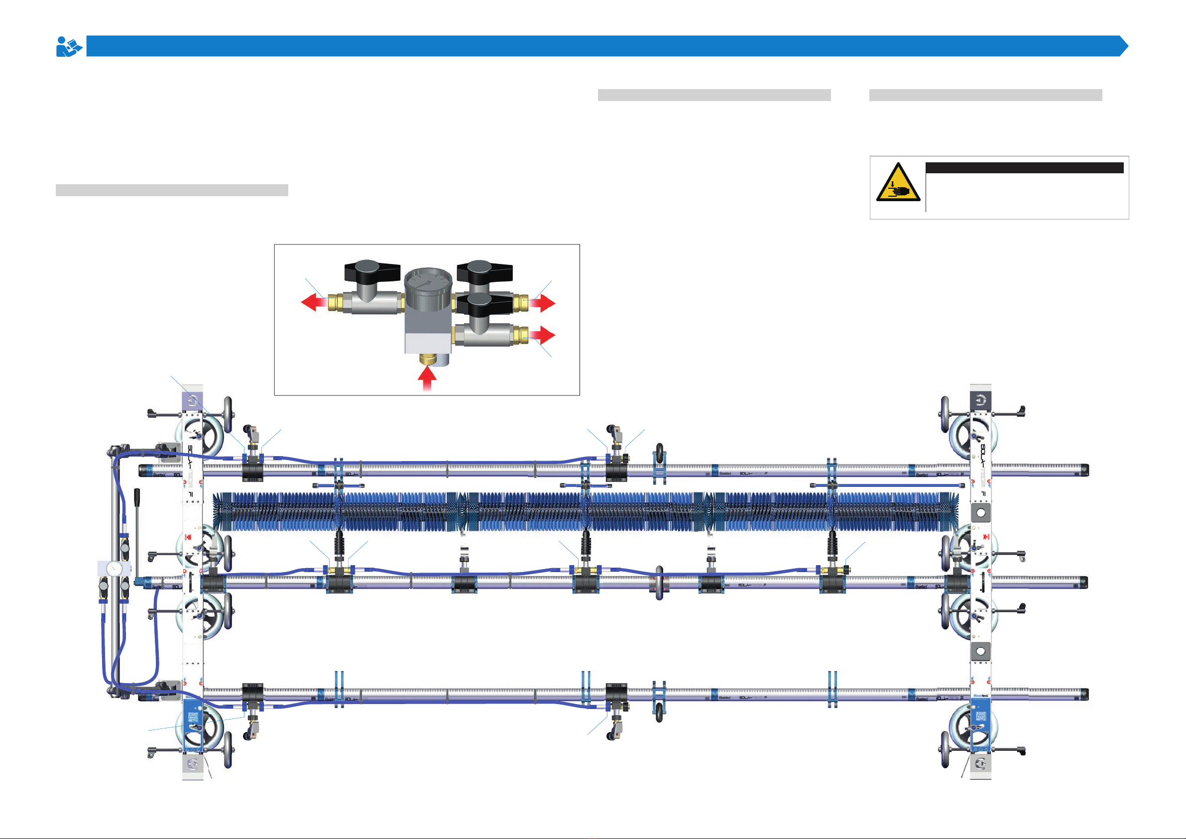
Construction
Mounting the
support frame, water
distributor and
distributor pipe
In this assembly step, the bottom support frame, the dis-
tribution pipes and the water distributor are mounted.
Hexagon socket 6 and the hose cutter are required. The
bottom support frame is delivered in pre-assembled indivi-
dual parts. The set consists of two carrying arms and a
handle tube. The distribution pipe is delivered in a length of
1500 mm and cut to the required length.
Mounting the support frame:
The support arms [1] are pushed onto [VR1] and [VR3].
Then, insert the handle tube [2] horizontally into the
connectors [3] and tighten the screws with the hexagon
socket 6. The clamp [4] must be fixed to the support arms
with hexagon socket 5 to attach it to the carriage. On the
angle connectors [5], the angle of the support arm can be
adjusted to the working height using the hexagon socket 6.
However, the angle should always be set so that the lever
for turning the brush roller can be actuated.
Mounting the water distributor:
The water distributor is mounted on the lower support arm.
To do this, unscrew the connector shells [6] and [7]. Loosen
the screw [10] with hexagon socket 6 and place the water
distributor on the handle tube. Make sure that the pressure
gauge [8] points upwards and the two connections [9] point
to the right. Then reattach the lower connector shell [7] to
the upper one [8]. Use the screws [10] for this purpose.
Tighten the two screws with the hexagon socket 6.
Cutting to size and assembly of distributor pipe:
The distributor tube for the Sola-Tecs C on the top carriage
must reach to the end of the brush roller [11]. The distribu-
tion pipe for the remaining connections should be approx.
150 mm [12] long. The cut distributor pipes are inserted
into the quick coupling [13]. The IQS closing cap [14] is
fitted to close the open side of the distributor pipe.
AWear gloves during assembly.
This protects your skin from abrasions and
pinching.
WARNING
Risk of injury during assembly
[14]
[13]
[5]
[3]
[1]
[4]
[6]
[7]
[10]
[2]
[8]
[9]
≈ 150 mm until the end brush roll
[11]
[12]
18
MA 0302506 R00 2019-07
Aufbau
Mounting the high-
pressure hoses
In this assembly step, the high-pressure hoses are laid and
assembled. Tools are not required for assembly. The Velcro
cable ties are required to secure the high-pressure hoses.
Mounting high-pressure hoses on the VR2:
The high-pressure hoses supply the system with water and
drive energy. The high-pressure hose of 2000 mm is scre-
wed onto the water distributor connection [1]. The high-
pressure hose is then laid under the carriage to connection
[2] of the first clamping element and screwed on. The
high-pressure hose of 1000 mm is laid and screwed from
connection [3] of the second clamping element along the
connecting tube to connection [4] of the following clamping
element. Depending on the structural width, the following
clamping elements are connected directly to high-pres-
sure hoses. The M22x1.5 plug [5] is screwed onto the free
connection of the last clamping element. The high-pressure
hoses are prevented from hanging down with the Velcro
cable ties on the connecting tube.
Mounting high-pressure hoses on the VR1:
The 1000 mm high-pressure hose is screwed to the water
distributor connection [6] and laid and screwed onto the
carriage to connection [7] of the first spray nozzle. Ano-
ther 1000 mm or 1500 mm high-pressure hose is screwed
to the connection [8] of the first spray nozzle. The high-
pressure hose is laid and screwed along the connecting
tube to the connection [9] of the second spray nozzle. The
M22x1.5 plug [5] is screwed onto the free connection of
the last clamping element. The high-pressure hoses are
prevented from hanging down with the Velcro cable ties on
the connecting tube.
Mounting high-pressure hoses on the VR3:
The 1000 mm high-pressure hose is screwed to the water
distributor connection [10] and laid and screwed over the
carriage to the connection [11] of the spray nozzle. The
remaining high-pressure hoses are laid as on [VR1].
AWear gloves during assembly.
This protects your skin from abrasions and
pinching.
WARNING
Risk of injury during assembly
[2]
[7]
[10]
[4]
[9]
[11]
[3]
[8]
[5]
[5]
[1]
[6]
[10]

19
MA 0302506 R00 2019-07
Construction
Mounting the top
support frame
In this assembly step, the partially pre-assembled support
frame for the top carriage will be mounted and attached to
the carriage. Hexagon socket 6 is required for mounting.
Mounting the top support frame:
Place the support tubes [1] and [2] with the cross holes [3]
facing [down] parallel to the mounting surface. Take the
stiffener [4]. Thread the stiffener with the connectors [5],
[6] from [down] onto the support tubes [1] and [2]. Slide
the stiffener 30 cm onto the support tubes. Align the holes
horizontally to the mounting surface. Tighten the screws on
the connectors [5] and [6]. Take the handle tube [7]. Thread
the grip tube [7] onto the carrier tubes with the connectors
[8] and [9]. Push the grip tube [7] onto the carrier tubes [1]
so far that you reach the top position for placing the Sola-
Tecs F upright. Tighten the screws on the connectors [8]
and [9]. Take the spring pins [10] and insert them into the
cross hole [3].
Mounting the top support frame on the carriage:
The carriage [top] is lifted. The support frame is inserted
into the holder [11] and [12] from below. The Sola-Tecs F
can be stored ready for use with a support frame.
AWear gloves during assembly.
This protects your skin from abrasions and
pinching.
WARNING
Risk of injury during assembly
[1]
[2]
[7]
[9]
[8]
[6]
[5]
[4]
[10]
[3]
[11]
[12]
20
MA 0302506 R00 2019-07
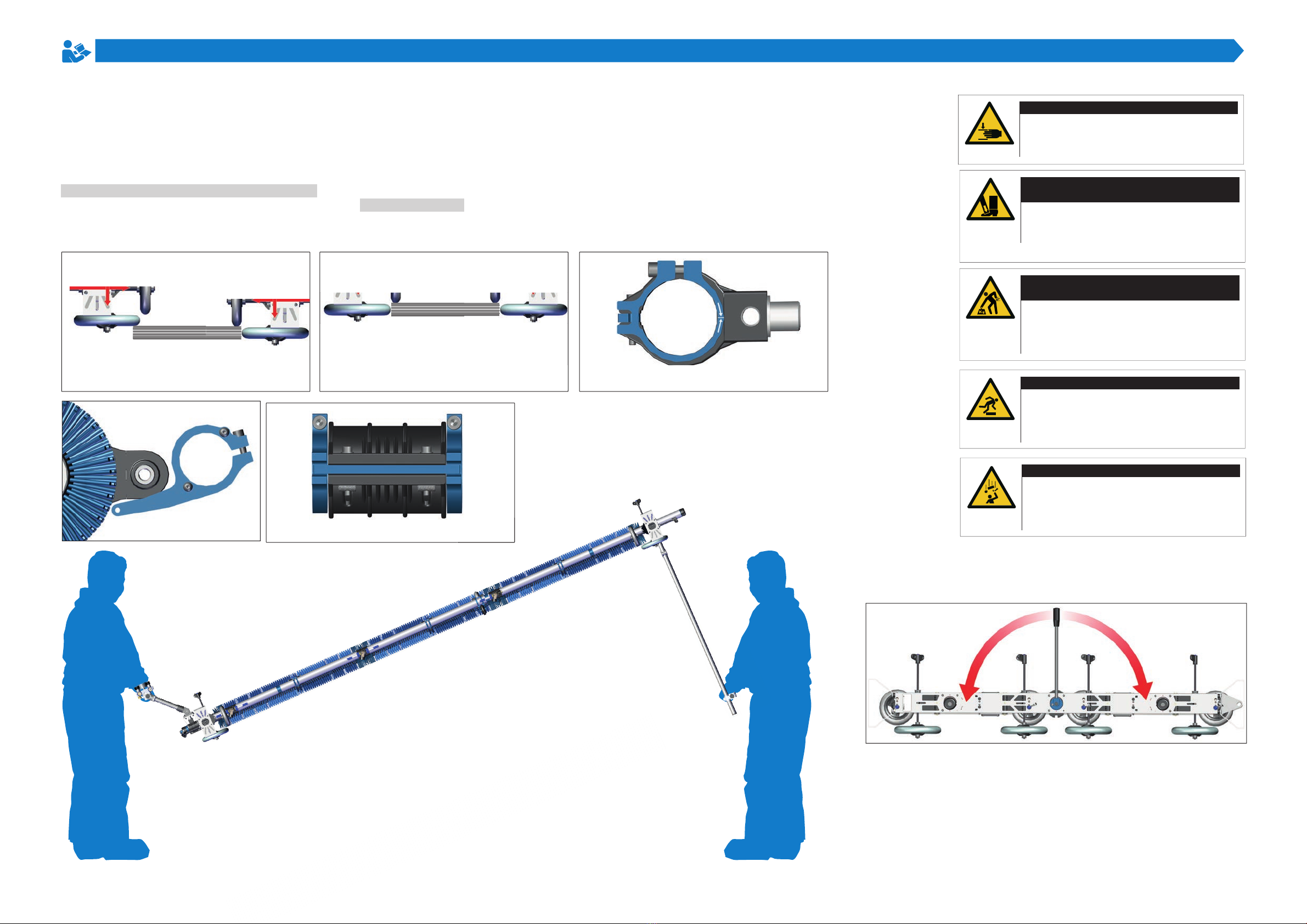
Construction
Set Sola-Tecs C on the
photovoltaic panels
In this last assembly step, the Sola-Tecs C is set to the
working height. Hexagon socket 5 is required for this.
Place Sola-Tecs F on photovoltaic panels:
Twp people are needed to set up the Sola-Tecs F system.
One person carries the system on the lower carrying
handle, one person carries it on the upper carrying hand-
le. Lift the system at the same time. Place the system on
the photovoltaic panels from the front of the system. Make
sure that the wheels of the [upper] carriage are in contact
with the frame first [1]. Let the wheels of the [bottom]
carriage rest on the photovoltaic panels 5. Pull the wheels
of the [bottom] carriage towards the carriage [1] so that the
wheels rest on the outside of the frame. Adjust the top and
bottom wheels vertically so that they are positioned in the
middle [2] of the frame.
Set Sola-Tecs C:
Loosen all the stop clamps on the [VR2] with hexagon
socket 5. Adjust the stop clamps as shown in figures [3]
and [4] and fix them again. Loosen the brush stop on the
[VR1] with the hexagon socket 5. Adjust and fix the brush
stops as shown in figure [5]. Hit the brush roller 180° using
the lever [6]. Loosen the brush stop on the [VR3] with the
hexagon socket 5. Adjust and fix the brush stops as shown
in figures [3] and [4].
AWear gloves during assembly.
This protects your skin from abrasions and
pinching.
WARNING
Risk of injury during assembly
[2]
Laufwagen unten
Laufwagen oben
[3] [4]
[6]
[7]
[1] [1]
AMake sure to lift the machine ergonomically.
This protects you from injuries caused by
straining your back.
WARNING
Risk of injury when lifting heavy parts
ACheck that the machine is positioned
correctly.
This protects you from injuries caused by the
machine falling down.
WARNING
Risk of injury due to falling machine
ACheck your work area for bumps and
obstacles.
This protects you from injuries caused by
falling.
WARNING
Risk of injury due to falling
[5]
ACheck the area to be cleaned for parts that
can fall off.
This protects you from injuries caused by
falling parts.
WARNING
Risk of injury due to falling parts
This manual suits for next models
3
Table of contents
Popular Cleaning Equipment manuals by other brands


Strava
Strava 100.600 user manual

Elma
Elma Elmasonic xtra ST operating instructions

HydraMaster
HydraMaster DriMaster II HiFlo owner's manual

Dane Technologies
Dane Technologies QuicKLEEN Owner's manual & operating instructions

Kärcher
Kärcher Puzzi 8/1 instruction manual

Streamline
Streamline DRAGONFLY4-OV8-25 instruction manual