HydraMaster DriMaster II HiFlo User manual

DriMaster II HiFlo Stainless
Steel Upholstery Tool
Owner’s Manual
HydraMaster North America, Inc.
11015 47th Avenue West, Mukilteo, Washington 98275
MAN-33278 Rev. 0, December 31, 2009
(182-803)
No part of this manual may be reproduced or used in any form or by any means (i.e. graphic, electronic, photocopying
or electronic retrieval systems) without the express written permission of HydraMaster North America, Inc.
All rights reserved. © 2009 HydraMaster North America, Inc.

Table of Contents
GENERAL INFORMATION........................................................................... SECTION 1
Contact Information................................................................................. 1-2
Warnings, Cautions and Notices............................................................. 1-3
OPERATING INSTRUCTIONS..................................................................... SECTION 2
Optional Accessory Handle Assembly..................................................... 2-1
Begin Cleaning........................................................................................ 2-2
TOOL MAINTENANCE................................................................................. SECTION 3
Removing and Re-installing the Clear Window Cover ............................ 3-1
Cleaning the Solution Bar Jet.................................................................. 3-2
Cleaning the Filter Cartridge and Orice Plate........................................ 3-3
ASSEMBLIES ANDPARTS LISTS................................................................ SECTION 4
DriMaster II HiFlo Stainless Steel Upholstery Tool Assembly Parts List . 4-3
Accessory Handle Assembly Parts List................................................... 4-4
Hide-A-Hose Stainless Steel Hose Assembly Parts List......................... 4-7
HOW TO ORDER PARTS ............................................................................ SECTION 5
Warranty Parts Orders ............................................................................ 5-1
Parts Orders............................................................................................ 5-1
Emergencies ........................................................................................... 5-1
WARRANTY INFORMATION ....................................................................... SECTION 6
DriMaster II HiFlo Stainless Steel Upholstery Tool Owner’s Manual - ii

List of Figures
Figure 1-1. DriMaster II HiFlo Stainless Steel Upholstery Tool ..............................1-1
Figure 1-2. Optional Accessory Handle Attached to Tool.......................................1-1
Figure 2-1. Remove Tool Screws...........................................................................2-1
Figure 2-2. Attach Accessory Handle.....................................................................2-1
Figure 2-3. Attach Solution Hose and Adjust Water Volume ..................................2-2
Figure 2-4. Turning Knob to “HiFlo” Position
Forms Sheet of Water Across Bar Jet .................................................2-3
Figure 3-1. Remove Tool from Hose ......................................................................3-1
Figure 3-2. Remove Solution Control Knob ...........................................................3-1
Figure 3-3. Remove All Screws on Tool .................................................................3-1
Figure 3-4. Separate Tool in Half ...........................................................................3-1
Figure 3-5. Re-install Clear Window Cover............................................................3-2
Figure 3-6. Clean the Solution Bar Jet...................................................................3-2
Figure 3-7. Disassemble Solution Quick Connect..................................................3-3
Figure 3-8. Remove Filter Cartridge and Plate Orice...........................................3-3
Figure 3-9. Re-assemble Solution Quick Connect.................................................3-3
Figure 4-1. DriMaster II HiFlo Stainless Steel
Upholstery Tool Assembly - Overview .................................................4-1
Figure 4-2. DriMaster II HiFlo Stainless Steel
Upholstery Tool Assembly - Parts View ...............................................4-2
Figure 4-3. Accessory Handle Assembly................................................................4-4
Figure 4-4. Hide-A-Hose Stainless Steel Hose Assembly - Parts View 1 of 2 .......4-5
Figure 4-5. Hide-A-Hose Stainless Steel Hose Assembly - Parts View 2 of 2 .......4-6
iii - DriMaster II HiFlo Stainless Steel Upholstery Tool Owner’s Manual

1-1: General Information
Congratulations on purchasing the very latest in upholstery cleaning technology.
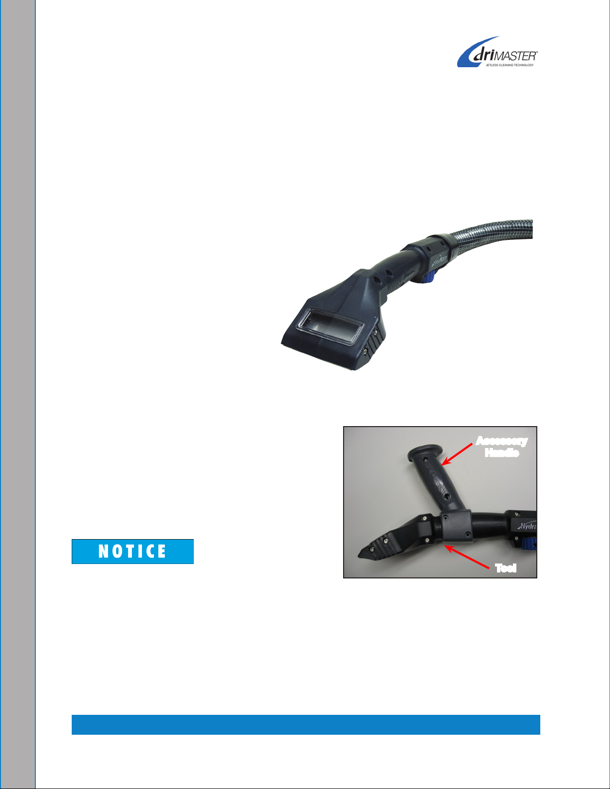
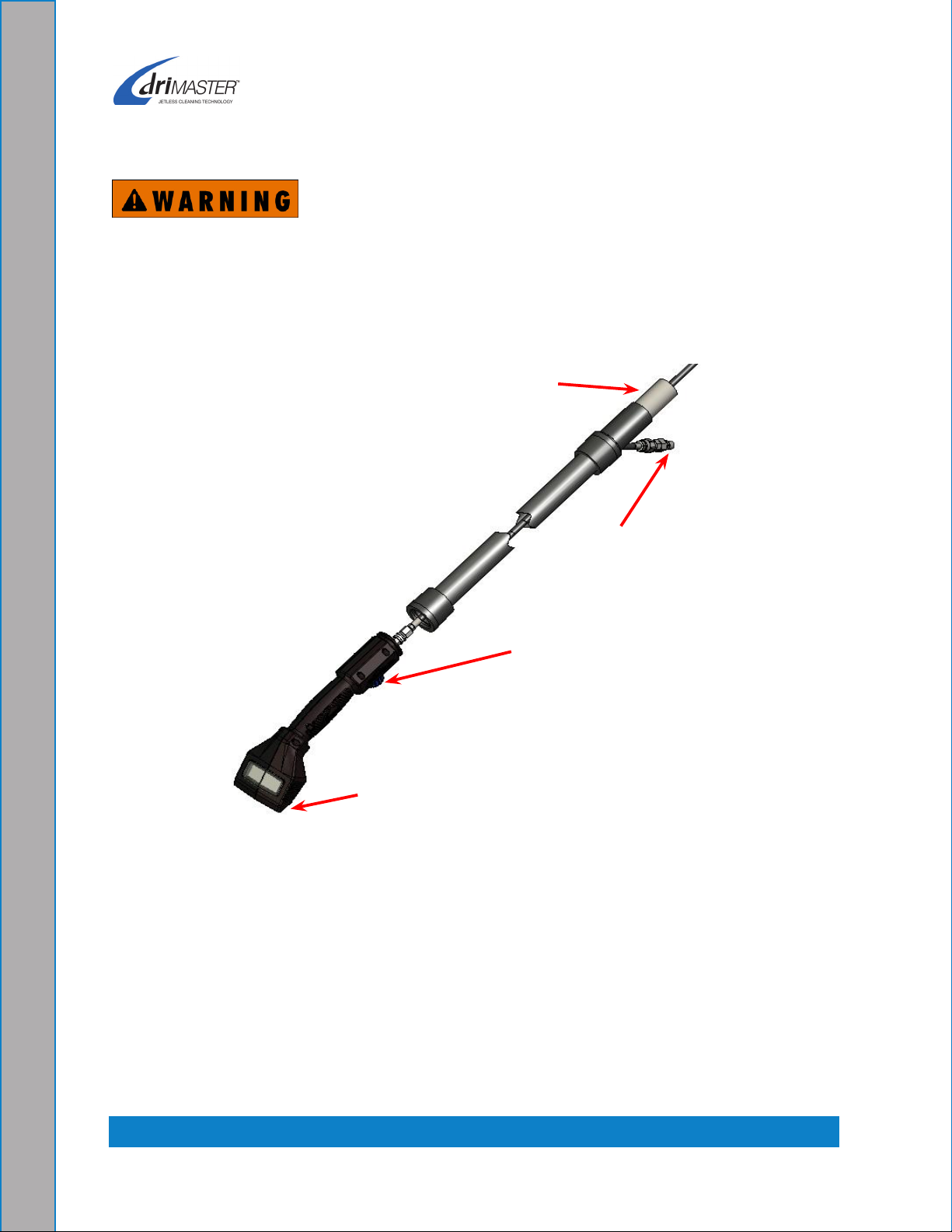
The patented DriMaster II HiFlo Stainless Steel Upholstery Tool, shown in Figure 1-1,
is perfect for cleaning upholstery, fabric and stairs. Because of its Jetless Cleaning
Technology, it has no trigger valve, no spray jet and never needs a separate dry pass.*
The tool’s new design incorporates
light weight, extremely durable
materials, giving the tool increased
levels of strength and comfort.
The DriMaster II HiFlo Stainless Steel
Upholstery Tool accommodates high
volume jobs where production rate is
important.
It is capable of solution ow rates
for jobs that require a ushing action
which makes the tool particularly
efcient for stair cleaning.
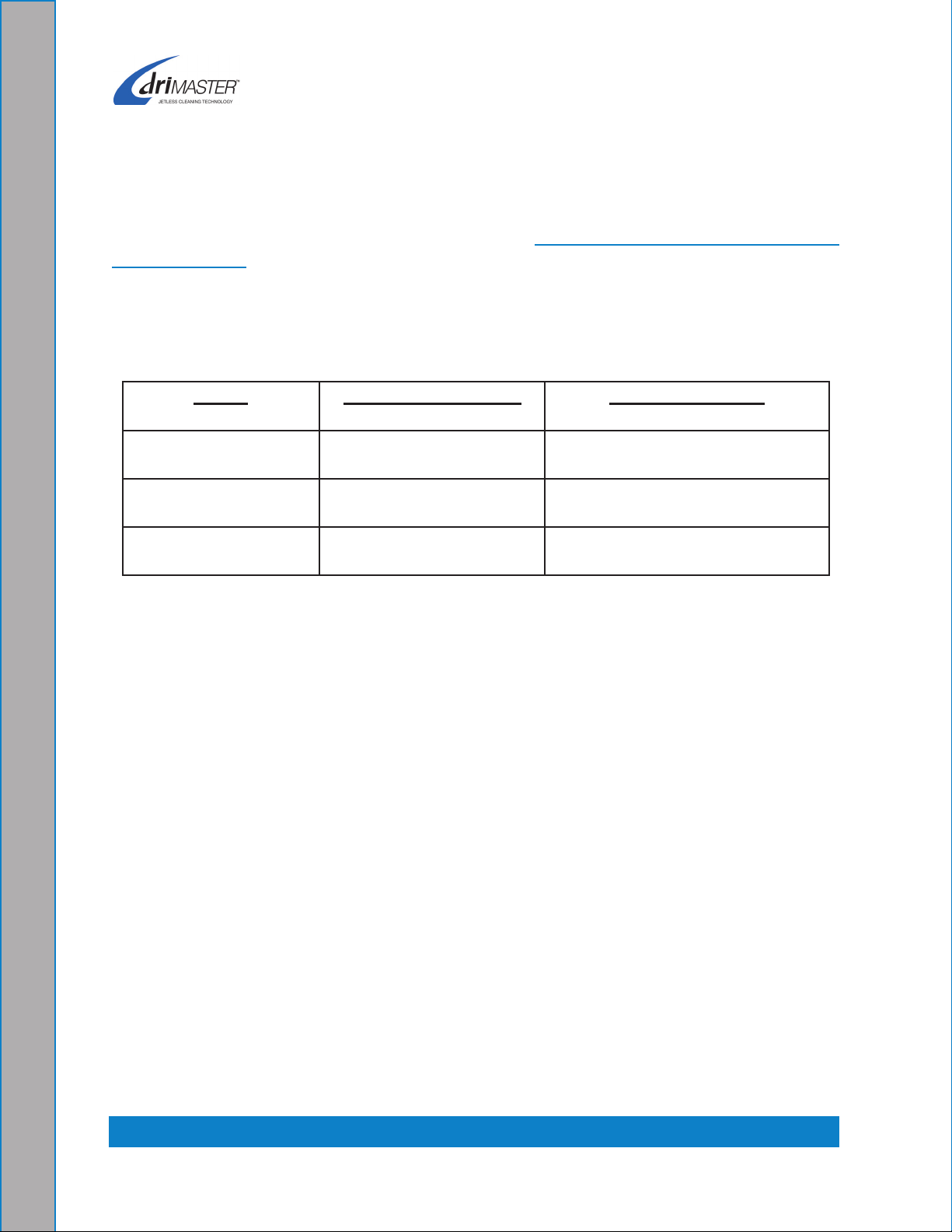
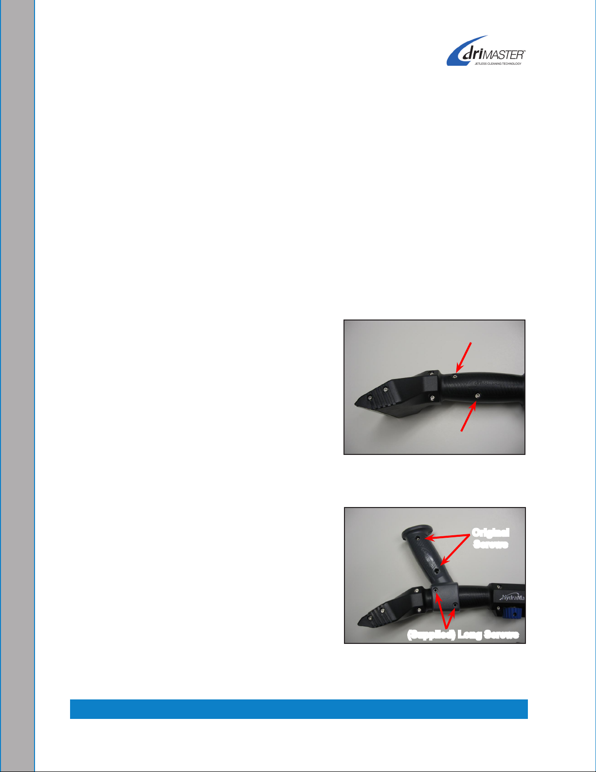
An optional accessory handle, shown attached
to the tool in Figure 1-2, is available to increase
comfort on long cleaning jobs.
We trust that you will enjoy many years of reliable
upholstery cleaning with the DriMaster II HiFlo
Stainless Steel Upholstery Tool.
The DriMaster II HiFlo Stainless Steel
Upholstery Tool can be used with a variety of
HydraMaster cleaning systems.
*U.S. Patent No. 6,243,914; 7,070,662; RE39,623; D590,111
New Zealand Patent No. 549645
Other U.S. and Foreign Patents Pending
1 - General Information
Figure 1-1. DriMaster II HiFlo
Stainless Steel Upholstery Tool
Accessory
Handle
Tool
Figure 1-2. Optional Accessory
Handle Attached to Tool

General Information: 1-2
CONTACT INFORMATION
If you have any questions regarding the operation, maintenance or repair of this tool,
please contact your local distributor.
To nd a local distributor, please visit our website at http://www.hydramaster.com/owners/
locate/index.asp.
If your question cannot be resolved by your distributor or by the information within this
manual, you may contact HydraMaster Customer Service direct using the following phone
numbers.
Hours Telephone Numbers E-mail Addresses
Monday-Friday (425) 775-7275 Service Tech Support:
techsupport@hydramaster.com
7:00 a.m. to 5:00 p.m. (425) 775-7276 Parts Parts Support:
partssupport@hydramaster.com
Pacic Standard Time (800) 426-4225 Parts /
Service FAX
FOR YOUR REFERENCE:
Date of Purchase:_____________________________________________
Purchased From (Distributor): __________________________________

1-3: General Information
WARNINGS, CAUTIONS AND NOTICES
HydraMaster uses this WARNING symbol throughout the manual to warn of
possible injury or death.
This CAUTION symbol is used to warn of possible equipment damage.
This NOTICE symbol indicates that federal or state regulatory laws may apply,
and also emphasizes supplemental information.

2-1: Operating Instructions
2 - Operating Instructions
Your DriMaster II HiFlo Stainless Steel Upholstery Cleaning Tool has been engineered
using the latest and most sophisticated technology available to produce the nest
upholstery cleaning results possible. Despite this, it remains only a tool of the upholstery
cleaning trade and can produce only as a good a job as the person operating it.
HydraMaster strongly recommends attending an Institute of Inspection, Cleaning
and Restoration Certication (IICRC) approved Upholstery Cleaning course as
soon as possible and to always follow the IICRC guidelines when cleaning.
OPTIONAL ACCESSORY HANDLE ASSEMBLY
The DriMaster II HiFlo Stainless Steel tool can be equipped with an optional accessory
handle (purchased separately) to increase comfort and control during difcult or extended
repetitious use of the upholstery tool.
Remove the two screws, nuts, and washers1.
found on the handle grip portion of the tool
(Figure 2-1). These parts will be reused in
fastening the handle.
Attach the accessory handle as shown in2.
Figure 2-2. The original shorter screws, nuts,
and washers are used on the upper handle.
The longer supplied screws, nuts and washers
are used to connect the handle to the tool
body.
Figure 2-1. Remove Tool
Screws
Figure 2-2. Attach Accessory
Handle
Original
Screws
(Supplied) Long Screws

Operating Instructions: 2-2
BEGIN CLEANING
Do not use the DriMaster II HiFlo Stainless Steel Upholstery Tool on a machine
exceeding 14” Hg vacuum and 500 psi solution pressure. Personal injury could
result.
Attach the solution hose to the solution quick connect. A 1 ½” - 2” vacuum hose can1.
be attached to the vac hose manifold (see Figure 2-3).
Adjust the water volume by turning the solution control knob. Turning the knob2.
counterclockwise increase the water volume; turning the knob clockwise decreases
the water volume. The amount of water volume you need will vary with the type of
machine you are cleaning with and the type of material you are cleaning.
To begin adjustment, make sure the cleaning machine is running and both vacuum3.
and solution hoses are connected.
Slowly open the solution control knob until water is owing across the entire bar jet 4.
(without overspray).
Figure 2-3. Attach Solution Hose and Adjust Water Volume
Solution Bar Jet
Solution Control Knob
Solution Quick
Connect
Vac Hose Manifold

2-3: Operating Instructions
When the solution knob is turned toward the
“HiFlo” position, the water will form a sheet across
the solution bar jet (see Figure 2-4).
The amount of vacuum and pressure produced
by your machine will determine the overspray
on the solution bar jet. The patented solution
bar jet makes a trigger valve unnecessary.
Do not touch the solution bar jet during
operation or immediately afterward; doing so
may cause severe burns!
When cleaning stairs, do not allow the tool to come into contact with the tack strip
along the edges of the stairs. The tool’s cleaning surface will be damaged by the
tack strip. Equipment damage such as this is not covered by warranty.
It may be necessary to periodically clean the inside of the tool, hose and manifold.
Debris can build up over time, restricting the vacuum ow (see Figure 3-6).
Figure 2-4. Turning Knob to
“HiFlo” Position Forms Sheet of
Water Across Bar Jet

3-1: Tool Maintenance
REMOVING AND RE-INSTALLING THE CLEAR WINDOW COVER
Remove vacuum hose cuff from1. DriMaster II HiFlo Stainless Steel Upholstery Tool
and disconnect the solution hose quick connect as shown in Figure 3-1.
Lightly heating the “cuff” with a heat gun will make the cuff easier to remove and
install.
Remove the solution control knob by removing the 8/32” Allen head screw as shown2.
in Figure 3-2.
Loosen, but do not remove, the valve retention nut (see arrow in3. Figure 3-3).
Remove all screws from both sides of the tool (see4. Figure 3-3) and carefully separate
the tool halves (see Figure 3-4).
3 - Tool Maintenance
Figure 3-3. Remove All Screws
on Tool
Figure 3-4. Separate Tool in Half
Valve Retention Nut
Figure 3-1. Remove Tool from
Hose
Figure 3-2. Remove Solution
Control Knob

Tool Maintenance: 3-2
Slide the clear window cover off of the tool5.
body.
To re-install the clear window cover, slide it6.
into one half of the tool body (see Figure 3-5).
Then slide the other half of the body into the
window.
The clear window has grooves on either side that slide
onto the edges of the cutouts in the tool bodies.
The wear plates must be aligned and slid onto the tool half at the same time as
the cover.
The window cover may come out if not installed properly.
Continue to assemble the two halves of the tool together, with the clear window7.
being captured in the cutouts. Careful attention must be paid when sliding the two
body halves together.
Re-install the screws.8.
Tighten the valve retention nut. Do not9.
overtighten.
CLEANING THE SOLUTION BAR JET
The solution bar jet needs to be cleaned with a .020”
feeler gauge.
Slide the feeler gauge into the small slot.1.
Gently slide the gauge back and forth to clear2.
any debris from the opening (see Figure 3-6).
Use only a feeler gauge to clean the slot in the bar
jet. Use of any other implement (paper clip, knife blade) may damage the opening
and seriously reduce the cleaning effectiveness of the upholstery tool.
Figure 3-5. Re-install Clear
Window Cover
Figure 3-6. Clean the
Solution Bar Jet

3-3: Tool Maintenance
HydraMaster recommends you clean the lter
cartridge and orice plate on a periodic basis
to eliminate hard water deposit buildup. Both
components are conveniently located in the
solution quick connect subassembly.
Disassemble the solution quick connect to gain access
to the lter cartridge and orice plate (see Figure 3-7
and Figure 3-8).
CLEANING THE FILTER CARTRIDGE
AND ORIFICE PLATE
Remove the lter cartridge and orice plate, place 1.
them in a cup full of white vinegar and soak for
30 minutes.
Clean the orice plate’s opening with a wooden 2.
skewer or similar tool such as a plastic pick.
Do not use a metal object to clean the opening of
the orice plate; doing so can damage the plate.
Remove both parts from the vinegar and3.
thoroughly rinse them with clear water.
Re-assemble the solution quick connect, re-4.
installing the lter cartridge and orice plate in the
proper order (see arrows in Figure 3-9).
Do not operate the DriMaster II HiFlo Stainless
Steel Upholstery Tool without the orice plate. If
you do not properly re-install the orice plate in the
solution quick connect (see Figure 3-9), equipment
damage could result. Such equipment damage is
not covered by warranty.
Figure 3-7. Disassemble
Solution Quick Connect
Figure 3-8. Remove Filter
Cartridge and Plate Orice
Orice Plate
Filter
Cartridge
Figure 3-9. Re-assemble
Solution Quick Connect

4-1: Assemblies and Parts Lists
4 - Assemblies and
Parts Lists
DriMaster II HiFlo Stainless Steel Upholstery Tool AssemblyFigure 4-1. -
Overview
7332

Assemblies and Parts Lists: 4-2
DriMaster II HiFlo Stainless Steel UpholsteryFigure 4-2.
Tool Assembly - Parts View
7332
1
3
2
7
9
14
9
16
15
9
16
9
9
10
10
10
11
14
9
13
6
5
8
4
12
17
REVISIONS
LTR
REVISION
CODE
DATE
BY
CHKD
APPVD
17 1
HOSE, HIDE-A-HOSE S.S. ASSEMBLY
VARIOUS
000-068-810
7331
16 6
CAPSCREW, SOCKET HEAD, 6-32 X 7/8
304
000-143-578
- - -
15 2
CAPSCREW, SOCKET HEAD, 6-32 X 3/4
304
000-143-577
- - -
14 4
CAPSCREW, SOCKET HEAD, 6-32 X 5/16
304
000-143-576
- - -
13 1
ASSEMBLY,KNOB CUSTOM INSERT WITH LABEL VARIOUS
000-061-146
7006
12 1
1/8" NPT X .1875" O.D.
316
000-052-781
- - -
11 1
COVER, DRIMASTER HIFLO, WINDOW
GE XYLEX
X8300
NA9A002
000-041-445
6950
10 8
NUT, NYLON LOCK 6-32
304
000-094-063
- - -
9 12
WASHER, FLAT, .248 O.D. X .128 I.D. X .029 THK
304
000-174-167
- - -
8 1
WASHER, FLAT, .875 O.D. X .515 I.D X .035 THK
304
000-174-768
- - -
7 1
HANDLE, HANDPIECE, RIGHT, DRIMASTER HIFLO
GE NORYL
PPX615-BK1005 000-061-139
6951
6 1
QUICK DISCONNECT, MALE 1/8" NPT
S.S. 000-052-783
- - -
5 1
1/8" NPT X 1.5
S.S. 000-052-782
- - -
4 1
VALVE, BALL S.S.
VARIOUS
000-169-222
- - -
3 1
HANDLE, HANDPIECE, LEFT, DRIMASTER HIFLO
GE NORYL
PPX615-BK1005 000-061-138
6952
2 2
PLATE, WEAR DRIMASTER HIFLO
304
000-076-084
6949
1 1
JET, DRIMASTER S.S. HIFLO BAR ASSEMBLY
S.S. 000-076-088
7711
ITEM NO.
QTY.
DESCRIPTION
MATERIAL PART NUMBER
DWG. NO.
D
C
B
A
A
B
C
D
1
2
3
4
5
6
7
8
8
7
6
5
4
3
2
1
E
F
E
F
MACHINE
FINISH
125
DRAWN
CHECKED
APPVD
SCALE: 1:2
SHEET 1 OF 1
DRAWING NUMBER
PROPRIETARY INFORMATION
11015 47th Avenue West,
Mukilteo, Washington 98275
D
SIZE
TOLERANCES
.X= .1
.XX= .03
.XXX= .010
ANGULAR= 1°
BREAK ALL SHARP EDGES 0.005-.015
UNLESS OTHERWISE NOTED
DIMENSIONS ARE IN INCHES
PART NUMBER
CODE:
APPLICATION
NEXT ASSY
USED ON
KW
LRK
11/05/2008
11/05/2008
11/05/2008
000-163-106
REV
TOOL, DRIMASTER S.S. HIFLO HANDPIECE ASSEMBLY
7332
LRK
- - -
- - -
HARRIS HIFLO
-
1
3
2
7
9
14
9
16
15
9
16
9
9
10
10
10
11
14
9
13
6
5
8
4
12
17
REVISIONS
LTR
REVISION
CODE
DATE
BY
CHKD
APPVD
17 1
HOSE, HIDE-A-HOSE S.S. ASSEMBLY
VARIOUS
000-068-810
7331
16 6
CAPSCREW, SOCKET HEAD, 6-32 X 7/8
304
000-143-578
- - -
15 2
CAPSCREW, SOCKET HEAD, 6-32 X 3/4
304
000-143-577
- - -
14 4
CAPSCREW, SOCKET HEAD, 6-32 X 5/16
304
000-143-576
- - -
13 1
ASSEMBLY,KNOB CUSTOM INSERT WITH LABEL VARIOUS
000-061-146
7006
12 1
1/8" NPT X .1875" O.D.
316
000-052-781
- - -
11 1
COVER, DRIMASTER HIFLO, WINDOW
GE XYLEX
X8300
NA9A002
000-041-445
6950
10 8
NUT, NYLON LOCK 6-32
304
000-094-063
- - -
9 12
WASHER, FLAT, .248 O.D. X .128 I.D. X .029 THK
304
000-174-167
- - -
8 1
WASHER, FLAT, .875 O.D. X .515 I.D X .035 THK
304
000-174-768
- - -
7 1
HANDLE, HANDPIECE, RIGHT, DRIMASTER HIFLO
GE NORYL
PPX615-BK1005 000-061-139
6951
6 1
QUICK DISCONNECT, MALE 1/8" NPT
S.S. 000-052-783
- - -
5 1
1/8" NPT X 1.5
S.S. 000-052-782
- - -
4 1
VALVE, BALL S.S.
VARIOUS
000-169-222
- - -
3 1
HANDLE, HANDPIECE, LEFT, DRIMASTER HIFLO
GE NORYL
PPX615-BK1005 000-061-138
6952
2 2
PLATE, WEAR DRIMASTER HIFLO
304
000-076-084
6949
1 1
JET, DRIMASTER S.S. HIFLO BAR ASSEMBLY
S.S. 000-076-088
7711
ITEM NO.
QTY.
DESCRIPTION
MATERIAL PART NUMBER
DWG. NO.
D
C
B
A
A
B
C
D
1
2
3
4
5
6
7
8
8
7
6
5
4
3
2
1
E
F
E
F
MACHINE
FINISH
125
DRAWN
CHECKED
APPVD
SCALE: 1:2
SHEET 1 OF 1
DRAWING NUMBER
PROPRIETARY INFORMATION
11015 47th Avenue West,
Mukilteo, Washington 98275
D
SIZE
TOLERANCES
.X= .1
.XX= .03
.XXX= .010
ANGULAR= 1°
BREAK ALL SHARP EDGES 0.005-.015
UNLESS OTHERWISE NOTED
DIMENSIONS ARE IN INCHES
PART NUMBER
CODE:
APPLICATION
NEXT ASSY
USED ON
KW
LRK
11/05/2008
11/05/2008
11/05/2008
000-163-106
REV
TOOL, DRIMASTER S.S. HIFLO HANDPIECE ASSEMBLY
7332
LRK
- - -
- - -
HARRIS HIFLO
-

4-3: Assemblies and Parts Lists
DriMaster II HiFlo Stainless Steel Upholstery Tool
Assembly Parts List
1 000-076-088 Jet, DriMaster S/S HiFlo Bar Assembly 1
2 000-105-533 Plate, Wear DriMaster 2
3 000-061-138 Handle, Handpiece, Left, DriMaster HiFlo 1
4 000-169-222 Valve, Ball S/S 1
5 000-052-782 1/8” NPT X 1.5 S. S. 1
6 000-052-783 Quick Disconnect, Male 1/8” NPT 1
7 000-061-139 Handle, Handpiece, Right, DriMaster HiFlo 1
8 000-174-768 Washer, Flat, .875 O.D. X .515 I.D X .035 Thk 1
9 000-174-167 Washer, Flat, .248 O.D. X .128 I.D. X .029 Thk 12
10 000-094-063 Nut, Nylon Lock 6-32 8
11 000-041-445 Cover, DriMaster HiFlo, Window 1
12 000-052-781 1/8” NPT X .1875” O.D. 1
13 000-061-146 Assembly, Knob Custom Insert With Label 1
14 000-143-576 Capscrew, Socket Head, 6-32 X 5/16 4
15 000-143-577 Capscrew, Socket Head, 6-32 X 3/4 2
16 000-143-578 Capscrew, Socket Head, 6-32 X 7/8 6
17 000-068-810 Hose, Hide-A-Hose S/S Assembly 1
Item Part Number Description Qty

Assemblies and Parts Lists: 4-4
Accessory Handle Assembly Parts List
Accessory Handle AssemblyFigure 4-3.
6958 Rev. B
1 000-061-142 Handle, Accessory, Right 1
2 000-061-141 Handle, Accessory, Left 1
3 000-174-167 Washer, Flat, 0.248” O.D. x 0.128” I.D. x 0.029” Thk 2
4 000-094-063 Nut, #6-32 Nyloc 2
5 000-143-579 Screw, #6-32UNC x 2” Lg. Socket Head 2
P/N 000-164-030 Allen wrench also included with the Accessory Handle Assembly.
Item Part Number Description Qty

4-5: Assemblies and Parts Lists
Hide-A-Hose Stainless Steel Hose Assembly - Parts View 1 of 2Figure 4-4.
7331 Rev. D
13
C
C
DETAIL A
10
8
7
5
3
6
1
2
9
1
120
±2
1.00
±0.25
2.50
±0.25
C
1 1
3
2
1
DETAIL B
11
12
4
4.00
±0.25
1.500
DETAIL C
SCALE 1 : 1
NOTES:
BOND WITH ADHESIVE, 3M
1.
SCOTCH WELD, DP 100
000-146-018
SWAGE, SYNFLEX
2.
PUSHER, 4599-MP-026
DIE, 4540-30200
SWAGE, SYNFLEX
3.
PUSHER, 4599-MP023
DIE, 4540-30200
D
REVISIONS
LTR
REVISION
CODE
DATE
BY
CHKD
APPVD
C
CORRECTED ORDER OF HARDWARE
IN EXPLODED VIEW. ADDED .217 NPT
THREAD ENGAGEMENT DIMENSION IN
MODEL BETWEEN ITEM 6 AND 7.
LRIP
4/20/2009
R.D.M.
L.R.K. L.R.K.
D
CORRECTED ITEM 7 NPT DIMENSION.
LRIP
4/27/2009
R.D.M.
L.R.K. L.R.K.
13 1
1.5" VAC HOSE - GRAY
VARIOUS
000-068-036
- - -
12 1
INSERT, 1/8" HOSE X 1/8" MNPT S/S
303 S.S.
000-052-810
- - -
11 1
SWIVEL CUFF - HALF
PVC, SYLVIN
9915-80
NATURAL
000-052-806
- - -
10 1
TUBE, 1.5" S.S - HIDE-A-HOSE
304 S.S.
000-125-248
7691
9 1
CUFF - SOLUTION HOSE 1/4" THRU
PVC, SYLVIN
9915-90
NATURAL
000-052-807
- - -
8 1
HOSE, 1/8" USP 540N-2
NYLON
000-068-811
- - -
7 1
INSERT, 1/8" HOSE X 1/4" MNPT S/S
303 S.S.
000-052-811
- - -
6 1
ADAPTER, S.S. JET X 1/4" FNPT
303 S.S.
000-052-804
- - -
5 1
ORIFICE, PLATE 0.067"
303 S.S.
000-180-024
- - -
4 1
QUICK CONNECT, FEMALE, 1/8" - OPEN
303 S.S.
000-052-805
- - -
3 1
FILTER CARTRIDGE, 1/4" SS
303 S.S.
000-049-253
- - -
2 1
QUICK CONNECT, 440 MALE W/ VITON STD
303 S.S.
000-052-516
- - -
1 1
HOUSING, 1/4" S.S. FILTER
303 S.S.
000-052-803
- - -
ITEM NO.
Defaul
t/QTY.
DESCRIPTION
MATERIAL
PART NO. DWG. NO.
D
C
B
A
B
C
D
1
2
3
4
5
6
7
8
8
7
6
5
4
3
2
1
E
F
E
F
A
D
REV
7331
4/9/2007
4/9/2007
4/5/2007
USED ON
NEXT ASSY
APPLICATION
CODE:
PART NUMBER
UNLESS OTHERWISE NOTED
DIMENSIONS ARE IN INCHES
BREAK ALL SHARP EDGES 0.005-.015
TOLERANCES
.X= .1
.XX= .03
.XXX= .010
ANGULAR= 1°
SIZE
C
11015 47th Avenue West,
Mukilteo, Washington 98275
PROPRIETARY INFORMATION
DRAWING NUMBER
SHEET 1 OF 1
SCALE: 1:2
APPVD
CHECKED
DRAWN
125
MACHINE
FINISH
KJW
LRK
LRK
- - -
000-068-810
HARRIS HIFLO
7332
- - - - - -
HOSE, HIDE-A-HOSE S.S. ASSEMBLY
See Figure 4-5 for details

Assemblies and Parts Lists: 4-6
Figure 4-5. Hide-A-Hose Stainless Steel Hose Assembly - Parts View 2 of 2
7331 Rev. D
13
C
C
DETAIL A
10
8
7
5
3
6
1
2
9
1
120
±2
1.00
±0.25
2.50
±0.25
C
1 1
3
2
1
DETAIL B
11
12
4
4.00
±0.25
1.500
DETAIL C
SCALE 1 : 1
NOTES:
BOND WITH ADHESIVE, 3M
1.
SCOTCH WELD, DP 100
000-146-018
SWAGE, SYNFLEX
2.
PUSHER, 4599-MP-026
DIE, 4540-30200
SWAGE, SYNFLEX
3.
PUSHER, 4599-MP023
DIE, 4540-30200
D
REVISIONS
LTR
REVISION
CODE
DATE
BY
CHKD
APPVD
C
CORRECTED ORDER OF HARDWARE
IN EXPLODED VIEW. ADDED .217 NPT
THREAD ENGAGEMENT DIMENSION IN
MODEL BETWEEN ITEM 6 AND 7.
LRIP
4/20/2009
R.D.M.
L.R.K. L.R.K.
D
CORRECTED ITEM 7 NPT DIMENSION.
LRIP
4/27/2009
R.D.M.
L.R.K. L.R.K.
13 1
1.5" VAC HOSE - GRAY
VARIOUS
000-068-036
- - -
12 1
INSERT, 1/8" HOSE X 1/8" MNPT S/S
303 S.S.
000-052-810
- - -
11 1
SWIVEL CUFF - HALF
PVC, SYLVIN
9915-80
NATURAL
000-052-806
- - -
10 1
TUBE, 1.5" S.S - HIDE-A-HOSE
304 S.S.
000-125-248
7691
9 1
CUFF - SOLUTION HOSE 1/4" THRU
PVC, SYLVIN
9915-90
NATURAL
000-052-807
- - -
8 1
HOSE, 1/8" USP 540N-2
NYLON
000-068-811
- - -
7 1
INSERT, 1/8" HOSE X 1/4" MNPT S/S
303 S.S.
000-052-811
- - -
6 1
ADAPTER, S.S. JET X 1/4" FNPT
303 S.S.
000-052-804
- - -
5 1
ORIFICE, PLATE 0.067"
303 S.S.
000-180-024
- - -
4 1
QUICK CONNECT, FEMALE, 1/8" - OPEN
303 S.S.
000-052-805
- - -
3 1
FILTER CARTRIDGE, 1/4" SS
303 S.S.
000-049-253
- - -
2 1
QUICK CONNECT, 440 MALE W/ VITON STD
303 S.S.
000-052-516
- - -
1 1
HOUSING, 1/4" S.S. FILTER
303 S.S.
000-052-803
- - -
ITEM NO.
Defaul
t/QTY.
DESCRIPTION
MATERIAL
PART NO. DWG. NO.
D
C
B
A
B
C
D
1
2
3
4
5
6
7
8
8
7
6
5
4
3
2
1
E
F
E
F
A
D
REV
7331
4/9/2007
4/9/2007
4/5/2007
USED ON
NEXT ASSY
APPLICATION
CODE:
PART NUMBER
UNLESS OTHERWISE NOTED
DIMENSIONS ARE IN INCHES
BREAK ALL SHARP EDGES 0.005-.015
TOLERANCES
.X= .1
.XX= .03
.XXX= .010
ANGULAR= 1°
SIZE
C
11015 47th Avenue West,
Mukilteo, Washington 98275
PROPRIETARY INFORMATION
DRAWING NUMBER
SHEET 1 OF 1
SCALE: 1:2
APPVD
CHECKED
DRAWN
125
MACHINE
FINISH
KJW
LRK
LRK
- - -
000-068-810
HARRIS HIFLO
7332
- - - - - -
HOSE, HIDE-A-HOSE S.S. ASSEMBLY

4-7: Assemblies and Parts Lists
Hide-A-Hose Stainless Steel Hose Assembly Parts List
Item Part Number Description Qty
1 000-052-803 Housing, 1/4" S/S. Filter 1
2 000-052-516 Quick Connect, 440 Male W/ Viton Std 1
3 000-049-253 Filter Cartridge, 1/4" S/S 1
4 000-052-805 Quick Connect, Female, 1/8" - Open 1
5 000-180-024 Orice, Plate 0.067" 1
6 000-052-804 Adapter, S/S. Jet X 1/4" FNPT 1
7 000-052-811 Insert, 1/8" Hose X 1/4" MNPT S/S 1
8 000-068-811 Hose, 1/8" USP 540n-2 1
9 000-052-807 Cuff - Solution Hose 1/4" Thru 1
10 000-125-248 Tube, 1.5" S/S - Hide-A-Hose 1
11 000-052-806 Swivel Cuff - Half 1
12 000-052-810 Insert, 1/8" Hose X 1/8" MNPT S/S 1
13 000-068-036 Hose - Gray, 1.5” Vac 1

5-1: How to Order Parts:
From time to time, cleaning equipment may wear out or malfunction. To obtain a proper
diagnosis of your malfunction, and to order warranty replacement parts or arrange for
repairs, it is important that you proceed in the following manner:
WARRANTY PARTS ORDERS
Call the local distributor where you purchased your equipment and ask for the1.
Service Department.
Have the following information ready:2.
Equipment Modela.
Date of Purchaseb.
Description of Malfunctionc.
Once it has been determined which parts are needed to correct the problem with3.
your tool, make arrangements with your distributor to either perform the repairs or
ship the parts to you.
PARTS ORDERS
Call your local distributor. In most instances, they either stock or have access to parts
through a regional service center.
EMERGENCIES
If, for any reason, your distributor is unable to supply you with the necessary parts, they
may call us and arrange for expedited shipping.
HydraMaster sells parts only through authorized distributors and service centers.
We shall always endeavor to be fair in our evaluation of your warranty claim, and shall
provide you with a complete analysis of our ndings.
5 - How to Order Parts
Table of contents
Other HydraMaster Cleaning Equipment manuals

HydraMaster
HydraMaster Steamatic 8800 TMU User manual

HydraMaster
HydraMaster Boxxer 318 User manual

HydraMaster
HydraMaster Titan 625 User manual

HydraMaster
HydraMaster CTS 403 Flex User manual

HydraMaster
HydraMaster CDS 4.8 User manual

HydraMaster
HydraMaster The Master's Touch TMT 3000 User manual

HydraMaster
HydraMaster DriMaster HiFlo User manual

HydraMaster
HydraMaster DriMaster Upholstery Tool User manual

HydraMaster
HydraMaster ChemDry CTS 400 Flex User manual