Sola VESTA-2813 SM User manual

VESTA-2813
SM / NS PLUS
WWW.SOLAGRUPO.COM
COMMISSIONING, MAINTENANCE AND DOSAGE
USER’S
MANUAL
Trailed pneumatic seed drill

- 2 -
SOLÀ Seed Drills and Fertilizer Spreaders are manufactured in a factory specialised exclusively in this seg-
ment and backed by the experience in use of many thousands of users.
They are high-tech machines designed for long, trouble-free service in a wide variety of conditions,
equipped with simple, eective devices for excellent performance with minimum maintenance.
Our goal in providing full information about its possibilities and settings is to help you achieve what you
expect from our machine.
2nd Edition - July 2019
Ref.: CN-811138/GB
Created by: MAQUINARIA AGRÍCOLA SOLÀ, S.L.
No part of this manual may be reproduced in any form.
Specications subject to change without notice.
The photographs do not necessarily show the standard version of the machine.

- 3 -
TABLE OF CONTENTS
1- INTRODUCTION .......................................................................................................................................................... 5
2. SAFETY INSTRUCTIONS ............................................................................................................................................. 6
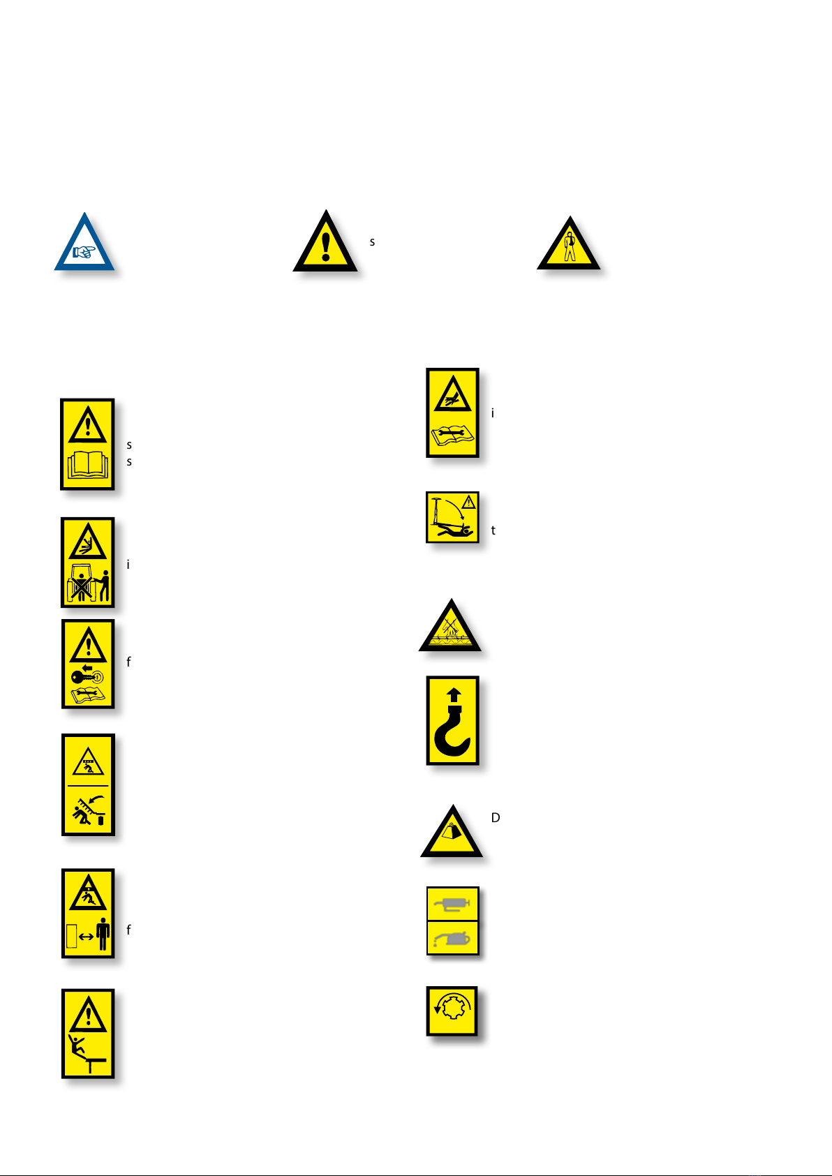
2.1 SAFETY SYMBOLS ....................................................................................................................................................................... 6
2.2 GENERAL SAFETY PROVISIONS ................................................................................................................................................ 7
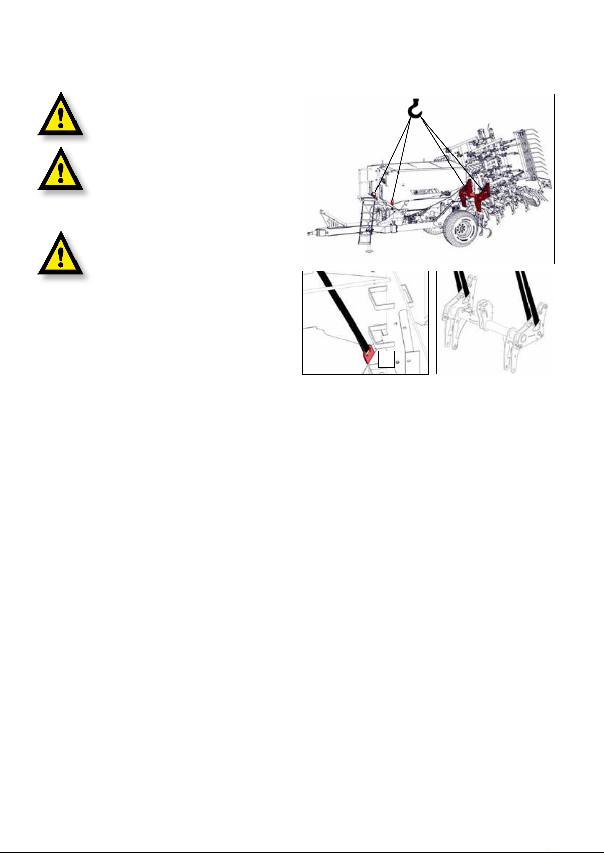
2.3 LOADING AND UNLOADING INSTRUCTIONS.......................................................................................................................... 8
3. GENERAL DESCRIPTION.............................................................................................................................................. 9
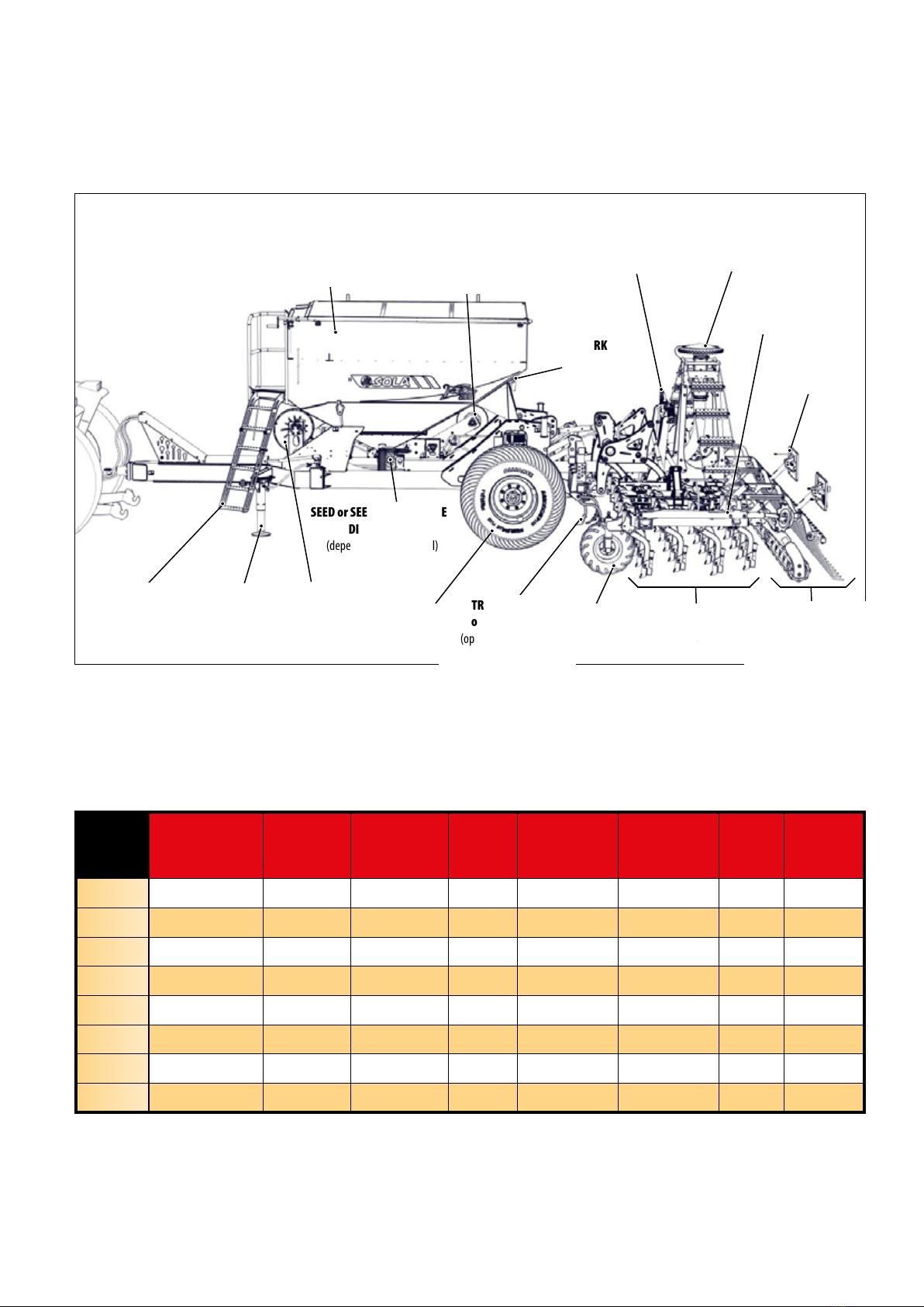
3.1 OVERVIEW OF THE MACHINE..................................................................................................................................................... 9
3.2 TECHNICAL SPECIFICATIONS ..................................................................................................................................................... 9
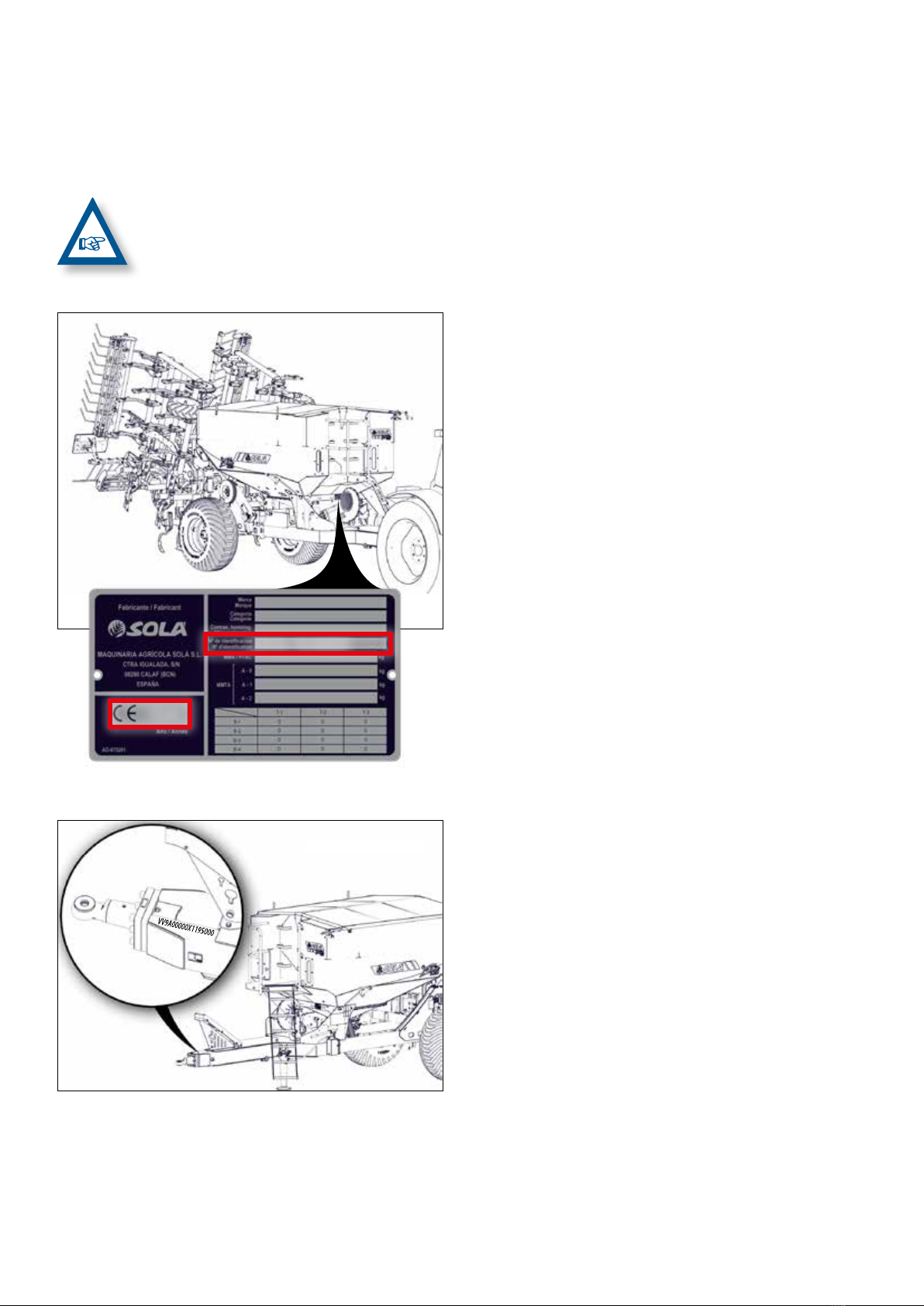
3.3 MACHINE IDENTIFICATION....................................................................................................................................................... 10
3.4 USE ACCORDING TO DESIGN ................................................................................................................................................... 10
4. KEY CONCEPTS FOR SOWING.................................................................................................................................... 11
4.1 SOIL .............................................................................................................................................................................................. 11
4.2 SEED ............................................................................................................................................................................................. 11
4.3 DEPTH .......................................................................................................................................................................................... 11
5. COMMISSIONING...................................................................................................................................................... 12
5.1 COUPLING THE SEED DRILL TO THE TRACTOR...................................................................................................................... 12
5.2 ELECTRICAL CONNECTIONS..................................................................................................................................................... 13
5.2.1 WORK LAMPS.................................................................................................................................................................... 13
5.2.2 SIGNALLING LIGHTS........................................................................................................................................................ 13
5.2.3 ISOBUS ............................................................................................................................................................................... 13
5.3 HYDRAULIC CONNECTIONS ..................................................................................................................................................... 13
5.4 TRANSPORT POSITION.............................................................................................................................................................. 15
5.5 LOADING AND EMPTYING THE HOPPERS.............................................................................................................................. 17
5.5.1 SEED/FERTILIZER HOPPER (depending on the model)............................................................................................. 18
5.6 SUPPORT LEGS ........................................................................................................................................................................... 22
5.6.1 FRONT SUPPORT LEG...................................................................................................................................................... 22
5.6.2 REAR SUPPORT LEG......................................................................................................................................................... 23
5.7 PARKING ...................................................................................................................................................................................... 24
5.8 END OF WORK WITH THE MACHINE........................................................................................................................................ 24
6. ADJUSTMENTS ......................................................................................................................................................... 25
6.1 LEVELLING THE COULTER UNIT ............................................................................................................................................... 25
6.2 DEPTH CONTROL ....................................................................................................................................................................... 25
6.2.1 DEPTH ADJUSTERS .......................................................................................................................................................... 27
6.2.2 DEPTH CONTROL WHEELS.............................................................................................................................................. 28
6.2.3 FOLDING PART ANGLE STOPS ....................................................................................................................................... 29
6.2.4 COULTERS.......................................................................................................................................................................... 29
6.2.4.1 SM MODEL............................................................................................................................................................... 30
6.2.4.2 NS PLUS MODEL (STRAIGHT COULTERS) ........................................................................................................... 31
6.2.4.3 NS PLUS MODEL (SUFFOLK COULTERS) ............................................................................................................. 31
6.3 DOSAGE ....................................................................................................................................................................................... 32
6.3.1 VOLUMETRIC DISPENSER ............................................................................................................................................... 32
6.3.1.1 REGULAR SEED OR CONVENTIONAL FERTILIZER............................................................................................. 33
6.3.1.2 FINE SEED OR MICROGRANULATE FERTILIZER................................................................................................. 34
6.3.2 ROLLER DISPENSER ......................................................................................................................................................... 35
6.3.3 DISPENSERS FOR FERTILIZER AND/OR MICROGRANULATOR KITS......................................................................... 36
6.3.3.1 INTERNAL KIT HOPPER - FERTILIZER AND/OR MICROGRANULATE DISPENSER......................................... 37
6.3.3.2 EXTERNAL KIT HOPPER - MICROGRANULATE FERTILIZER DISPENSER ........................................................ 38
6.4 SETTING THE SEED DOSE ......................................................................................................................................................... 40
6.5 FLOW PRE-TEST .......................................................................................................................................................................... 41
6.5.1 MODELS WITH MECHANICAL TRANSMISSION ........................................................................................................... 41
6.5.2 MODELS WITH ISOBUS ELECTRIC TRANSMISSION .................................................................................................... 44
6.6 FIELD TEST FOR DOSAGE (models with mechanical transmission).................................................................................. 47
6.7 MECHANICAL TRANSMISSION................................................................................................................................................. 48
6.8 HARROW...................................................................................................................................................................................... 49
6.9 COMPACTING ROLLER............................................................................................................................................................... 50
6.10 TRACK ERASERS ....................................................................................................................................................................... 51
6.11 HYDRAULIC TRACK MARKERS ............................................................................................................................................... 52

- 4 -
7. DISTRIBUTION TYPE ................................................................................................................................................. 54
7.1 WITH MECHANICALLY DRIVEN TURBINE ............................................................................................................................... 54
7.2 WITH HYDRAULICALLY DRIVEN TURBINE.............................................................................................................................. 54
8. MAINTENANCE ......................................................................................................................................................... 55
8.1 FREQUENCY OF CHECKS........................................................................................................................................................... 56
8.2 SCREW CONNECTIONS.............................................................................................................................................................. 57
8.3 CLEANING THE SEED DRILL...................................................................................................................................................... 57
8.4 GREASING AND LUBRICATION................................................................................................................................................. 58
8.5 TYRE PRESSURE .......................................................................................................................................................................... 58
9. DOSAGE TABLES ....................................................................................................................................................... 59
9.1 TABLES FOR VOLUMETRIC DISPENSER WITH MECHANICAL TRANSMISSION ................................................................. 59
9.1.1 REGULAR SEED OR CONVENTIONAL FERTILIZER....................................................................................................... 60
9.1.2 FINE SEED OR MICROGRANULATE FERTILIZER........................................................................................................... 64
9.2 ROLLER DISPENSER CALIBRATION FACTOR TABLE .............................................................................................................. 68
9.3 TABLES FOR CONVENTIONAL AND MICROGRANULATE FERTILIZER KITS ....................................................................... 69
9.3.1 INTERNAL KIT HOPPER WITH MECHANICAL TRANSMISSION .................................................................................. 69
9.3.2 INTERNAL KIT HOPPER WITH ISOBUS .......................................................................................................................... 69
9.3.3 EXTERNAL KIT HOPPER WITH MECHANICAL TRANSMISSION ................................................................................. 70
9.3.4 EXTERNAL KIT HOPPER WITH ISOBUS.......................................................................................................................... 74

- 5 -
1- INTRODUCTION
READ THE INSTRUCTIONS AND RECOMMENDATIONS in this
manual before using THE VESTA-2813 SEED DRILL. This
will reduce the risk of accidents, prevent damage to the
seed drill due to improper use, increase its performance and
lengthen its service life.
The manual should be read by everyone performing opera-
tional (including preparation, repairs in the eld and general
care of the machine), maintenance (inspection and technical
assistance) and transportation tasks.
For your own safety and that of the machine, observe the
safety instructions at all times. SOLÀ will not accept liability
for any damage or malfunction caused by failure to comply
with the instructions given in this manual.
The rst chapters contain the Technical Characteristics, the
Safety Instructions and Basic Concepts for Sowing. The ba-
sic knowledge required to operate the machine is covered in
the sections on Commissioning and Maintenance.
The manual is completed with Dosage Tables for dierent
types of seed and fertilizer.
MAQUINARIA AGRÍCOLA SOLÀ RESERVES
THE RIGHT TO MODIFY ILLUSTRATIONS, TECH-
NICAL DATA AND TECHNICAL SPECIFICATIONS
AT ANY TIME
.

- 6 -
2. SAFETY INSTRUCTIONS
2.1 SAFETY SYMBOLS
You will nd three types of safety and hazard symbols in this manual:
To make it easier to work
with the seed drill.
To avoid damaging the
seed drill or the optional
accessories.
To avoid personal injuries.
You will nd the following warning pictograms on the
machine:
Carefully read and observe the operating in-
structions and safety advice given in the in-
struction manual.
Stand clear of the tractor rear during the hitch-
ing manoeuvre. Danger of serious injury.
Turn o the tractor engine and remove the key
from the ignition before carrying out repairs or
maintenance operations on the machine.
Never stand under the coulter unit or within its
operating range. Danger of serious injury.
Danger of crushing if you are working under-
neath the coulter unit; secure it to prevent it
from dropping. Danger of serious injury.
Do not climb on the machine while it is in oper-
ation. Danger of falling.
Possibility of entry of pressurised hydraulic u-
id. Keep the pipes and hoses in good condition.
Danger of serious injury.
Do not stand under the track markers or within
their operating range. Danger of serious injury.
Do not put your hand in the hopper while the
wheels are turning. Danger of serious injury.
Hitching point for loading and unloading the
machine by crane. See section 2.3 LOADING
AND UNLOADING INSTRUCTIONS.
Do not exceed the maximum load
Keep the parts of the machine that show these
lubrication and greasing symbols in good con-
dition and greased. See section 8.4 GREASING
AND LUBRICATION.
Direction of rotation and speed of the power
take-o (only on machines with mechanically
driven turbine).
Kg. Max.
1000 rpm

- 7 -
2.2 GENERAL SAFETY PROVISIONS
- Check that working and trac conditions are
safe each time before starting the machine.
- Check that no-one is in the machine's working
area or nearby.
-
Observe the trac signs and regulations when
using public highways.
- It is strictly forbidden to climb on the machine
during work and transport.
- Before starting the machine, familiarise your-
self with all drive parts and their operation.
- Pay particular attention when hitching and
unhitching the machine to the tractor.
- The power take-o transmission must be pro-
tected and in good condition. Use the chain
provided to prevent the protective tube from
turning.
- Only t the power take-o transmission with
the engine turned o.
- Make sure that everyone is at a safe distance
before turning on the power take-o.
- Never leave the driver's seat while the ma-
chine is moving.
- Do not place foreign objects in the hopper.
- Depressurise the circuit and stop the tractor en-
gine before working on the hydraulic system.
- The hydraulic circuits' pipes and hoses undergo
natural ageing in normal conditions.These parts'
service life should not exceed 6 YEARS. They
should be inspected regularly and replaced at
the end of their service life.
-
Lock the lowering control when transporting
the seed drill with the coulter unit raised. Be-
fore leaving the tractor, mount the support
legs, lower the coulter unit to the ground and
remove the starter key from the tractor.
-
When carrying out maintenance work with
the machine raised, always use sucient sup-
port elements to prevent the machine from
lowering.
-
Before sowing, assess the possible risks that
the area may have, such as steep slopes, pos-
sible contact with overhead power lines due
to unevenness of the ground and/or the posi-
tion of the machine's moving parts.

- 8 -
2.3 LOADING AND UNLOADING INSTRUCTIONS
THESE OPERATIONS MUST BE PERFORMED BY
QUALIFIED, EXPERIENCED PERSONNEL.
CAUTION:
THE TRUCK MUST BE LOADED AND
UNLOADED WITH THE ASSISTANCE OF A GANTRY
CRANE, IF POSSIBLE.
SEE SECTION 3.2 TECHNI-
CAL CHARACTERISTICS FOR THE LOAD THAT
THE GANTRY CRANE MUST BEAR.
WHEN RECEIVING THE MACHINE, CHECK
WHETHER IT HAS BEEN DAMAGED DURING
TRANSPORT OR, FAILING THAT, WHETHER
PARTS ARE MISSING. REPLACEMENTS DUE TO
DAMAGE CAN ONLY BE MADE IF THE CORRE-
SPONDING CLAIM IS FILED IMMEDIATELY WITH
THE CARRIER.
The images show the layout of the lifting straps and attachment
points for this operation:
-
Front: two straps attached to the points provided on the
inside of the hopper front (Fig. 2.2).
-
Rear: two straps attached to the coulter unit's chassis (Fig. 2.3).
Fig. 2.3
Fig. 2.1
Fig. 2.2Fig. 2.2 x2

- 9 -
3.2 TECHNICAL SPECIFICATIONS
MACHINE
TYPE No.
COULTERS
SEPARATION BE-
TWEEN COULTERS
(cm)
HOPPER
CAPACITY
(Litres)
ESTIMATED UN-
LADEN WEIGHT
(kg)
TILLING
WIDTH
(m)
TRANSPORT
WIDTH (m)
MAX. HEIGHT
(m) without
track markers
LENGTH
(m) TYRES
SM 600/30 20 7100 - 6 3 3.4 9 550/60-22.5
SM 600/37 16 7100 - 6 3 3.4 9 550/60-22.5
NS 600/43 14 7100 - 6 3 3.4 9 550/60-22.5
NS 600/48 12.5 7100 - 6 3 3.4 9 550/60-22.5
SM 680/34 20 7100 - 6.8 3 3.9 9 550/60-22.5
SM 700/43 16 7100 - 7 3 3.9 9 550/60-22.5
NS 700/48 14.5 7100 - 7 3 3.9 9 550/60-22.5
SM 770/47 16 7100 - 7.7 3 4.25 9 550/60-22.5
3. GENERAL DESCRIPTION
3.1 OVERVIEW OF THE MACHINE
Fig. 3.1
TRANSMISSION WHEEL
(depending on the model)
FRONT
SUPPORT LEG
HOPPER: (depending on the model)
100% SEED
60/40% SEED/FERTILIZER
70/30% SEED/MICRO (inside)
ACCESS STEPS TRACK ERASER
or CULTIVATOR
(optional / depending
on the model))
TRACK MARKERS
(optional)
DEPTH CONTROL
WHEEL
DISTRIBUTION
HEAD
SEED or SEED and FERTILIZER
DISPENSER(S)
(depending on the model)
TRANSPORT
LIGHTS
WORK
LAMPS
STOPS and LATCHES
COULTER UNIT FOLDING
COULTERS HARROW and/or
COMPACTING ROLLER
(depending on the model)
FLOATING
WHEEL
TURBINE

- 10 -
3.3 MACHINE IDENTIFICATION
The machine has an IDENTIFICATION PLATE on the carriage
chassis, which species:
MAQUINARIA AGRÍCOLA SOLÀ RESERVES
THE RIGHT TO OBTAIN AUTHORISATION OF ITS
MACHINES IN ANY MARKET IT CONSIDERS NEC-
ESSARY.
Fig. 3.2Fig. 3.2
SERIAL NUMBER
YEAR
Fig. 3.3Fig. 3.3
SERIAL NUMBERSERIAL NUMBER
3.4 USE ACCORDING TO DESIGN
The VESTA-2813 seed drill has been specically designed
for sowing cereals and other grain seeds and adding fertiliz-
er (depending on the model).
The machine is designed to be towed by a farm tractor.
The manufacturer accepts no liability for damage that may
be caused by other uses of the machine (see section 10.
WARRANTY).
All statutory provisions relating to machine safety, trac
regulations, and health and safety at work must be com-
plied with.
Any modication made by the user will void the manufac-
turer's warranty for any defects or damage that may arise as
a result (see section 10.). WARRANTY).
Avoid using wet seeds and fertilizers, as these can cause
clogging and breakage of components.

- 11 -
4. KEY CONCEPTS FOR SOWING
4.1 SOIL
A well-prepared soil signicantly improves sowing quality. It
is not possible to obtain good results if the soil is in large
clods or the furrows are very uneven. Although the machines
can withstand harsh working conditions; the seeding will
not be good quality if the seedbed is not properly prepared.
4.2 SEED
It is essential to use quality, clean and, in the case of barley,
well-threshed seed.
4.3 DEPTH
Sowing depth inuences tillering, plant vigour, frost and
drought resistance: the tillering node is always 1 to 2 cm be-
low the surface, regardless of the depth at which the seed is
buried.
Sowing deeper will not mean deeper roots. Only a few roots
grow from the lower part of the seed. The main mass origi-
nates at the tillering node almost at ground level.
Sowing at normal depth: 2 to 4 cm
Fig. 4.1Fig. 4.1
SeedSeed
Tillering nodeTillering node
• Thick stem, short rhizome
and good frost resistance.
• Multiple tillering with 3 to
6 tillers and many leaves,
between 6 and 10.
• Substantial rooting, 5 cm
wide and 10-12 cm deep.
• Fewer grains per square
metre of sowing yields
more ears.
Sowing slightly deeper: between 5 and 6 cm
Fig. 4.2Fig. 4.2
SeedSeed
RhizomeRhizome TilleringTillering
nodenode
• Thin stem, rhizome ex-
posed to frost.
• Delayed and poor tiller-
ing, 1 or no tillers and few
leaves, about 3 or 4.
• Regular rooting, 3 cm
wide and 5 cm deep.
• We need more grains per
square metre to obtain
the same number of ears
as in the rst case.
Very deep sowing: 8 to 10 cm
Fig. 4.3Fig. 4.3
RhizomeRhizome
SeedSeed
TilleringTillering
nodenode
• Very slender stem. No till-
ers and a single leaf.
• The grain's reserves are
depleted in a long rhi-
zome that can be easily
cut by frost.
• Poor rooting, 1 cm wide
and 3 cm deep.
• We need twice as many
grains per square metre
to obtain the same num-
ber of ears as in the rst
case.
IMPORTANT: SOWING DEPTH WITH STRAIGHT
COULTER UNITS IS NOT UNIFORM AS IT DE-
PENDS ON SOIL CONDITION AND REGULARITY.
IN VERY COLD AREAS, SUCCESSIVE FROSTS CAN
CAUSE THE TOP LAYER OF THE SOIL TO SWELL
AND BREAK UP, WITHTHE DANGER OF LOOSEN-
ING THE INCIPIENT ROOTS OF THE PLANT AND
CAUSING ITS DEATH. INTHESE CASES, A SLIGHT-
LY DEEPER SOWING DEPTH MAY BE ADVISABLE
OR, IF POSSIBLE, A ROLLER SHOULD BE USED
TO COMPACT THE SOIL AND PROVIDE MORE
SHELTERED CONDITIONS FOR THE SEEDS.
WHEN THE MACHINE IS STARTED, NO SEEDS
ARE PLACED IN THE FURROWS DURING THE
FIRST METRE OF TRAVEL. HOWEVER, WHEN THE
MACHINE IS STOPPED, THE GRAINS THAT ARE
TRAVELLING DOWN THE PIPES WILL FALL OUT
AND PILE UP IN THE LAST METRE. KEEP THIS IN
MIND TO ENSURE A GOOD FINISH OF THE PASS.
ALWAYS WORK AT A UNIFORM SPEED. SUDDEN
CHANGES IN SPEED WILL CAUSE UNEVEN SEED
DISTRIBUTION.
THE RECOMMENDED SEEDING DEPTH WILL
VARY ACCORDING TO THE TYPE OF CROP AND
FARMERS ARE ADVISED TO SEEK PROFESSION
AL ADVICE FROM TECHNICIANS OR SPECIAL
ISTS IN THIS FIELD.

- 12 -
5. COMMISSIONING
The points to be taken into account before using the ma-
chine are described below:
• Make sure that the machine's mechanical components are
well lubricated. Grease the mechanical components regu-
larly (see section 8.4 GREASING AND LUBRICATION).
• Check the tyre pressure (see section 8.5 TYRE PRESSURE).
• Check that the machine's hydraulic circuit pipes and hos-
es and the compressed air lines (product transport) are in
good condition.
• Check the cable layout and that the connectors are rmly
coupled.
After coupling the seed drill to the tractor:
• Ensure that the machine is securely attached to the tractor.
• Before starting up the machine, familiarise yourself with all
the components and their settings.
• Run the turbine with the machine empty to expel con-
densed water or any impurities from the product convey-
ing pipes.
• Adjust the machine and all its components to the type of
soil and seed to be sown.
5.1 COUPLING THE SEED DRILL TO THE
TRACTOR
The VESTA-2813 seed drill is equipped with a category 4
swivel pintle ring hitch or ball hitch.
WHEN COUPLING AND UNCOUPLING, MAKE
SURE THAT THERE ARE NO PEOPLE OR OBJECTS
BETWEEN THE TRACTOR AND THE SEED DRILL.
THESE OPERATIONS REQUIRE UTMOST CARE TO
AVOID INJURY TO THE OPERATOR.
For the coupling manoeuvre, follow the steps below:
1- Connect the seed drill's swivel ring or ball hitch to the
tractor, at the hitching point for trailers (Fig. 5.1).
2- Raise the machine's support leg (see section 5.6.1 FRONT
SUPPORT LEG.
Fig. 5.1
IF THE COUPLING POINT IS TOO LOW, LOWER
THE FRONT SUPPORT LEG, SEE SECTION 5.6.1
FRONT SUPPORT LEG.
3- Connect the machine's hydraulic circuit connectors to the
tractor's distributor.
THE HYDRAULIC CONNECTIONS REQUIRED
FOR THE MACHINE ARE SPECIFIED IN SECTION
5.3 HYDRAULIC CONNECTIONS.
4- If your machine model does not have a hydraulic turbine,
connect the hydraulic pump to the tractor's power take-
o.
5- Connect the 7-pin electrical plug for the signalling lights
and work lamps to the tractor.
6- Connect the NEUMASEM MFDC monitor with the 16-pin
cable for mechanical transmission models or connect the
ISOBUS cable to the tractor's ISOBUS socket.
BEFORE MOVING THE MACHINE, MAKE SURE
THAT IT IS SECURELY ATTACHEDTOTHETRACTOR.
TO
UNCOUPLETHE MACHINE FROMTHE TRACTOR,
PERFORM THE STEPS DESCRIBED IN THIS SECTION
IN THE REVERSE ORDER. BEFORE DISCONNECTING
THE HYDRAULIC CONNECTORS CONNECTED TO
THE TRACTOR'S DISTRIBUTOR, IT IS ADVISABLE TO
FIRST CLOSE THE SHUT-OFF VALVES.
IMPORTANT:
WHEN UNCOUPLING THE MA-
CHINE FROM THE TRACTOR, MAKE SURE THAT
NO HYDRAULIC CIRCUITS ARE CONNECTED TO
THE TRACTOR'S DISTRIBUTOR.

- 13 -
5.2 ELECTRICAL CONNECTIONS
The machine has electrical connections for:
• SIGNALLING LIGHTS and WORK LAMPS.
• ISOBUS CONNECTION (depending on the model).
5.2.1 WORK LAMPS
The machine is equipped with adjustable work lamps at the rear of
the carriage. Press the button to turn the lamps on or o (Fig. 5.2).
Fig. 5.2Fig. 5.2
5.2.2 SIGNALLING LIGHTS
All models have a 7-pin connector for the signalling lights.
Layout and table of the 7-pin connector (according to ISO
1724):
1
5
4
7
6
3
2
Pin
No.
Stand-
ard
FUNCTION
1L Left indicator
254G Fog lamps
331 Ground
4R Right indicator
558R Right position lamp
654 Brake
758L Left position lamp
5.2.3 ISOBUS
The machine must have the 9-pin connec-
tor to connect to the tractor's ISOBUS (ac-
cording to ISO 11783).
3
8
7
1
2
6
4
59
MAKE SURE THAT THE WORK LAMPS ARE
TURNED OFF WHEN TRANSPORTING THE MA-
CHINE ON PUBLIC HIGHWAYS.
5.3 HYDRAULIC CONNECTIONS
The machine needs hydraulic connections to:
• UNFOLD AND FOLD THE FOLDING PARTS OF THE COULTER
UNIT. A double output.
• UNFOLD AND FOLDTHE TRACK MARKERS: A double output.
• LOWER AND RAISE THE COULTER UNIT, THE TRACK ERAS-
ER (optional) AND THE TRANSMISSION WHEEL (depending
on the model). A double output with a key to override the
transmission wheel.
• HYDRAULIC TURBINE (depending on the model). A double
output.
• HYDRAULIC SERVICE BRAKE. A single output.
The dierent hydraulic circuits are colour-coded as described
in the following table:
PLUG
COLOUR DESCRIPTION
BLUE Hydraulic circuit for the track markers
GREEN Hydraulic circuit for folding the coulter unit
RED Hydraulic circuit for the service brake and turbine
(for versions with hydraulic turbine only)
YELLOW Hydraulic circuit for lifting the coulter unit, track
eraser and transmission wheel

- 14 -
There is a hydraulic ow controller inside the carriage to en-
sure that the coulter unit is lowered smoothly to the ground
(Fig. 5.3).
Fig. 5.3Fig. 5.3
Flow controllers are installed in the hydraulic block to ensure
that the coulter unit's folding parts fold and unfold smoothly
(Fig. 5.4). There is one controller for each operation, which
must be adjusted to the hydraulic ow supplied by the trac-
tor.
Fig. 5.4Fig. 5.4
3.1 FOLDED3.1 FOLDED
3.2 UNFOLDED3.2 UNFOLDED
NEVER STAY UNDER THE TINE COULTER UNIT OR
WITHIN ITS OPERATING RANGE
IMPORTANT: IT IS BEST TO START WITH THE
CONTROLLERS ALMOST CLOSED TO PREVENT
THE UNIT FROM FOLDING TOO FAST, WHICH
COULD DAMAGE THE SEED DRILL.
Depending on the model, the machine is equipped with
safety latches (1, Fig. 5.5). These must be used to secure the
side units during machine transportation. Figure 5.5 shows
the latch in the securing position.
Fig. 5.5
1
2
IF THE FOLDING PARTS DO NOT UNFOLD WHEN
THEIR HYDRAULIC CIRCUIT IS PRESSURISED,
MAKE SURE THAT THE SAFETY LATCHES (1, Fig.
5.5) HAVE BEEN RELEASED. IF THEY HAVE NOT,
FOLD THE UNIT AGAIN AND ADJUST THE FOLD-
ING STOPS (2, FIG. 5.5).
WHEN CLOSING OR OPENING FOLDING PARTS
AND TRACK MARKERS, MAKE SURE THAT THERE
ARE NO PEOPLE NEAR THE MACHINE OR FOR-
EIGN OBJECTS IN THE PATH OF MOVING PARTS.
IF HYDRAULIC PRESSURE IS APPLIED AND THE
MACHINE DOES NOT RESPOND, CHECK THAT
THE HYDRAULIC CONNECTORS ARE PROPERLY
CONNECTED TO THE TRACTOR'S DISTRIBUTOR
AND THAT THE HYDRAULIC CIRCUITS' SHUT-
OFF VALVES ARE OPEN.
TO CARRY OUT MAINTENANCE WORK ON THE
MACHINE. ALWAYS DO THIS WITH THE HYDRAU-
LIC CONNECTIONS DISCONNECTED.
KEEP THE HYDRAULIC LINES IN GOOD CONDI-
TION. PRESSURISED OIL CAN PENETRATE THE
SKIN AND CAUSE VERY SERIOUS INJURIES.
ALWAYS USE THE HYDRAULIC CONNECTORS
SUPPLIED BY THE MANUFACTURER.

- 15 -
5.4 TRANSPORT POSITION
With the machine coupled to the tractor and the hydraulic
circuits connected to the tractor, follow the steps below to
transport the machine:
Fig. 5.6
1- Fold the track markers if the machine is equipped with
them (Fig. 5.7).
2- Depending on the machine model, secure the COMPACT-
ING ROLLERS by tting the two bolts (A, Fig. 5.8).
Fig. 5.7
Fig. 5.8
A
3- Lift the side units and make sure that the safety latches
have been secured with the bolts (Fig. 5.9).
Fig. 5.9
4- Raise the coulter unit, the track eraser and the transmis-
sion wheel to their maximum height (Fig. 5.10).
Fig. 5.10
IMPORTANT: IF HYDRAULIC PRESSURE IS AP-
PLIED AND THE COULTER UNIT, TRACK ERAS-
ER AND TRANSMISSION WHEEL DO NOT RISE,
CHECK THAT THE TRACTOR DISTRIBUTOR'S
SHUT-OFF VALVE IS OPEN.
IMPORTANT: THE OFFICIALLY APPROVED
COUPLINGS FOR TRAVELLING ON PUBLIC
HIGHWAYS ARE THE RING HITCHES. ALL OTHER
COUPLINGS ARE PROVIDED SOLELY FOR USE
WITHIN AGRICULTURAL PROPERTIES, STRICTLY
AT THE USER'S RISK AND LIABILITY.

- 16 -
IMPORTANT: DEPENDING ON THE MACHINE
MODEL, IF HYDRAULIC PRESSURE IS APPLIED
AND THE TRANSMISSION WHEEL IS NOT LIFTED
BUT THE COULTER UNIT AND THE TRACK ERAS-
ER ARE, CHECK THAT THE SHUT-OFF VALVE
AND THE THROTTLE LOCATED NEXT TO THE
TRANSMISSION WHEEL ARE OPEN (FIG. 5.11).
Fig. 5.11
5- Remove the cylinder stops from the carriage by removing
the pin and bolt (Fig. 5.12), move the stops (Fig. 5.13) and
reassemble the bolt and pin to lock them (Fig. 5.14).
Fig. 5.12Fig. 5.12
Fig. 5.13Fig. 5.13
Fig. 5.14Fig. 5.14
6- Place the two transport blocks in the carriage cylinders
(Fig. 5.15) and lock them in position with the latches.
Fig. 5.15Fig. 5.15

- 17 -
The braking system has a valve located at the front of the
machine. This valve is regulated by means of a lever (Fig.
5.16), which will be placed in the correct position according
to the hopper's lling level:
Position 1/1 - with the hopper full of product.
Position 1/2 - with the hopper at half capacity.
Position 1/4 - with the hopper empty or with very little
product.
Fig. 5.16Fig. 5.16
IMPORTANT: INCORRECT USE OF THIS DEVICE
MAY BE DANGEROUS AND MAY RESULT IN IN-
ADEQUATE BRAKING OF THE VEHICLE, WITH
THE RISKS THAT THIS ENTAILS.
IMPORTANT: CLOSE ALL SHUT-OFF VALVES IN
THE HYDRAULIC CIRCUITS, IF FITTED, BEFORE
GETTING ON THE TRACTOR TO TRANSPORT THE
MACHINE.
IMPORTANT: CHECK THAT THE SERVICE
BRAKES ON BOTH THE TRACTOR AND THE MA-
CHINE ARE IN GOOD WORKING ORDER BEFORE
TRANSPORTING THE MACHINE ON ANY TYPE
OF ROAD.
DEPENDING ON THE SERVICE CONDITIONS DE-
FINED BY THE MACHINE'S END USER AND THE
OPTIONAL EQUIPMENT FITTED, THE MACHINE
MAY NOT COMPLY WITH THE REGULATIONS IN
FORCE ON PUBLIC HIGHWAYS OR ROADS IN
TRANSPORT SITUATIONS. THE MACHINE'S END
USER IS SOLELY RESPONSIBLE FOR COMPLYING
WITH VEHICLE TRAFFIC REGULATIONS. MAQUI-
NARIA AGRÍCOLA SOLÀ WILL NOT BE LIABLE
UNDER ANY CIRCUMSTANCES FOR THE CONSE-
QUENCES OF NOT COMPLYING WITH CURRENT
TRAFFIC REGULATIONS ON PUBLIC HIGHWAYS
IN THE COUNTRIES IN WHICH ITS MACHINES
ARE USED.
5.5
LOADING AND EMPTYING THE HOPPERS
It is best to use a continuous loader for safe, fast hopper
loading. A hydraulic crane can also be used to lift a BIG BAG
to the hopper. Follow the BIG BAG manufacturer's instruc-
tions to fasten the BIG BAG to the crane.
IMPORTANT: BEFORE FILLING THE HOPPER,
CHECK FIRST THAT THERE ARE NO FOREIGN
OBJECTS INSIDE THE HOPPER.
IMPORTANT: BEFORE FILLING THE HOPPER,
CHECK THAT THE GUILLOTINE DOORS, PROD-
UCT EXITS AND PLUGS ARE SECURELY CLOSED
(GUILLOTINE DOORS FIG. 5.17, PRODUCT EXITS
FIG. 5.18 AND PLUGS FOR EXTERNAL MICRO-
GRANULATE KIT FIG. 5.19).
Fig. 5.17Fig. 5.17
Fig. 5.18
Fig. 5.19Fig. 5.19

- 18 -
5.5.1 SEED/FERTILIZER HOPPER
(depending on the model)
To FILL the hopper, follow the steps below:
1- on the latch (Fig. 5.20) to release the steps and then unfold
them (Fig. 5.21).
Fig. 5.20Fig. 5.20
Fig. 5.21Fig. 5.21
2- Remove the tarpaulin fastener (Fig. 5.22)
Fig. 5.22Fig. 5.22
3- Release the tarpaulin locking device by pulling out the
handle slightly and then turning it (Fig. 5.23).
4- Take the crank handle and place it on the end of the tarpaulin
(Fig. 5.24). Turn the handle to remove the tarpaulin (Fig. 5.25).
Fig. 5.23Fig. 5.23
Fig. 5.24Fig. 5.24
Fig. 5.25Fig. 5.25
IMPORTANT: BEFORE LOADING THE PRODUCT
HOPPER, MAKE SURE THAT THE DOOR OF THE
PRODUCT EXITS AND THE DISPENSER FLAP OR
LID ARE CLOSED.
5- Load the hopper with product.
6- Once the hopper has been lled, perform the above steps
in the reverse order to close the tarpaulin, stow the handle
and fold the access steps.
FOLD THE STEPS WHEN YOU HAVE FINISHED
LOADING OR INSPECTING THE HOPPER.

- 19 -
To EMPTY the hopper, follow the steps below:
1- Place a sack or container under the product exits, then
guide the emptying hoses (depending on the model) to
the desired location. (Fig. 5.26).
2- Open the product exit by loosening the knob and pull-
ing the door; the hopper or, depending on the machine
model, the corresponding hopper compartment, will start
emptying (Fig. 5.27).
3- Once the product has nished owing out of the product
exits, open the guillotine doors (Fig. 5.28).
Fig. 5.26
Fig. 5.27
Fig. 5.28Fig. 5.28
4- Open the dispensers provided with the machine (depend-
ing on the model):
4.A- Models with mechanical transmission:
4.A.1- Empty the dispenser through the emptying
ap (Fig. 5.29) or by removing the cover by
turning the knobs (Fig. 5.30).
4.A.2- Open the Venturi injector cover by lifting the
two quick-release fasteners and moving the
calibration control to the "NO" position (Fig.
5.31).
4.A.3- Place the bag supplied or a container under
the Venturi injector outlet (Fig. 5.32).
4.A.4- Rotate the machine transmission to empty
the product from the dispenser (Fig. 5.33).
CLEAN THE DISPENSER WITH A BRUSH AND/OR
COMPRESSED AIR. DO NOT CLEAN WITH WATER
UNDER ANY CIRCUMSTANCES.
4.A.5- When no more product comes out, close the
Venturi injector cover, move the calibration con-
trol to the "OK" position and lock it (Fig. 5.34).
Fig. 5.29Fig. 5.29
Fig. 5.30Fig. 5.30

- 20 -
Fig. 5.31Fig. 5.31
Fig. 5.32Fig. 5.32
Fig. 5.33Fig. 5.33
Fig. 5.34Fig. 5.34
4.B- Models with electric transmission:
4.B.1- Pull out the "R" pin (Fig. 5.35).
4.B.2- Unscrew the knobs (Fig. 5.36).
4.B.3- Pull out the side piece and remove the roller (Fig.
5.37 and Fig. 5.38); the material accumulated in
the dispenser will then start to empty.
CLEAN THE DISPENSER WITH A BRUSH AND/OR
COMPRESSED AIR. DO NOT CLEAN WITH WATER
UNDER ANY CIRCUMSTANCES.
4.B.4- Reassemble the dispenser by performing the
above steps in the reverse order.
Fig. 5.35Fig. 5.35
Fig. 5.36Fig. 5.36
This manual suits for next models
1
Table of contents
Other Sola Seeder manuals