Solahart GoodWe Lynx Home F Series User manual
1
Battery System Quick Start Guide
Battery System: GoodWe Lynx Home F Series Battery and
GoodWe ET* GEH ** EH*** Series Inverter
*GW5kL-ET, GW10KL-ET, GW15K-ET, GW20K-ET, GW25K-ET, GW29.9K-ET ** GEH8.6-1U-10, GEH10-1U-10 *** GW5000-EH
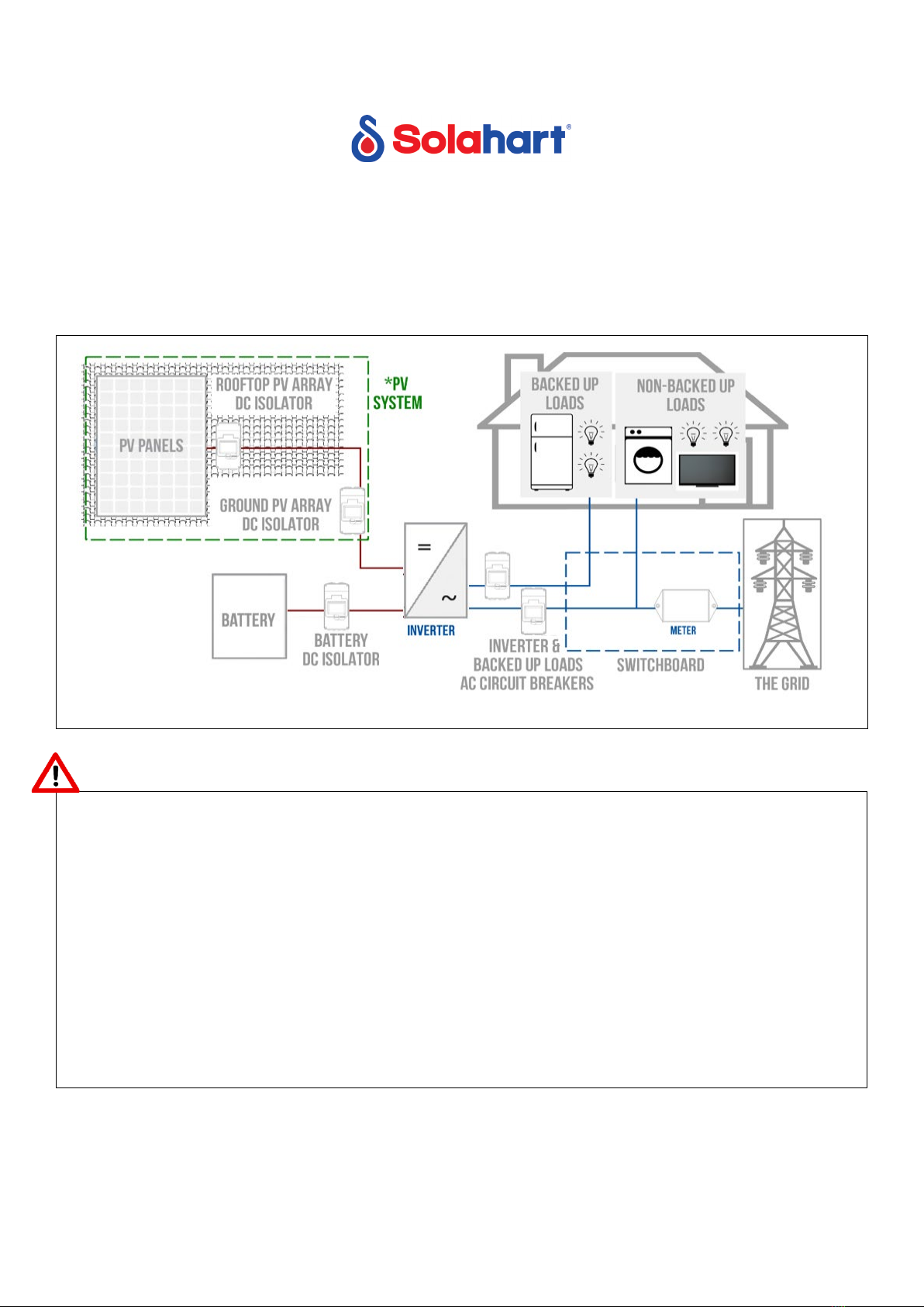
System Overview Diagram
Note:Installation of the PV system is not within the scope of this document.
Warnings
Disclaimer of Liability and Warranty:This pictorial guide does not replace installation manuals supplied
with the components.
Solahart assumes no responsibility for loss, damage or expense resulting from
improper installation, handling, or misuse of components. Refer to the warranty statement in the Solahart
Owner’s guide for full warranty terms and conditions.
The Australian Consumer Law: Our goods come with guarantees that cannot be excluded under the
Australian Consumer Law. You are entitled to a replacement or refund for a major failure and compensation
for any other reasonably foreseeable loss or damage. You are also entitled to have the goods repaired or
replaced if the goods fail to be of acceptable quality and the failure does not amount to a major failure.
Installer Responsibilities
The installer is solely responsible for:
•Observing and conf
orming to all relevant Australian Standards, all relevant Clean Energy Council
Accreditation guidelines and all applicable laws, ordinances, regulations, codes of practice and local
or national building codes, including any that may have superseded this guide.

2
•Ensuring that the installation complies with AS/NZS 3000, AS/NZS 5139, AS/NZS 5033, AS 4777.1,
AS/NZS 1768, AS 3008
and any relevant electrical service and installation rules for the state or
territory where the system is installed.
•Ensuring that the
Battery system and associated components are appropriate for the particular
installation and the installation environment.
•
Ensuring only parts supplied by Solahart Industries and installer supplied parts as specified by
Solahart Industries are utilised (substitution of parts may void the warranty and invalidate certification).
•Ensuring that mounting fasteners have adequate pull-
out strength and shear capacities to suit the
installation.
•Ensuring safe installation of all electrical aspects of the Battery system.
•Ensuring that the building and building structures are capable of withstanding the additional loads and
forces generated as a result of installing the Battery system.
•Ensuring mounting clearance requirements for all components are maintained.
•Ensuring components are not exposed to direct sunlight, rain fall and snow accumulation.
•Ensuring that the batteries and their components are protected from damage during transportation
and storage.
•Ensuring that the weight of the battery is taken into account when handling and that all WHS policies
are followed.
Tools Required
Use insulating tools and wear personal protective equipment (PPE) when operating the equipment to
ensure personal safety. Wear anti-static gloves, cloths, and wrist strips when touching electron devices to
protect the equipment from damage.
•Drill and drill bits suitable for drilling holes in the desired mounting surface/structure.
•M5, M6 & M10 tools.
•Torque wrench.
•Spirit level.
•Adjustable spanner.
•Electricians hand tools (screwdrivers, pliers, side cutters, cable crimps etc.)
•An Android or IOS smart device.
Note: The GoodWe mobile App “PV Master” must be downloaded before commissioning.
Note: See each component installation guides for additional tools required for installation.
3
Planning the Installation
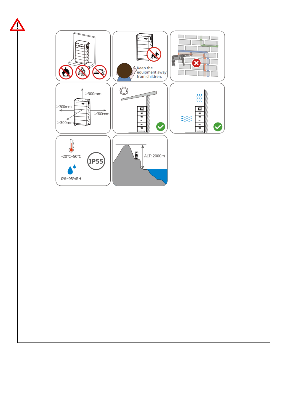
Installation environment
• The battery is floor/wall mounted as per the instructions provided in this guide.
• The operating temperature (charge / discharge) for the battery is -0
℃
~50
℃/
-20
℃
~50
℃.
• Avoid exposing the equipment to direct sunlight or rain.
• Install the equipment away from heat/cold source where the temperature can vary significantly.
• Install the equipment away from strong interference to ensure its reliable operation.
• Keep children / pets away from the equipment.
• Do not install the equipment in places prone to accumulate water.
• Do not put inflammable or explosive materials near the equipment.
4
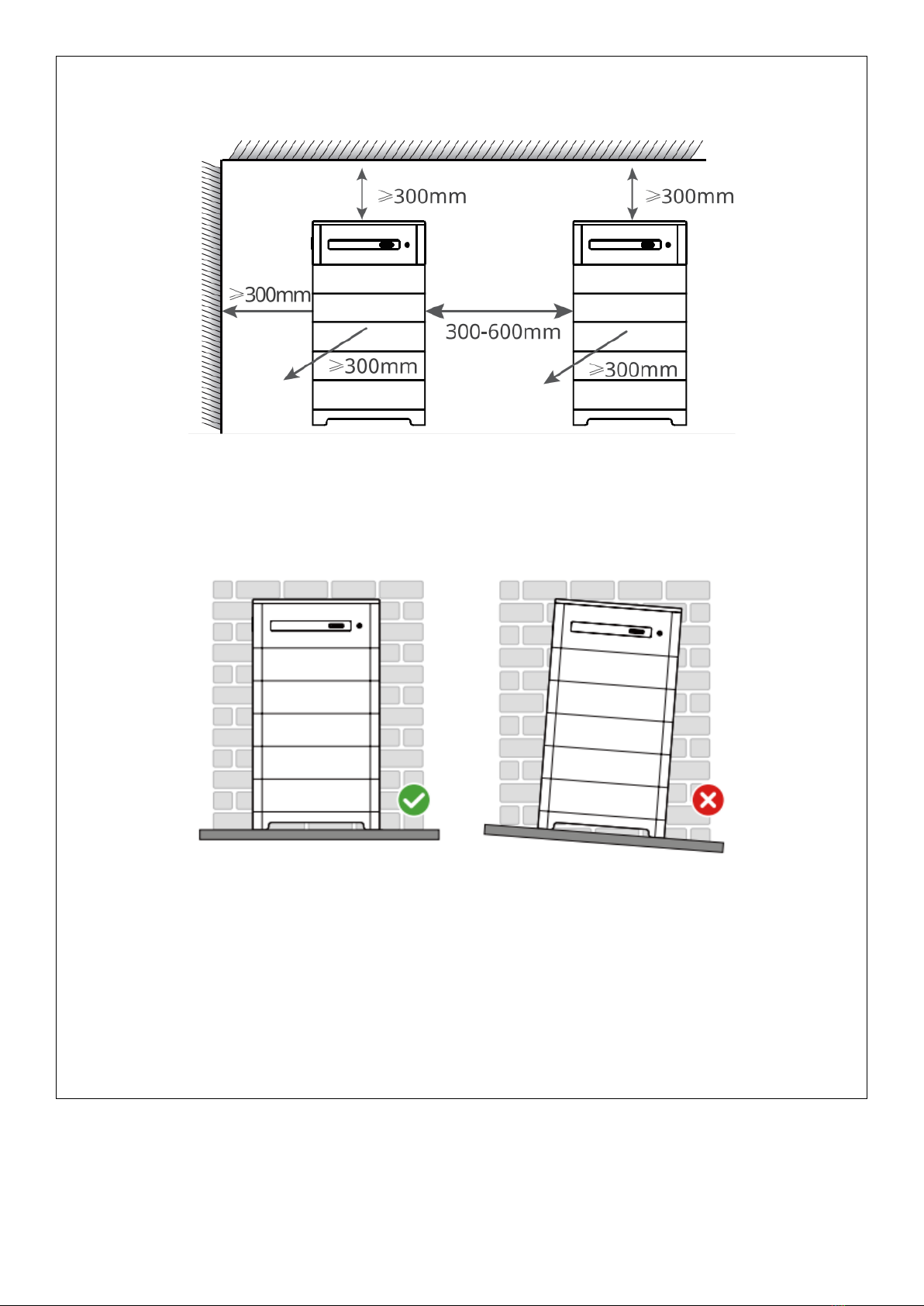
Mounting space requirements for the GoodWe Lynx F Series Battery
Floor mounting space requirements:
Angle requirements:
Note: Battery mounting and installation must comply with Australian standards.
Note: The Installation location of the Battery must also comply with the requirements of AS/NZS 5139.
Note: Refer to the relevant inverter guide for inverter spacing requirements.
5
Cabling and Conduits
Note: Each kit contains connectors/terminal lugs.
Any earthing cable, AC cable and conduits are not supplied by Solahart and should be selected based on
the following criteria.
Inverter DC/AC cabling must be sized and installed in accordance with AS/NZS 3000, AS/NZS 3008.1.1
and any local applicable codes.
DC CABLING
Cable description Cable type Conductor Size
Low Voltage (HV) Battery to Battery
DC Circuit Breaker/Isolator Pair, double insulated single core cables 3-4 mm2
HV Battery DC Circuit
Breaker/Isolator to Inverter Pair, double insulated single core cables
4-6 mm2 (ET Inverter)
12-13 mm2 (GEH Inverter)
6-10 mm2 (EH Inverter)
Battery earthing (PE) Earthing cable complying with requirements of
AS/NZS 3000 10 mm2
Note: Where only one battery tower connected is to the inverter, each DC cable must be installed in
accordance with AS/NZS 3008.1.1 to achieve a current carrying capacity of >25A (in-built rating of
battery circuit breaker). External 32A DC circuit breaker must be installed between the battery
towers and inverter.
Where more than one battery tower is connected, refer to the table below. Some inverters are capable of
max continuous current of 50A. DC cable must achieve a current capacity of >50A for these inverters
(external 63A DC circuit breaker must be installed between the battery towers and inverter).
DC CABLING
Cables must be selected so that the current carrying capacity is suitable for the maximum continuous
current as shown below:
Inverter Model ET Series GEH Series EH
Series
GW5KL-
ET
GW10KL-
ET
GW15KL-
ET
GW20KL-
ET
GW25K
-ET
GW29.9K
-ET
GEH8.6
-1U-10
GEH10
-1U-10
GW500
0-EH
Max.
Continuous
Charging
Current (A)
25 A 25 A 50 A 50 A 50 A x 2
(2
inputs)
50 A x 2
(2 inputs)
50 A 50 A 25 A
Max.
Continuous
Discharging
Current (A)
25 A 25 A 50 A 50 A 50 A x 2
(2
inputs)
50 A x 2
(2 inputs)
50 A 50 A 25 A

6
Refer to the following table for circuit breaker sizing between battery and inverter:
1 Battery Tower 2
Battery
Towers
3
Battery
Towers
4
Battery
Towers
5
Battery
Towers
6
Battery
Towers
7
Battery
Towers
8
Battery
Towers
Number
of
batteries
2 3 4 5 10 15 20 25 30 35 40
3 Phase Hybrid
GW5kL-
ET
32 A 32 A 32 A 32 A 32 A 32 A 32 A 32 A 32 A 32 A 32 A
GW10KL-
ET
32 A 32 A 32 A 32 A 32 A 32 A 32 A 32 A 32 A 32 A 32 A
GW15K-
ET
32 A 32 A 32 A 32 A 63 A 63 A 63 A 63 A 63 A 63 A 63 A
GW20K-
ET
32 A 32 A 32 A 32 A 63 A 63 A 63 A 63 A 63 A 63 A 63 A
GW25K-
ET (per
DC input)
32 A 32 A 32 A 32 A 63 A 63 A 63 A 63 A 63 A 63 A 63 A
GW29.9K
-ET (per
DC input)
32 A 32 A 32 A 32 A 63 A 63 A 63 A 63 A 63 A 63 A 63 A
1 Phase Hybrid
GEH8.6-
1U-10
32 A 32 A 32 A 63 A 63 A 63 A 63 A 63 A 63 A 63 A
GEH10-
1U-10
32 A 32 A 32 A 63 A 63 A 63 A 63 A 63 A 63 A 63 A
GW5000-
EH
32 A 32 A 32 A 32 A 32 A 32 A 32 A 32 A 32 A 32 A 32 A
Note: Maximum batteries per tower for GE inverters is 4. Please note battery tower stacks are in series so
multiple stacks need to be the same size. E.g if one tower stack was 4 , the next tower needs to be 4.
AC CABLING
Cables must be selected so that the current carrying capacity is suitable for the maximum continuous
current as shown below:
ET Series GEH Series EH
Series
Inverter Model GW5KL-
ET
GW10KL-
ET
GW15KL-
ET
GW20KL-
ET
GW25K
-ET
GW29.9K
-ET
GEH8.6
-1U-10
GEH10
-1U-10
GW500
0-EH
Max AC
Current (On
Grid) -
incoming
15.2 A
22.7 A
34.0 A
45.0 A
50.0 A
50.0 A
45.5 A
45.5 A
43.4A
Max AC
Current
(Backup,
continuous)
8.5 A
16.5 A
22.7 A
30.3 A
37.9 A
45.5 A
39 A
43.5 A
21.7A
7
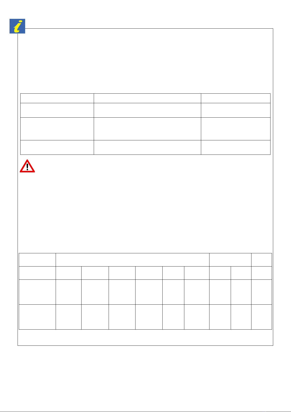
COMMUNICATION CABLING
Communication cables are provided and pre-fitted on GoodWe Inverters. Extension of communication
cable is permitted to the maximum length specified in the table below.
Cable Description Cable Type Provided Cable
Length Maximum Length
Cable between Inverter and
Smart Meter
Data cable with RJ 45 connector pre-
crimped on Meter end 10 m 100 m
Cable between Smart Meter and
CT Data cable with 1 twisted pair 3 m 5 m
Cable between Inverter and
Battery
Data cable with RJ 45 connector pre-
crimped on Battery end 3 m 100 m
Note: Check insulation voltage rating of these communication cables.
NOTE: ADDITIONAL CONDUIT TERMINATORS/GLANDS MAY BE REQUIRED DEPENDING ON THE
INSTALLATION LOCATION.
Note: Refer to AS/NZS 3000 for appropriate conduit sizing.
Unpacking and Mounting Battery
Refer to GoodWe Lynx F-Series User Manual for further mounting instructions.
1
8
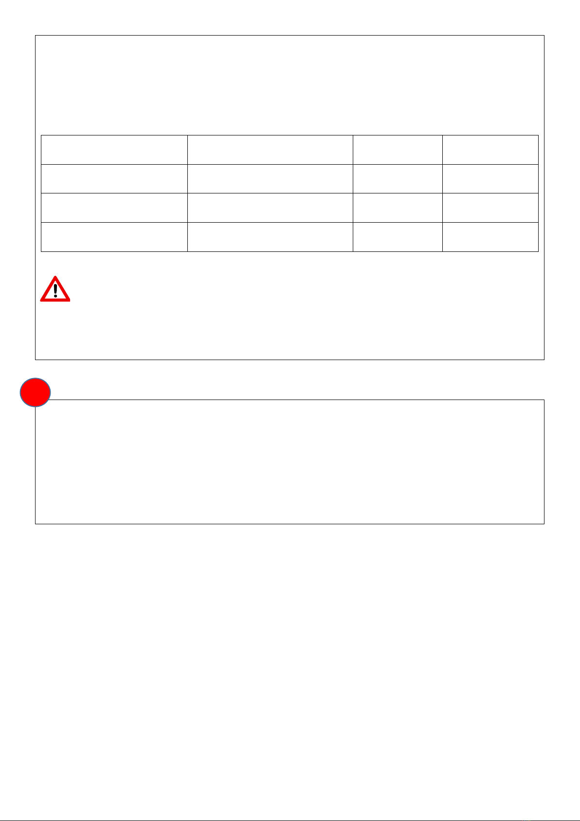
Unpack contents from the GoodWe battery packaging.
Warning: Battery modules are heavy (approximately 45 kg each). It is recommended that the
installation is done by two people.
Note: If multiple batteries are to be connected, check that the production date is similar and cell grade is
the same.

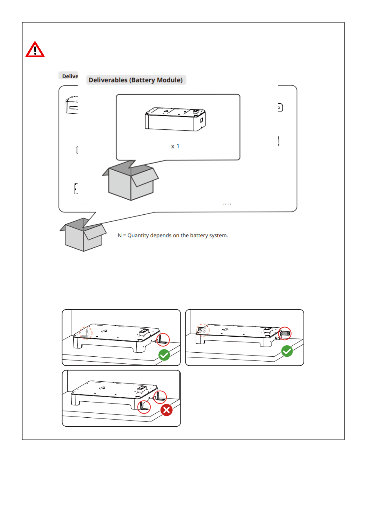
9
• Ensure that the base stands on the floor vertically.
• Ensure that the base clings to the wall and the arrow points outward.
• Ensure that all batteries cling to the wall and the arrow points outward.
• Align the holes of the upper and the lower battery modules when placing the upper battery module.
• Ensure that the locking bracket clings to the wall.
• Do not install the two locking brackets on one side
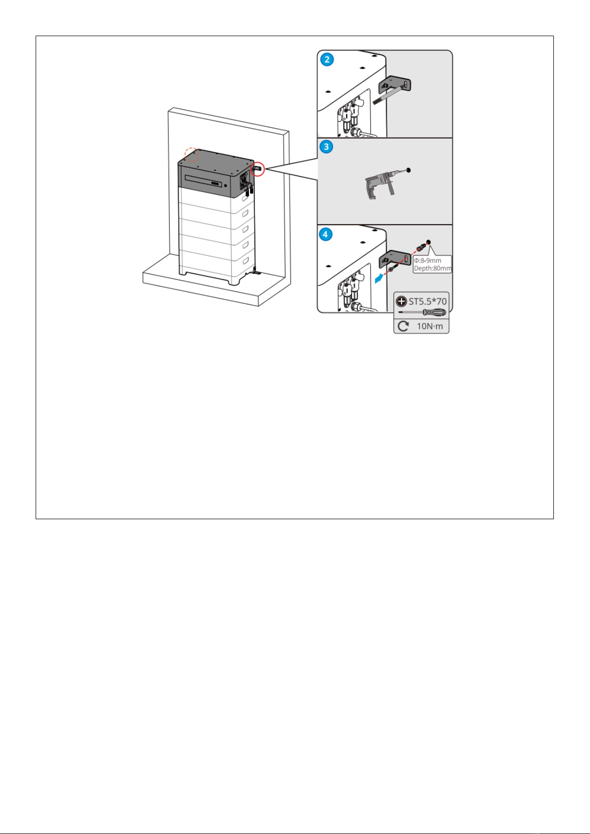
Battery System Installation(Without adjustable leveling feet)
Floor mounting:
1. Make sure that the floor is flat and horizontal. Install the anti-dumping bracket on both sides.
2. Align the battery and the wall, then put the anti-dumping bracket close to the wall. Mark the drilling
position and remove the battery.
3. Drill a hole on the wall using the power drill. The hole diameter shall be 10mm at a depth of 80mm.
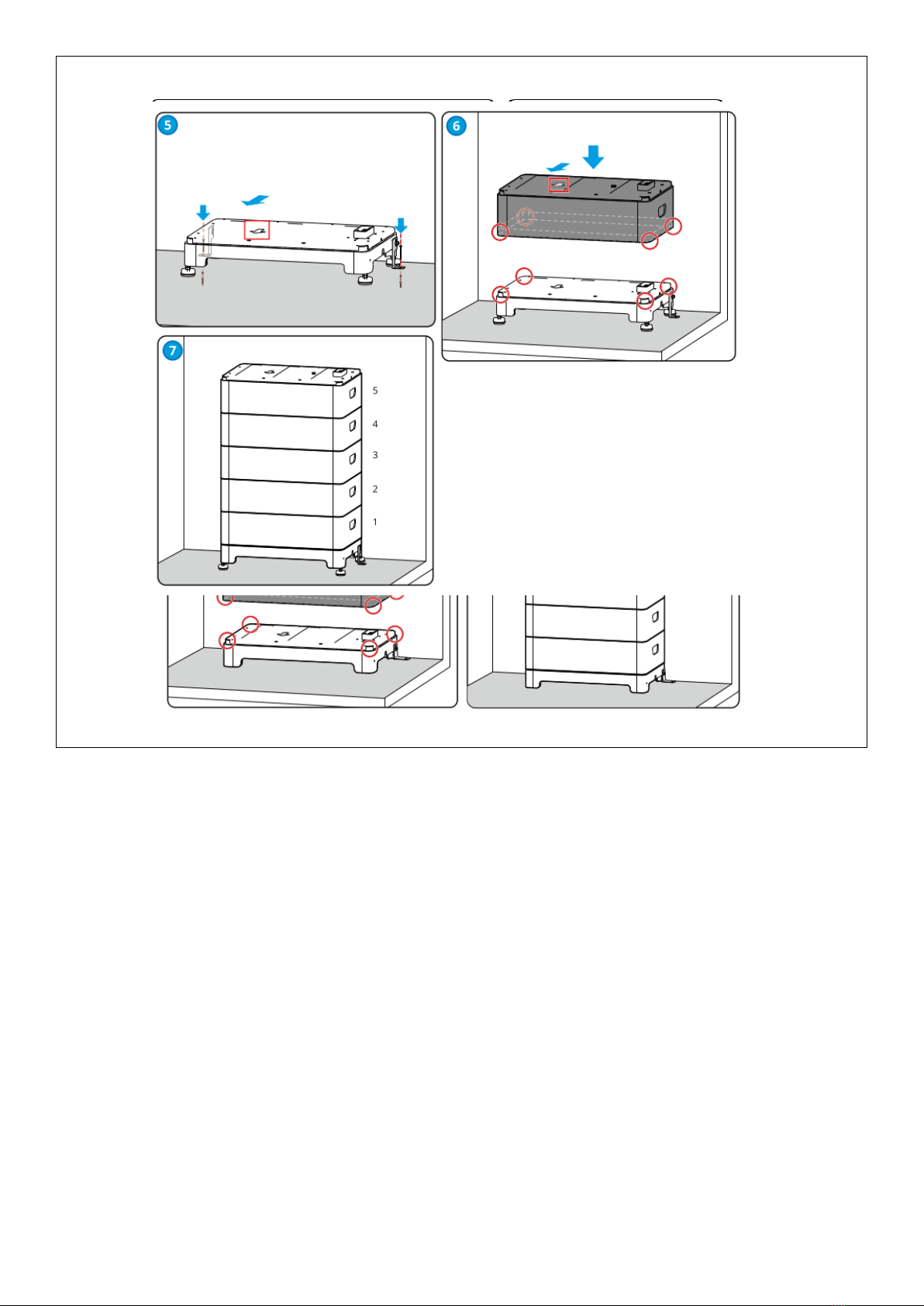
10
4. Fix the expansion bolts, tightening torque: 4N·m.
11
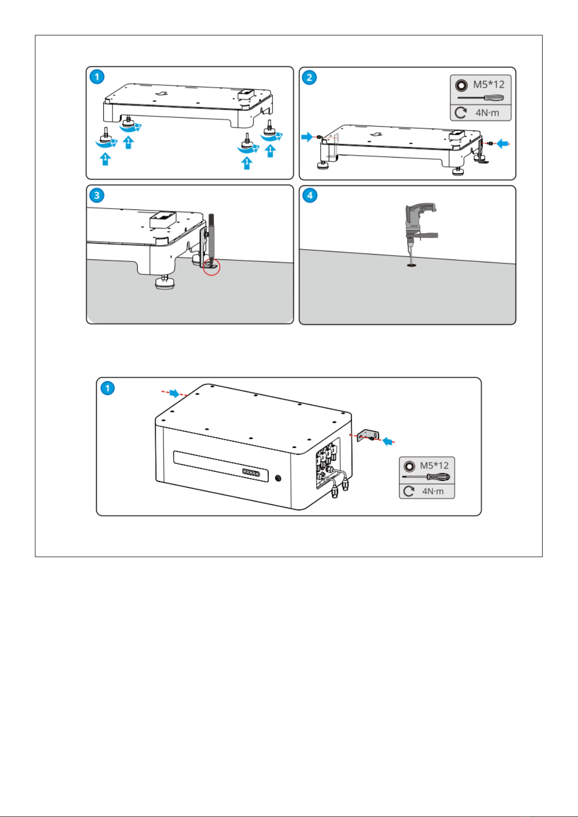
Battery System Installation(With adjustable leveling feet)
Installation of PCU
12
Connecting Terminal resistor
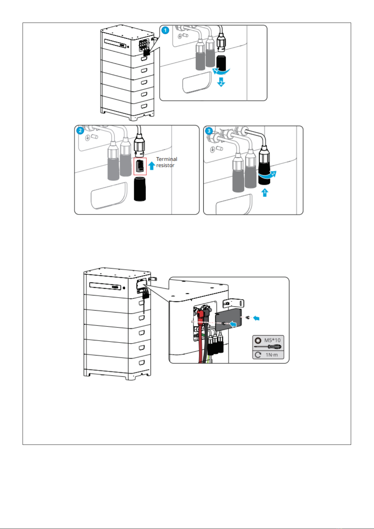
13
Installing the protection cover
Note: The battery shall be installed and mechanically protected according to CEC
Battery Installation
Guidelines and AS/NZS 5139. This includes:
14
•
Providing restricted access to the battery system designed to prevent access by unauthorised
persons.
•Where subject to potential physical damage, mechanical protection shall be provided to the battery
system to minimise the risk of such, resulting in electrolyte leakage, including:
oCrushing
oImpact
oPuncturing
•Mechanical protection may be achieved via the use of a suitable battery system enclosure and/ or
bollards.
Mounting the Inverter
Follow the GoodWe ET, GEH, EH Series User Manuals to choose a suitable location and correctly mount
the Inverter to the wall using appropriate fasteners and with regards to clearance requirements.
A lock can be installed on the inverter for anti-theft purposes.
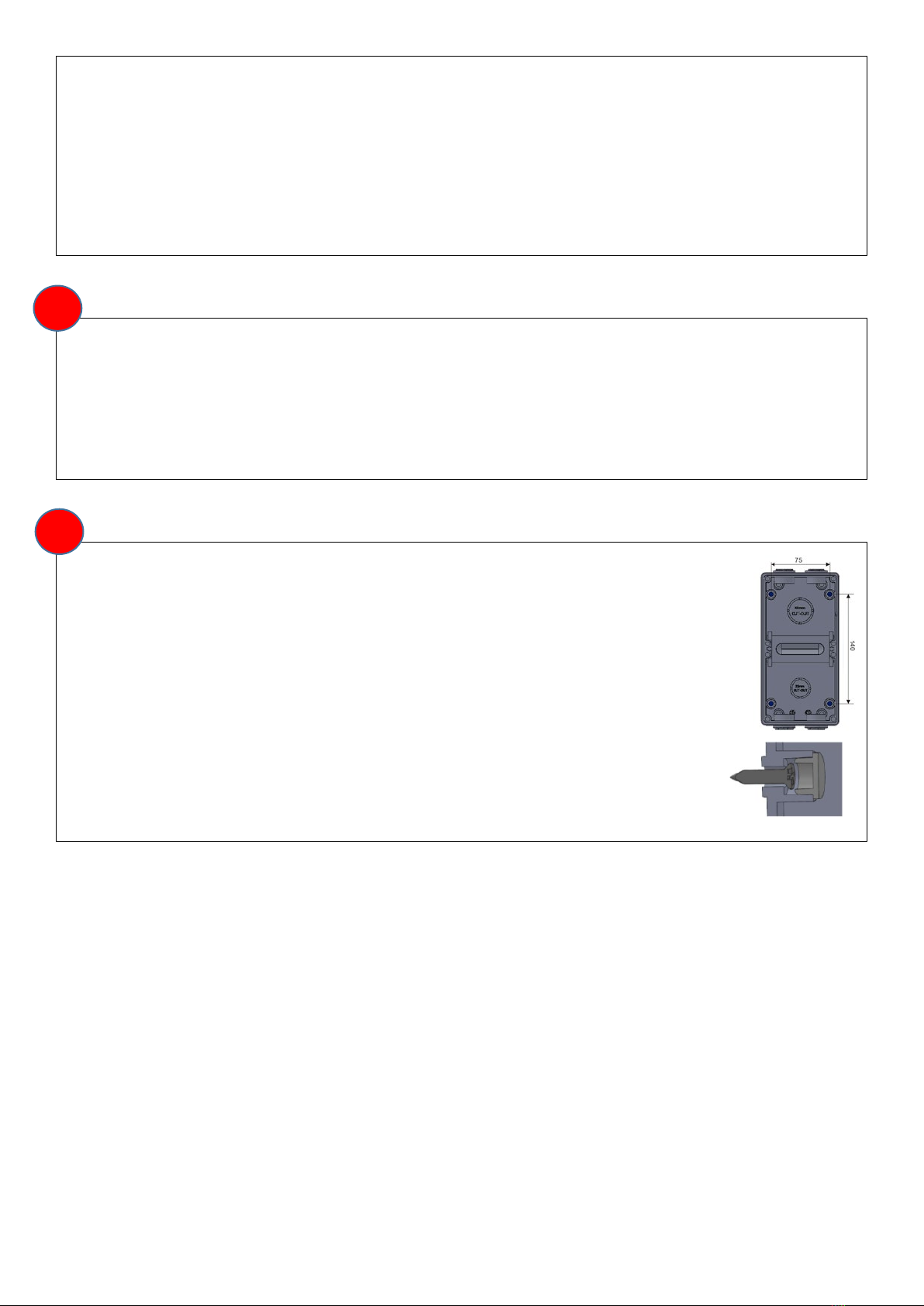
Mounting AC Isolator Enclosure(s)
ISOLATOR ENCLOSURES
1. Determine the mounting locations of the enclosures with regard to system clearances,
layout specifications and AS/NZS 3000.
2. Install a minimum of two (2) fasteners diagonally opposite, to fix the enclosure to the
wall.
3. Install the silicone rubber plugs supplied with the enclosure on the internal mounting
points.
Note: Where the Inverter is not adjacent to the switchboard to which it is connected,
an “Inverter AC Isolator” must be installed at the Inverter in accordance with
AS/NZS 3000.
3
2
15
Mounting Smart Meter
The Smart Meter can be attached to a DIN rail inside the switchboard via mounting clips supplied with the
Meter.
Note: Check Smart Meter and CT communication cable to ensure insulation is rated for the highest voltage
present inside the switchboard. Additional insulation may be required.
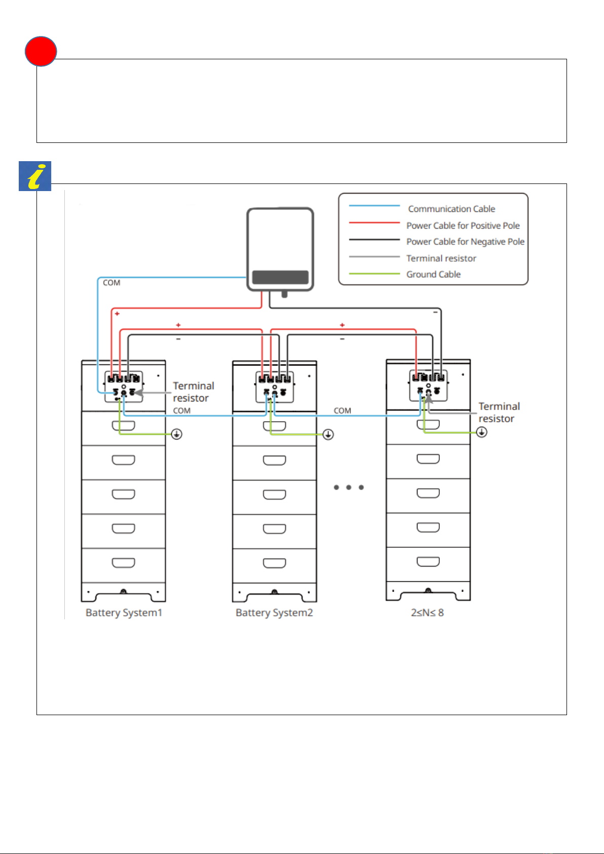
Battery - Inverter Wiring Diagrams
4
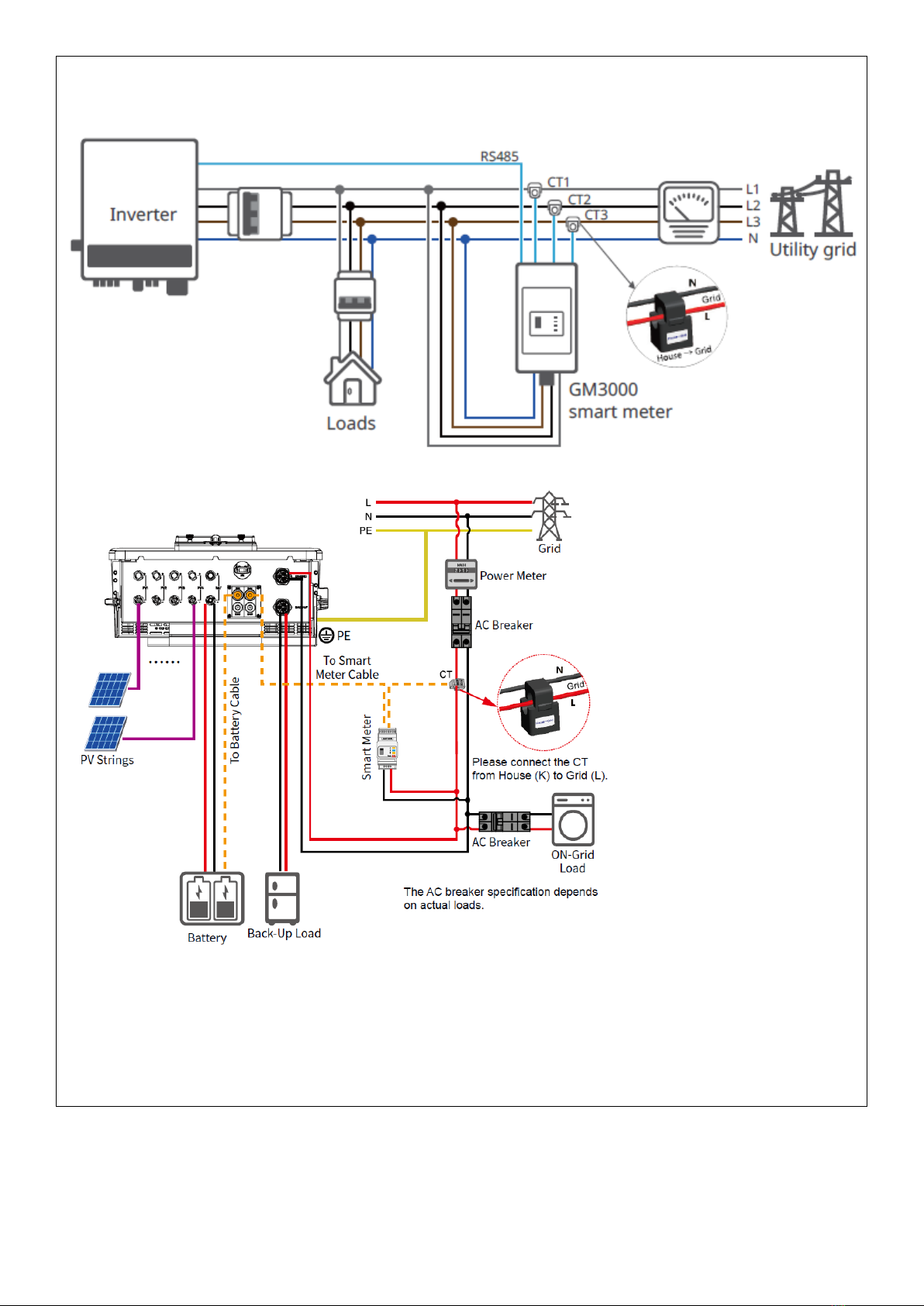
16
ET Series Inverters
Refer to the relevant ET Series Inverter manual for further information,
GEH Series Inverters
17
EH Series Inverters
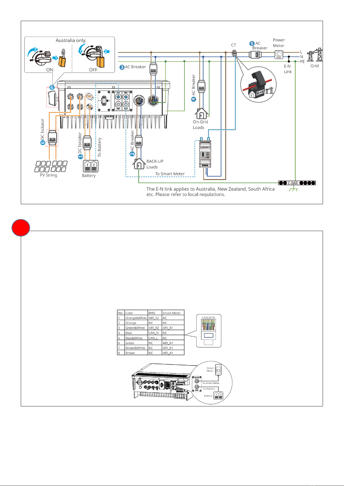
Communication Cable Wiring
INVERTER
Communication cables to the Battery (CAN COM) and the Smart Meter (RS-485) are pre-installed at the
inverter. Check all connections prior to installation.
All communication cabling between inverter, battery and metering shall be mechanically protected to
prevent damage from vermin and tampering from unauthorised users.
ET Series
5
18
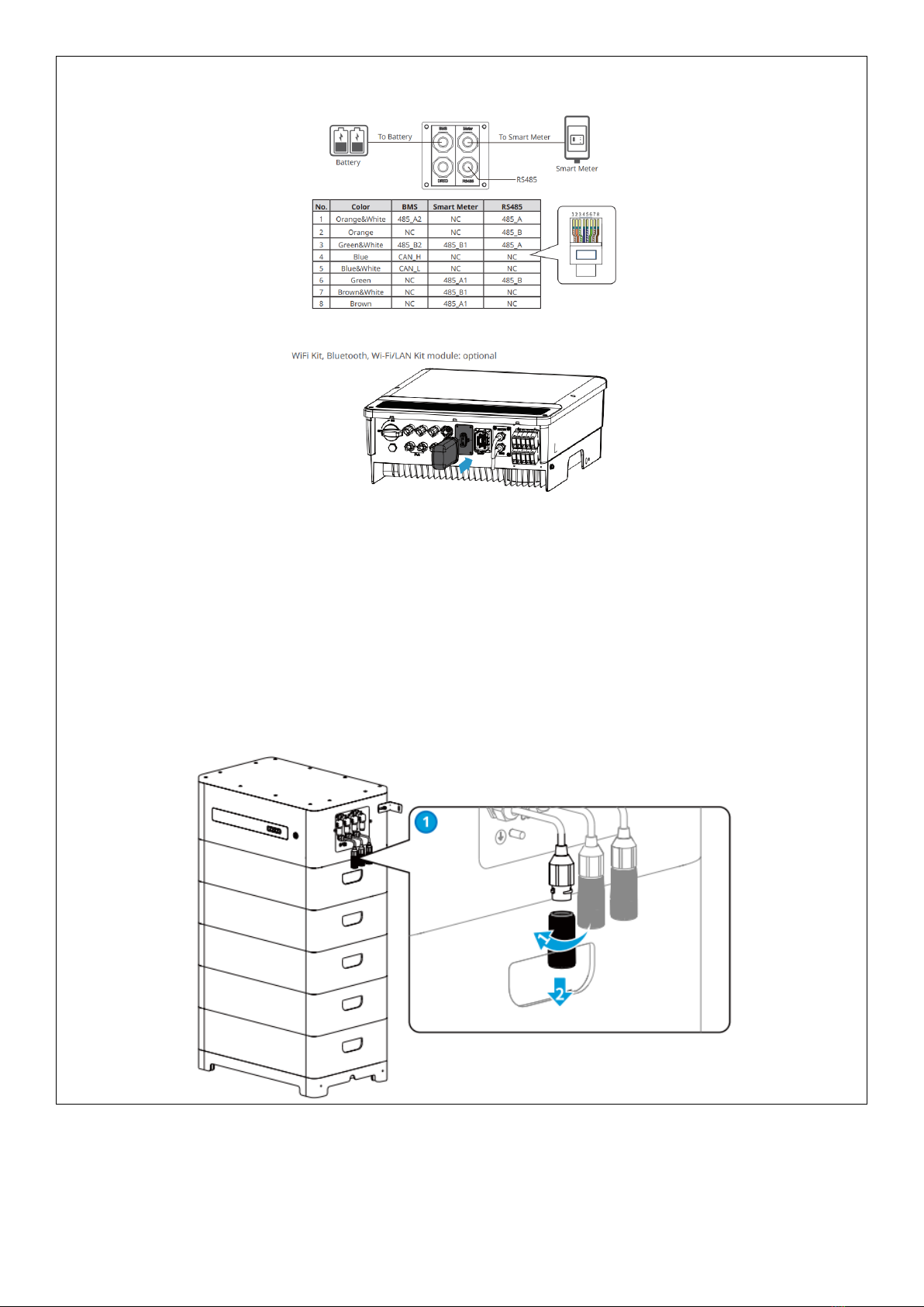
GEH and EH Series
BATTERY
Connecting the Communication Cable
•Do not use RJ45 cable with protective cover.
•When one battery is applied, connect one communication cable to the inverter by RJ45 connector
and connect the other cable to the terminal resistance.
•When multiple batteries are applied, connect the communication ports in series using net cables.
Connect one communication cable of the last battery to the terminal resistance.
1. Remove the waterproof module.
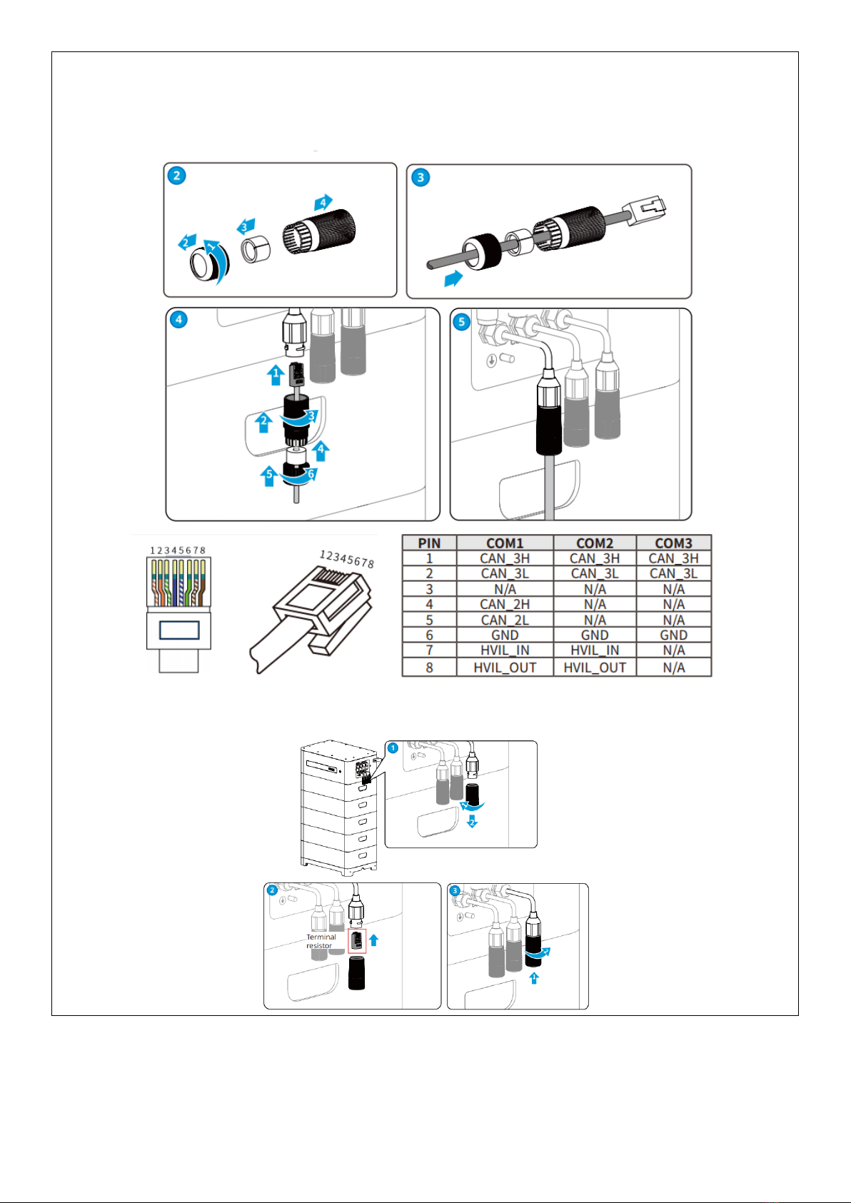
19
2. Route the cable through the waterproof module.
3. Crimp the RJ45 Registered Jack.
4. Secure the back cover.
5. Connect the communication cable and the terminal resistance to the battery.

20
6. Secure the cover.
METER
Follow instructions from GoodWe ET, EH and GEH User Manual to connect the communication cable from
the Inverter.
Note: Check the communication cables to ensure the insulation is rated for the highest voltage present
inside the switchboard. Additional insulation may be required.
Note: If extension of communication cable is required, a female RJ45 joiner may be used to avoid crimping
the connector.
Warning: If extension of communication cable is required, ensure cable joints are adequately
protected from moisture.
Warning: Ensure all communication cables are adequately protected against mechanical
damage.
DC and AC Cable Wiring
Refer to the wiring diagrams on page 12.
Warning: Ensure all DC and AC cables are adequately protected against vermin and other
damage.
Warning: Ensure in-built DC isolator is switched OFF prior to wiring.
Note: Ensure the conductors on all cable ends are consolidated (e.g. using bootlace) before termination.
BATTERY
Connect DC cable and earthing wire according to the instructions in GoodWe Lynx F-Series Operating
Manual.
6
This manual suits for next models
12
Table of contents


