3
Avvertenze generali
L’installazione del presente kit deve essere eettuata in ottemperanza alle norme
vigenti, secondo le istruzioni del costruttore e da personale professionalmente
abilitato, intendendo per tale quello avente specica competenza tecnica nel
settore degli impianti, come previsto dalla Legge. Questo dispositivo dovrà essere
destinato solo all’uso per il quale è stato espressamente previsto. Ogni altro uso è
da considerarsi improprio e quindi pericoloso.
In caso di errori nell’installazione, nell’esercizio o nella manutenzione, dovuti
all’inosservanza della legislazione tecnica vigente, della normativa o delle istru-
zioni contenute nel presente libretto (o comunque fornite dal costruttore), viene
esclusa qualsiasi responsabilità contrattuale ed extracontrattuale del costruttore
per eventuali danni e decade la garanzia relativa all’apparecchio.
Premessa: il presente libretto di istruzioni contiene esclusivamente informazioni
tecniche relative all’installazione del kit Immergas e non entra nel merito di
altre tematiche correlate all’installazione del kit stesso (a titolo esemplicativo
sicurezza sui luoghi di lavoro, ecc.).
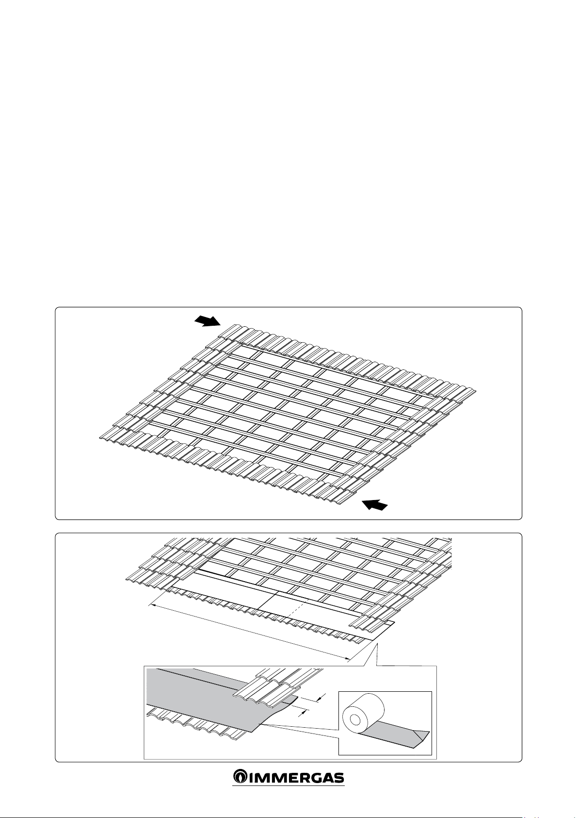
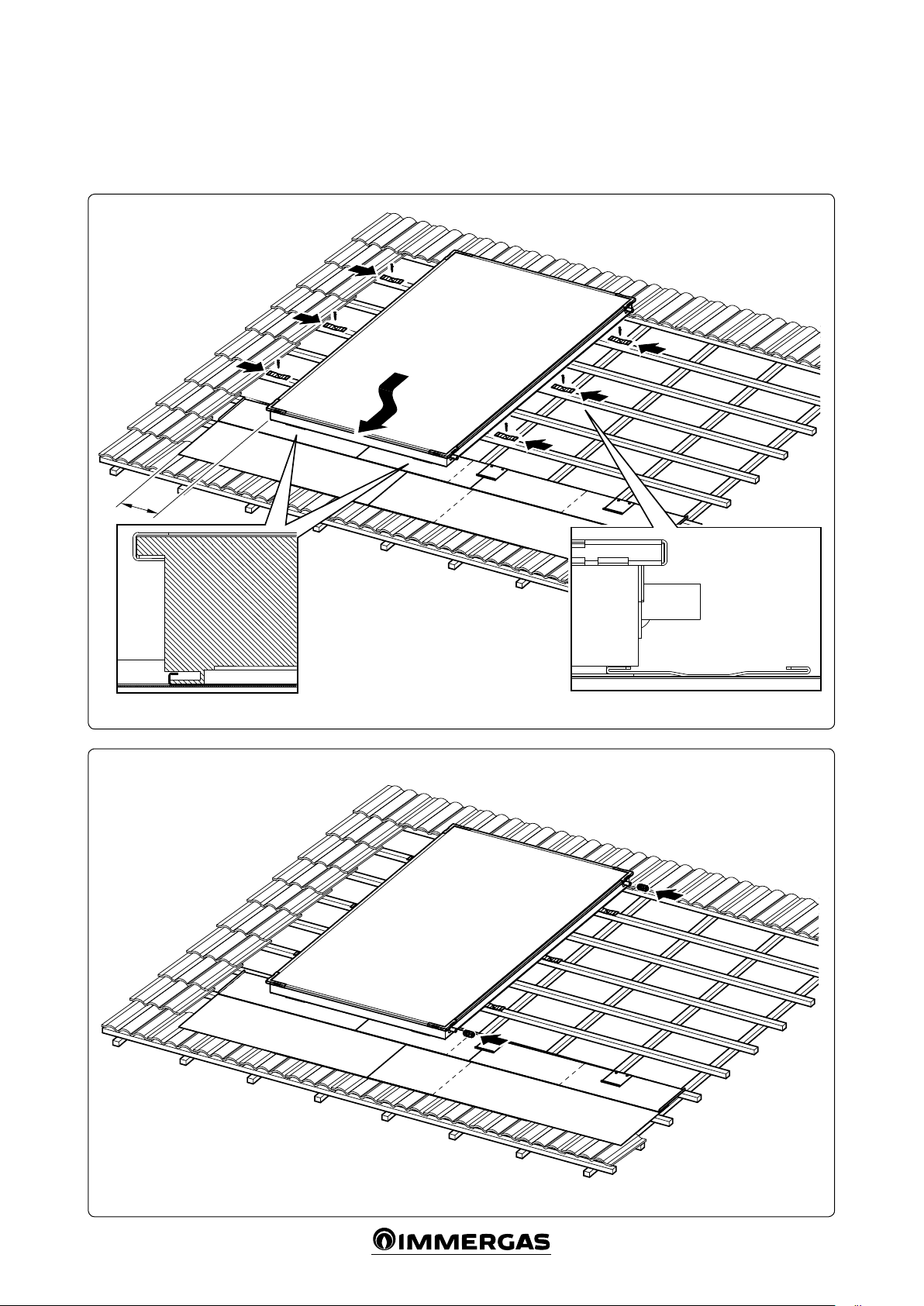
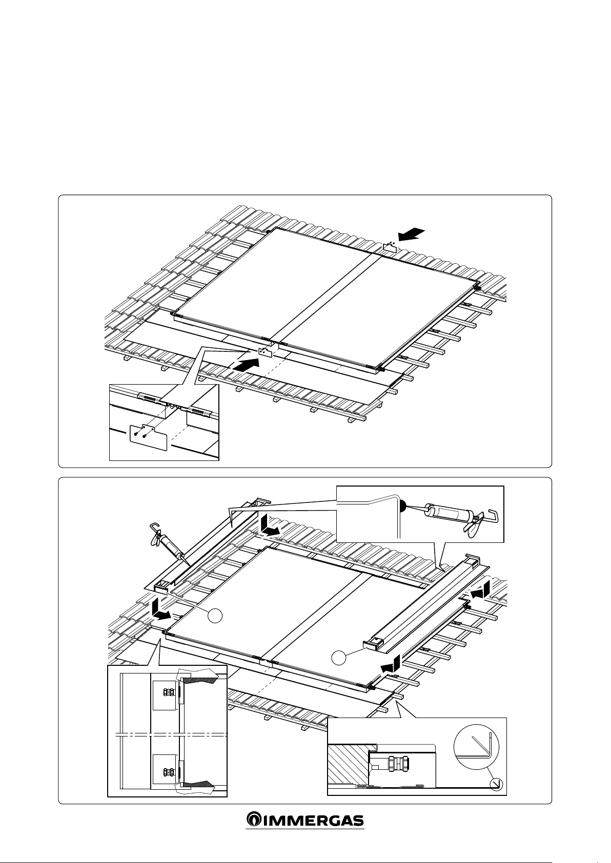
DESCRIZIONE.
La struttura descritta di seguito permette l’installazione dei collettori solari
incassati nel tetto.
Questo sistema ad incasso isola il pannello solare sul tetto, pertanto non vi
è necessità di ulteriori sigillature / adattamenti, in quanto il deusso delle
intemperie avviene sopra il pannello stesso.
COMPOSIZIONE DEL KIT INCASSO
Descrizione Qtà
Rotolo
1
Base di sostegno
1
Tappeto isolante
2
Striscia isolante
6
Vite per legno 5x70
2
Vite 4x35
26
Cartuccia silicone
1
Viti AF 4,2x13
16
Scolo inferiore SX
1
Scolo inferiore DX
1
Squadretta posizionamento collettore
2
Staa ssaggio collettore
6
Squadretta ssaggio carter laterale
8
Squadretta chiusura ispezione
4
Gruppo angolare SX
1
Gruppo angolare DX
1
Gruppo carter laterale SX
1
Gruppo carter laterale DX
1
COMPOSIZIONE DEL KIT ESTENSIONE PER KIT INCASSO
Descrizione Qtà
Rotolo
1
Base di sostegno
1
Vite per legno 5x70
2
Vite 4x35
12
Viti AF 4,2x13
4
Scolo
1
Squadretta posizionamento collettore
2
Staa ssaggio collettore
3
Carter mediano
1
Carter superiore
1
Chiusura carter mediano
2
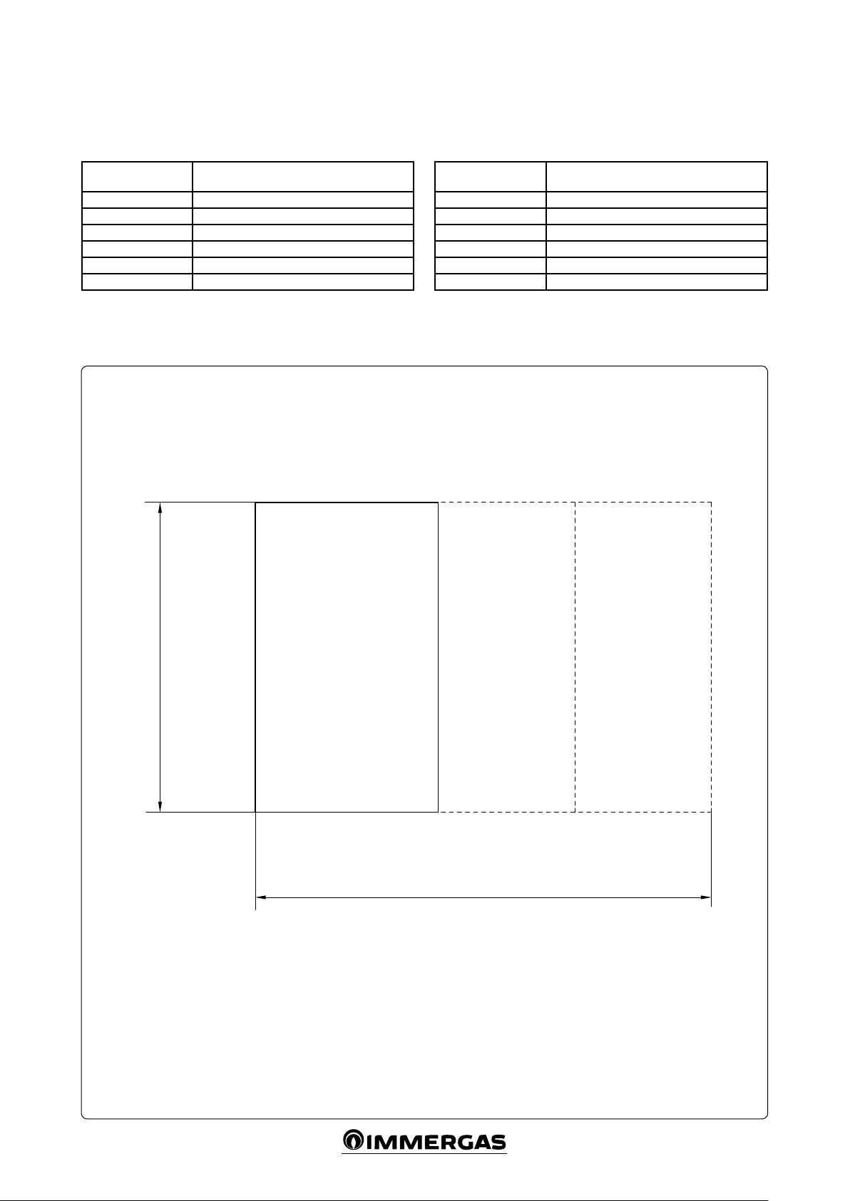
INSTALLAZIONE VERTICALE
IT
General recommendations
is kit must be installed in compliance with the regulations in force, according
to the instructions of the manufacturer and by professionally qualied personnel,
having specic technical skills in the plant sector. e appliance must only be
used for that, expressly foreseen. Any other use must be considered improper and
therefore dangerous.
If errors occur during installation, operation and maintenance, due to non
compliance with the technical laws in force, standards or instructions contained
in this manual (or however supplied by the manufacturer), the manufacturer
accepts no contractual and extra-contractual liability for any damages and the
appliance warranty is invalidated.
Foreword: this instruction booklet contains only technical information to install
the Immergas kit and does not involve other issues linked to the kit installation
(e.g. safety in workplaces, etc.).
DESCRIPTION.
The structure described below allows roof installation of recessed solar
manifolds.
is recessed system isolates the solar panel on the roof, therefore no ad-
ditional sealing / adjustments are required as the bad weather outows above
the panel itself.
COMPOSITION OF THE RECESSED KIT
Description Qty
Roll
1
Support base
1
Insulating mat
2
Insulating strip
6
5x70 wood screw
2
4x35 screw
26
Silicone cartridge
1
4.2x13 self-tapping screws
16
Bottom le drain
1
Bottom right drain
1
Manifold positioning bracket
2
Manifold xing bracket
6
Side guard xing bracket
8
Inspection closure bracket
Le corner group
1
Right corner group
1
Le side guard group
1
Right side guard group
1
COMPOSITION OF EXTENSION KIT FOR RECESSED KIT
Description Qty
Roll
1
Support base
1
5x70 wood screw
2
4x35 screw
12
4.2x13 self-tapping screws
4
Drain
1
Manifold positioning bracket
2
Manifold xing bracket
3
Middle guard
1
Top guard
1
Middle guard closure
2
VERTICAL INSTALLATION
IE