manuals.online logo
Brands
  1. Home
  2. •
  3. Brands
  4. •
  5. aptos
  6. •
  7. Solar Panel
  8. •
  9. aptos DNA-120 Series User manual

aptos DNA-120 Series User manual

This manual suits for next models

13

Other aptos Solar Panel manuals

aptos DNA-144-MF26-440W User manual

aptos

aptos DNA-144-MF26-440W User manual

aptos DNA-108 Series User manual

aptos

aptos DNA-108 Series User manual

Popular Solar Panel manuals by other brands

O.N 23.8757.15 user manual

O.N

O.N 23.8757.15 user manual

PV-ezRack DFendr installation guide

PV-ezRack

PV-ezRack DFendr installation guide

Navitron HFC-2 installation instructions

Navitron

Navitron HFC-2 installation instructions

AXITEC 60-CELL installation manual

AXITEC

AXITEC 60-CELL installation manual

thermital TSOL 20 N BLU installation instructions

thermital

thermital TSOL 20 N BLU installation instructions

moovo KSM001 Installation and use instructions and warnings

moovo

moovo KSM001 Installation and use instructions and warnings

AZO Digital MPPT-3000 operating manual

AZO Digital

AZO Digital MPPT-3000 operating manual

Clenergy PV-ezRack SolarTripod installation guide

Clenergy

Clenergy PV-ezRack SolarTripod installation guide

Beretta SCF-20N installation manual

Beretta

Beretta SCF-20N installation manual

Solarland Portable Series Instruction handbook

Solarland

Solarland Portable Series Instruction handbook

Ubiquiti sunMAX user guide

Ubiquiti

Ubiquiti sunMAX user guide

Sonnenkraft GK5-HP manual

Sonnenkraft

Sonnenkraft GK5-HP manual

REC TwinPeak 2S Mono 72 Series installation instructions

REC

REC TwinPeak 2S Mono 72 Series installation instructions

Flexsolar C100 Instruction manual & warranty

Flexsolar

Flexsolar C100 Instruction manual & warranty

Energizer HardCase Sunpack 120W user guide

Energizer

Energizer HardCase Sunpack 120W user guide

solarwatt EasyIn 60M Series installation instructions

solarwatt

solarwatt EasyIn 60M Series installation instructions

Mission Solar Energy MONO Series Installation and user manual

Mission Solar Energy

Mission Solar Energy MONO Series Installation and user manual

Wiedenmann Favorit XP Translation of original operating instructions

Wiedenmann

Wiedenmann Favorit XP Translation of original operating instructions

manuals.online logo
manuals.online logoBrands
  • About & Mission
  • Contact us
  • Privacy Policy
  • Terms and Conditions

Copyright 2025 Manuals.Online. All Rights Reserved.

InstallationManual
HighEfficiencyHalf-CellModule
Introduction
Thismanualcontainsinformationaboutelectricaland
mechanicalinstallationof thesolarpanels: DNA-120
and DNA-144 Series
Disclaimer of Liability
Installation techniquesand methodsof this product is
beyondAptosSolarTechnology’s control. ASTdoesnot
assumeresponsibilityof lossor damageresulting from
improper installation, handlingor use.ASTdisclaims liability
for damage,loss,expensearising out of, or in anyway
connectedwith installation,useormaintenanceby usingthis
manual
Regulation Information
Thiscertified product meets the UL1703standard for
maximum systemvoltage of 1500Vwith maximum
overcurrentprotection rating of 20A.Theinstaller or system
integratoris assumedtheresponsibilitytoensurecompliance
with all localelectrical codeswhich maybe applicable.
Warnings & Safety
Solarpanels generateelectricitywhen exposedtolight,
which cancauselethal shockand burnhazards.
Onlyauthorized,qualified and trained installers should
handle thesesolarpanels.Do not touchlive terminals with
barehands.Workonly in dryweatherwith dry solarpanels
and tools.
Donot makeconnections while under load. Donot
disconnect under load. Useinsulated tools for electrical
connections.Donotsteporstandon thesolarpanel.Donot
disassemblethesolarpanel orjunctionbox.
Carrypanelwith two or more person. Do not carryby its
wires or junction box.Wear non-slip,suitableglovesand
protectiveclothing.
Donot install the solar panel where flammablevaporsor
gasesarepresent.Do not installin corrosiveenvironment.
Donot direct artificiallyconcentratedsunlighton solarpanel.
Fire Rating
If mounted over aroof, the solarpanel shall bemounted
overafireresistantroofcoveringratedfortheapplication.
Referto local authority for guidelines and regulations for
building fireprotectionand requiredslope.The module
fire performance rating is Type I.
Installing the Panel
AptosSolarTechnologypanels maybe installed invarious
applications.Theparticular mounting isto be defined by
thesystemdesigner.Installermusthandleand mountthe
modules to prevent anyimpact on front surface,back
surface,and framesas thiscouldresultin damage.
Supportstructuresusedto support ASTDNApanelsshould
be wind rated and approvedfor usebythe appropriate
codesprior to installation. In addition, they must be
designedfrommaterialsthatretainstructuralintegrityover
the25 yearslifespanofthepanels theysupport.
ASTDNApanels maybe installed in portraits orlandscape
orientation.
Aminimumoftilt angleof 5degreesis requiredtoensure
drainageand enablerainwater.
Thejunctionbox edgeshouldbe at thetopwhenmounted
in portraitorientation.
Specificrails and frameclips approvedby ASTare listed in
Table1.Alternative rails and frameclips/fastenersneed to
be approvedby ASTto ensurecompliance toUL1703safety
standard.
Framecross-section
Module Wiring
ASTDNApanelsarepre-wired and terminated withMC4-
compatibleconnectors.
Connectionstootherpanelsshouldusecompatible
connectorsthatcomplywith Coderequirements
AST recommendsthatallwiring be doubleinsulatedwith a
minimum rating of 90 C,and wiring should useflexible
copperconductorswhere minimumsizeshouldbe
determined bytheapplicable Codes.
www.aptossolar.com | info@aptossolar.com Page1 All Rights Reserved.DNA-120/144InstallationManual Rev0.0
InstallationManual
HighEfficiencyHalf-CellModule
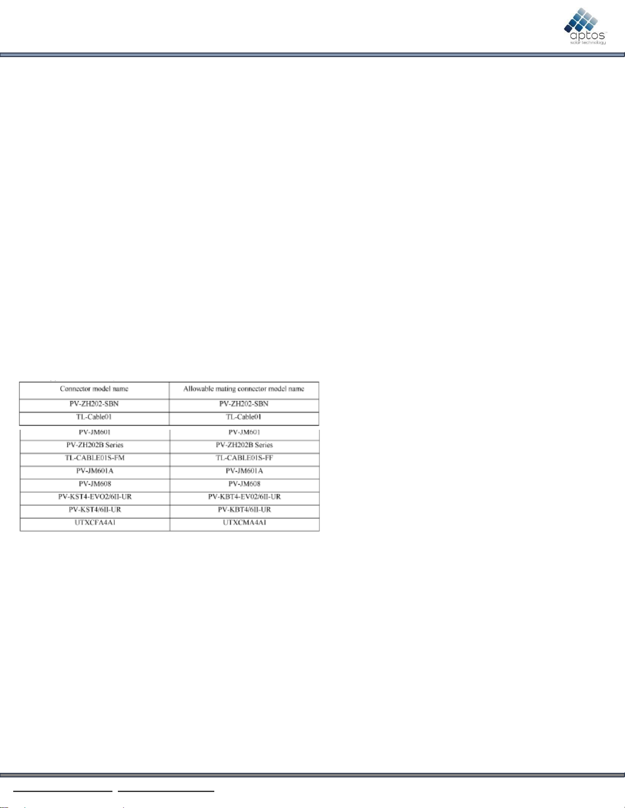
Thecablesand connectorsareUVand weather resistant
from -40 Cto +90C,and rated for1500VDC
Panelsmaybe wired in seriesor parallelto obtain
desiredvoltagesandcurrent,butmustnotexceedthe
systemrating for voltageandcurrent.
ASTpanelsmayproduceup to 20%morepower than
STCrating, dependingon systemdesignandalbedo.
Theadditional power gainshouldbe takeninto
considerationwhendetermining optimum system
sizing,string length, and selectingsystemcomponents
andwiring.
Overcurrentprotectiondevicesshould be employed.
20Acurrent rating for seriesor parallel.Pleasecomply
with all codeand designrequirements.
Grounding
NEC, article 250 governs grounding method.
Grounding method must follow local electric codes.
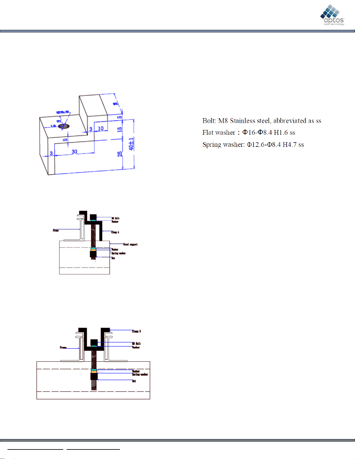
Use bolt, M4, cup washer, grounding wires, flat
washer, tooth washer, screw nut, M4 and install as
shown in the diagram below. Torque specification is 2
to 3 Nm. Grounding materials is evaluated under
UL1703.
Maintenance
ASTDNApanelsare designedto require little to no
maintenance.Dependingon local conditions,panels
mayneedperiodiccleaningto removedirt build-upand
soiling. Panelsshouldbe washedwith water to remove
dirt and soiling. Frequencyof cleaning will dependon
localweather conditionsand paneltilt. Onceayear,
havequalified serviceprofessionalcheckthe general
conditionof wiring and checkto be surethat mounting
hardware isat the correct torque. Looseconnections
mayresult in damagedpanels.
Panelsgenerateelectricity when there issunlight,and
cleaning/maintenancepersonnelmusttakeproper
precautions.
Specifications
Theelectricalcharacteristicsarewithin ±10 %of the
indicatedvaluesof Isc,Imp,Vmp,and Vocand ±3 %of
the indicated valuePmaxunderstandardtesting
conditions(irradiance of 1000/m2,AM1.5spectrum,
and acelltemperature of 25C
Undernormalconditions, solarpanelsislikely to
experienceconditionsthat producemorecurrent
and/orvoltagethanstatedat standardtest conditions.
Accordingly,the valuesof Iscand Voc,inclusiveof
bifacialgain,shouldbe multipliedbyafactorof 1.25,
or more,whendetermining component voltage
ratings, and sizeof controlsconnectedto the PV
output. (Referto codeand designrequirements).
ASTDNApanelshaveamaximumsystemvoltageof
1500VDC.Somegrid-tied systemsoperateor nearthis
voltagerating. TheVocincreasesasthe ambient
temperaturedecreases
Maximumsystemvoltageiscomputedasthe sumof
the open-circuit voltageof the series-connected
panelsforthe lowest expected ambient temperature.
Temperature coefficients can be used to provide the
most accurate prediction of the panel voltage under
temperatureextremes.
www.aptossolar.com | info@aptossolar.com Page2 All Rights Reserved.DNA-120/144 InstallationManual Rev0.0
DNA390–415WInstallationManual
HighEfficiencyBifacialHalf-CellModule
Mechanical Drawings
Installersmustusepre-drilledmountingholeson the
frame.
Frameclip musthaveminimum height dimensionas
shown.
End FrameClip
Mid FrameClip
Mounting Methods
Mountingholesare14mmby9mm.
M8 bolt andfasteners
Torquevalue is12.5Nm–18 Nm
Railscanrunperpendicularor parallelto panellength
(Seefigure 1)
Fasteners
www.aptossolar.com | info@aptossolar.com Page3 All Rights Reserved.DNA-120/144 InstallationManual Rev0.0
General Information
Slope should be less than 5 in/ft (127 mm/305mm)
required to maintain a fire class rating. Any roof
penetration required to mount the module must be
properly sealed to prevent leaks. The modules are rated
fire class C, and are suitable for mounting over class A
roof.
Pole Mount
When installing a module on a pole, choose a pole and
module mounting structure that will withstand
anticipated winds for the area.
Modules installed with mounting holes
Modules should be bolted with M8 and M6 to the
support structures through mounting holes located in
the frame in the back flanges. See table in the following
page. Torque should be 12.5-18 Nm for tightening the
M8 bolt, the torque should be 9-15 Nm for tightening
the M6 bolt.
Modules installed with clamping
Modules should be bolted to the support structures rail
by metal clamps. It is recommended to use clamp under
the following conditions or approved by system
installation. Clamping distance is quarter of the module
length. See table in the following page.
Clamps materials: Aluminum, Bolt torque : 12.5 –18
NM, clamp must not contact the front glass, bolt: M8
SS, flat washer: diameter 16-8.4 mm H1.6 ss, spring
washer: diameter 12.6-8.4 mm H4.7 ss
DNA390–415WInstallationManual
HighEfficiencyBifacialHalf-CellModule
www.aptossolar.com | info@aptossolar.com Page4 All Rights Reserved.DNA-120/144 InstallationManual Rev0.0
InstallationManual
HighEfficiencyBifacialHalf-CellModule
DNA-
144
390
395
400
405
410
415
Vmax
48.17 ±3% 48.26 ±3% 48.35 ±3% 48.45 ±3% 48.56 ±3% 48.64 ±3%
Imax
10.14 ±3% 10.23 ±3% 10.32 ±3% 10.42 ±3% 10.51 ±3% 10.61 ±3%
Voc
39.65 ±3% 39.83 ±3% 40.01 ±3% 40.19 ±3% 40.38 ±3% 40.50 ±3%
Isc
9.84 ±3% 9.92 ±3% 10.00 ±3% 10.08 ±3% 10.16 ±3% 10.25 ±3%
MaximumSystemVoltage 1500VDC
BypassDiodes 3
SeriesFuseRating 20A
Maximumof ModulesinSeries 30
Mountingholesare1/4 and1/8 of thepanellength
www.aptossolar.com | info@aptossolar.com Page5 All Rights Reserved.DNA-120/144 InstallationManual Rev0.0
DNA320 –345WInstallationManual
HighEfficiencyBifacialHalf-CellModule
www.aptossolar.com | info@aptossolar.com All Rights Reserved. DNA-120/144 Installation Manual Rev0.0
Page 5
DNA-
120
320
325
330
335
340
345
Vmax
40.21 ± 3% 40.30 ± 3% 40.39 ± 3% 40.46 ± 3% 40.60 ± 3% 40.70 ± 3%
Imax
10.06 ± 3% 10.15 ± 3% 10.25 ± 3% 10.34 ± 3% 10.43 ± 3% 10.52 ± 3%
Voc
32.96 ± 3% 33.10 ± 3% 33.24 ± 3% 33.40 ± 3% 33.62 ± 3% 33.80 ± 3%
Isc
9.73 ± 3% 9.82 ± 3% 9.93 ± 3% 10.03 ± 3% 10.11 ± 3% 10.21 ± 3%
Maximum System Voltage 1500 VDC
Bypass Diodes 3
Series Fuse Rating 20A
Maximum of Modules in Series 36
Mounting holes are 1/4 and 1/8 of the panel length
1684
1008
InstallationManual
HighEfficiencyBifacialHalf-CellModule
www.aptossolar.com | info@aptossolar.com All Rights Reserved. DNA-120/144 Installation Manual Rev0.0
Page 6
Jbox information
Overcurrent protection type: none
# of bypass diodes: 3
Diameter of cables: every modules have 2 cables whose
diameter is 4mm2for any one of them, and it can
endure 90oC insulation and can be exposed under sun
light.
Ways of connecting
Every modules with 2 connectors that are positive
electrode and negative electrode. When modules are
installed in series, the first positive connector should
connect with the negative connector of the next
module.
The modules are equipped with PV wiring connectors
that comply with the Standard for Connectors for use in
photovoltaic systems, UL 6703, the specific allowable
mating connector manufacturer and model number are
listed as below.