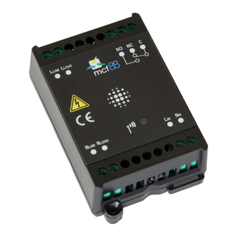
Solar Data Systems Solar-Log 10 User manual

Installation Manual
Solar-Log 10 (Bi-Directional Meter)

2
Dear Valued Customer,
Thank you for choosing Solar-Log®to monitor your PV plant.
Please read this installation manual carefully before installing the
Solar-Log®device. The Solar-Log 10 Meter is easy to install and
effective at monitoring the power consumption.
Technical support is available at (203) 702-7189 Monday through
Friday, 8:00 am to 5:00 pm, EST. Please prepare all relevant
information (Solar-Log®model, part number, problem description,
...) prior to calling, enabling technical support to help you finalize
the installation quickly.
Technical support can also be reached via e-mail at
Please leave this installation manual with the plant owner as a
reference guide.
Thank you.
Solar Data Systems, Inc.
23 Francis J. Clarke Circle
Suite 4A
Bethel, CT 06801
Phone: (203) 702-7189
www.solar-log.net

3
Table of Content
1 Introduction................................................................................ 4
2 Assembly ......................................................................................7
2.1 Meter Printed Circuit Board (PCB) ...................................................8
2.2 Meter Printed Circuit Board (PCB) Terminal Blocks ................10
3 Meter Technical Specifications............................................ 11
4 Safety Label Definitions & Information........................... 12
5 Precautionary and safety Information............................. 13
6 Meter Installation.....................................................................14
6.1 Mounting the Solar-Log 10 Meter.................................................... 15
6.2 Current Transformer Installation & Wiring....................................17
6.3 Current Transformer Installation...................................................... 19
6.4 Current Transformer Warning.......................................................... 20
6.5 AC Power & Current Transformer Wiring Diagram................... 21
6.6 Wiring the Printed Circuit Board (PCB)........................................22
6.7 Current Transformer Diagnostics ................................................... 24
6.8 Modbus RTU RS485 Wiring...............................................................27
7 Preventative / Scheduled Maintenance .........................29
8 Frequently Asked Questions..............................................30
9 Meter Limited Warranty....................................................... 32

4
1 Introduction
The Solar-Log 10 Meter measures electrical power for single (split)
phase and three phase power systems.
All relevant power components, such as currents, voltages, real
power, reactive power, and apparent power are measured.
The Solar-Log 10 Meter stores the measured values internally in the
device as well as on an external website. The Solar-Log 10 Meter
communicates with the Solar-Log®via Modbus-RTU RS485.
Installation must only be performed by qualified personnel following
this installation manual and all applicable local and national electri-
cal codes.
Solar Data Systems, Inc. and its representatives assume no respon-
sibility for damages or injury resulting from the improper installation
of the Solar-Log 10 Meter.
Check the voltage rating and configuration description on the de-
vice labels to ensure that it matches the intended electrical service
to be measured.
The Solar-Log 10 Meter, labelled for 120/208V service MUST NOT be
installed on a 277/480 volt or 347/600 volt service and vice versa.

5
Verify that the Solar-Log 10 Meter’s current transformer are sized
suitably for the current to be monitored.
CAUTION
Internal circuit card components are extremely sensitive to
electrostatic discharge. Prior to handling or touching internal
circuitry, be sure you are safely grounded by touching a
grounded metal object such as a conduit or an earth groun-
ded metal enclosure.
CAUTION
Follow all instructions and safety precautions in this guide.
Prior to performing any work turn off all power supplying the
equipment in which the meter is to be installed.
Only qualified personnel should work on the meter and
should be familiar with the technology and the hazards asso-
ciated with electrical equipment.
Beware of potential hazards and wear personal protective
equipment.
Only connect the meter as described in this manual.
Hazardous voltages can cause shock, burns or death. To
prevent exposure to hazardous voltages, disconnect and
lock out all power sources before servicing and removing
components.
Modifications made to the product may void the warranty.
Never work alone and before performing any tests, installa-
tion or maintenance on this equipment, isolate or disconnect
all hazardous live circuits and sources of electric power.

6
NOTE:
Please call the technical support team with any questions or for
installation assistance, (203) 702-7189.
Assume that all circuits are live until they have been com-
pletely de-energized, tested, and tagged. Pay particular
attention to the design of the power system. Consider all
sources of power, including the possibility of back feed.

7
2 Assembly
The single circuit board is mounted inside a NEMA 4x and NEMA 6
enclosure. (IP 66 and IP 67)
Fig. 1. Assembly

8
2.1 Meter Printed Circuit Board (PCB)
AC power, current transformers (CTs), and RS485 are connected to
the Meter PCB.
The AC power connections are labeled from 1 to 5 on the lower left
PCB corner, above the label “MAIN POWER INPUTS”.
The current transformers (CTs) connections are labeled 6 to 8 in
the lower middle of the PCB, above the label “CURRRENT SENSOR
INPUTS”. Connected CTs must match the related AC power voltage
input.
• CT A (CURRENT SENSOR INPUTS) must measure the current of
phase A (MAIN POWER INPUTS)
• CT B (CURRENT SENSOR INPUTS) must measure the current of
phase B (MAIN POWER INPUTS)
• CT C (CURRENT SENSOR INPUTS) must measure the current of
phase C (MAIN POWER INPUTS)
RS485 connections are labeled 9 to 10 in lower right hand of the
PCB above the label RS485.

9
1 2 3 4 5
6 7 8
9 10 11
Fig. 2 Meter Printed Circuit Board (PCB)
Power LED
State LED
RS485 Communication LED
RS485 Terminal
Current Transformer Terminal
AC Power Terminal

10
2.2 Meter Printed Circuit Board (PCB) Terminal Blocks
Number
in Fig. 2
Title Port
1 MAIN POWER INPUTS A / L1 Phase A
2 MAIN POWER INPUTS N Neutral
3 MAIN POWER INPUTS B / L2 Phase B
4 MAIN POWER INPUTS N Neutral
5 MAIN POWER INPUTS C / L3 Phase C
6 CURRENT SENSOR INPUTS A Black/White CT Phase A
7 CURRENT SENSOR INPUTS B Black/White CT Phase B
8 CURRENT SENSOR INPUTS C Black/White CT Phase C
9 RS485 + Plus
10 RS485 - Minus
11 RS485 GND

11
3 Meter Technical Specifications
Input Voltage Conguration Single (split) Phase or 3 Phase
Main Voltage Input 100-240VAC~, -15% / +10%
Input Power < 1.2 Watt
Current Transformer Primary* up to 200 A
Current Transformer Secondary 0 to 200 mA
Power Factor 0.0 - 1.0 CosPhi
Accuracy < 1 % with calibrated CTs
Line Frequency 50/60 Hz
Voltage Operating Rate +/- 10 % Of Rated Load
Temperature Range - 40F to 140F
Altitude 2000 Meters Maximum
Voltage Overload 10 %
Current Sensor Overload 10%, 100% for 1 minute
Pollution Degree Degree 4
Installation (Overvoltage
Category)
CAT III
Measurment Category CAT III
Enclosure Material NEMA 4X/6 // IP 66/67 :
Standards EN 62208, GOST
Standard Ranges* 1 Phase, 120/240 VAC: up to 200A
1 Phase (Split Phase), 120/240 VAC up to 200A
3 Phase, 120/208 VAC:up to 200A
*The maximum measurement (primary) current depends on the type of current
transformers (CTs). The available Solar-Log CTs are up to 200A.

12
4 Safety Label Definitions & Information
The Solar-Log 10 Meter may contain one or more of the following
labels.
Operator(s) should familiarize themselves with the meaning of each
label to minimize risk.
The presence of this label is a cautionary indicator identify-
ing a danger risk. The manual should be consulted prior to
proceeding.
The presence of this label indicates an electrical shock haz-
ard exists in the location or area where the label is placed.
Prior to proceeding, the AC power must be disconnected
and the manual consulted for safety information.

13
5 Precautionary and safety Information
CAUTION
Internal circuit card components are extremely sensitive
to electrostatic discharge. Prior to touching any internal
circuitry, be sure to discharge any static on your person by
touching a grounded metal object such as a conduit or an
earth grounded metal enclosure.
WARNING
The AC power connection labeled “MAIN POWER INPUTS”
screw down terminal on the meter printed circuit board
(PCB) exposes high voltage. This poses a risk of serious
injury and/or electric shock. Prior to performing any wiring
or other operations, switch off the AC power and read this
installation manual carefully. Only qualified personnel may
perform installation wiring. Installation and wiring must com-
ply with all local and national electric codes and regulations.
WARNING
NEVER open the Solar-Log 10 Meter cover without first
disconnecting the AC power. Failure to comply increases the
risk of serious injury and/or electric shock.
CAUTION
Always make sure that the enclosure is tightly closed and all at-
tached conduits are sealed. It is recommended to use additional
protection against environmental conditions like rain or dust.

14
6 Meter Installation
Appropriate installation steps
1. Install the Solar-Log 10 meter enclosure. Please carefully review
the mounting instructions in the next chapter of this installation
manual.
2. Install the current transformers (CTs) around the relevant wires
to be measured.
3. Connect the CTs to the relevant Solar-Log 10 Meter terminals.
4. Connect the AC power to relevant Solar-Log 10 Meter terminals.
5. Switch on the AC power.
6. Observe the Solar-Log 10 Meter diagnostics LEDs and make sure
they indicate the correct operation status.
7. Close the enclosure.
WARNING
Disconnect any relevant AC power and take out any relevant
fuses before proceeding with the installation. Only qualified
and trained personnel may perform work on electric power
lines in buildings.

15
6.1 Mounting the Solar-Log 10 Meter
Use appropriately sized mounting hardware to fasten the meter en-
closure to the selected mounting surface. The distance between the
4 mounting screws is 6.3” W x 4.33” H, as show in Fig. 3 Enclosure
Dimensions (above).
All necessary cable and wire holes, and connected conduits need to
Fig. 3 Enclosure Dimensions.

16
be sealed to maintain the necessary protection class of the NEMA
4x enclosure.
Drill holes according to necessary conduits
WARNING
Do not drill into the Solar-Log®Meter printed circuit board
(PCB) - it will damage it and it will not work anymore!

17
6.2 Current Transformer Installation & Wiring
The Current Transformers (CTs) are connected via the “CURRENT
SENSOR INPUTS” terminal block.
“CURRENT SENSOR INPUTS” A is the input for Phase A
“CURRENT SENSOR INPUTS” B is the input for Phase B
“CURRENT SENSOR INPUTS” C is the input for Phase C
The necessary Solar-Log®CTs are included with every Solar-Log 10
Meter. Each Solar-Log®CT is calibrated (and marked either A, B, or
C) and MUST connect to the relevant CT input port (CURRENT SEN-
SOR INPUTS A, B, or C). The above process leads to the advertised
meter accuracy. Not following these instructions can result in less
accurate power measurements.
Split core CTs are easily installed by wrapping them around already
installed power wires.
Fig. 4 Split Core Current Sensor.

18
Technical Current
Transformer Data
Solar-Log®CT200 A–o
Open transformer (folding mechanism) 1000:1
Primary measurement 200 A
Secondary output 200 mA / max. 6.7 V
Accuracy < 1 % between 1A - 200A (*)
Outer Dimensions 2 inch x 2 inch x 0.5 inch
Opening 0.75 inch
Cable length 10 feet (it can be extended up to 30
feet with 0.75 inch2cable)
(*) for Solar-Log 10 Meter calibrated CTs only

19
6.3 Current Transformer Installation
One Current Transformer (CT) is used per phase. The split core CT
opens by pulling the top part off the assembly. No tool is required.
Installing the CTs in the correct orientation is essential because it
determines the direction of the AC power flow.
The arrows on the Solar-Log®CT stickers show the direction of the
building load power(consumption).
For example, if the Solar-Log 10 Meter is used for metering the
power at the main utility connection of a home, the arrows on the
Solar-Log®CTs will have to point from the utility (outside) into the
house (inside).
Fig. 5 Solar-Log®CT 200A-o

20
6.4 Current Transformer Warning
WARNING
Connecting the current transformers (CTs) in the open
Solar-Log 10 enclosure must be done with extreme caution,
because of the high voltage electricity connected to the
printed circuit board (PCB). Coming into contact with the
high voltage carrying component is dangerous to life and
limb. Only trained, qualified personnel may perform the CT
installation.
The CTs are wrapped around the relevant phase wire first
and then connected to the matching phase on the current
sensor terminal on the Solar-Log 10 PCB.
The current transformers (CTs) connections are labeled 6
to 8 (Fig. 2 Meter Printed Circuit Board (PCB)) in the lower
middle of the PCB, above the label “CURRRENT SENSOR
INPUTS”. Connected CTs must match the related AC power
voltage input.
Each CT connects to two terminals, one labeled “BLK” for
black and the other “WHT” for white.
The CT labeled phase A connects to the “CURRENT SENSOR
INPUTS” terminal A.
The black wire connects to the “BLK” terminal (upper row)
and white wire to the “WHT” terminal (lower row).
Repeat the above for the remaining phases B and C.
Table of contents
