Nic WA-5F User manual

WA-5F Service Manual
Document
Number NIC-704-2015-01 Date of
Issue Apr. 14, 2017
Control
Department Technical Center Page 1/36
1
WA-5F
Service Manual
Nippon Instruments Corporation
Technical Center
Date Prepared
Checked Approved
First Edition
Apr. 14, 2017
Kinoshita
Yamada Kato
WA-5F Service Manual
Document
Number NIC-704-2015-01 Date of
Issue Apr. 14, 2017
Control
Department Technical Center Page 2/36
2
Revision History
Revision No.
Revision Date
Reason for Changes
Prepared
Approved
01 Apr. 14, 2017 First Edition issued Kinoshita Kato
Distribution List
Destination Date Destination
Date Destination
Date
President -
Executive Director -
Application Technology Dept.
-
Sales Dept. -
R&D Dept. -

3
Atmospheric Mercury Analyzer
Mercury/WA-5F Service Manual
Contents
1. Introduction....................................................................................................................5
Overview ................................................................................................................5
Basic configuration of this system ..........................................................................5
Part names and functions of the Mercury Analyzer ................................................6
Front (inside front cover) .................................................................................6
Back................................................................................................................7
Internal components viewed from the right......................................................8
Internal components viewed from the left........................................................9
Intended readers of this Service Manual................................................................9
2. Safety instructions.......................................................................................................10
Meaning of safety alert symbols...........................................................................10
Cautions on installation ........................................................................................10
Cautions on maintenance.....................................................................................10
3. Maintenance................................................................................................................11
Inspection items ...................................................................................................11
Daily inspection.............................................................................................11
Annual inspection..........................................................................................12
Errors and warnings .............................................................................................13
Troubleshooting....................................................................................................16
Decrease in sensitivity...................................................................................16
Abnormal blank value....................................................................................17
Abnormal increase in sensitivity....................................................................17
Maintenance.........................................................................................................18
Leak check....................................................................................................18
Replacing the septum....................................................................................19
Cleaning the gas scrubbing bottle and dehumidifying bottle .........................19
Detaching and attaching the cover................................................................20
Detaching and attaching the collector tube (H2)............................................20
Cleaning the absorption cell..........................................................................21
Cleaning the joints.........................................................................................22

4
How to reduce the blank value of collector tubes..........................................23
4. How to remove and install the components.................................................................24
Collector tube adaptor..........................................................................................24
Heater H1.............................................................................................................24
Heater H2.............................................................................................................26
Gas scrubbing bottle and dehumidifying bottle.....................................................26
Cell.......................................................................................................................26
Adjusting the sensitivity of the optical system.......................................................27
Mercury lamp........................................................................................................29
Photoelectric tube preamplifier.............................................................................31
Second collector tube...........................................................................................31
Solenoid valve and active carbon filter.................................................................32
Flow sensor..........................................................................................................33
Air pump...............................................................................................................33
Control boards......................................................................................................34
Switching power supply........................................................................................35

5
1. Introduction
Ensure to refer to this Service Manual before conducting the inspection, repairs, or
maintenance of the Mercury Analyzer WA-5F.
Overview
The Mercury/WA-5F is a mercury measuring system which allows the amount of
mercury collected in a dedicated mercury collector tube to be quickly measured with
high sensitivity and in a wide range through simple operations.
The operations are carried out on a PC where the measurement results can be
analyzed through various methods such as statistical calculations.
Basic configuration of this system
This system consists of the following:
(1) Mercury Analyzer: WA-5F
(2) Data analysis / System control software: WA5Win
(3) Standard accessories
(4) Personal computer

6
Part names and functions of the Mercury Analyzer
* This section is identical to the content in the Instruction Manual.
Front (inside front cover)
No.
Item Remarks
Standard gas inlet Comes with a built-in septum.
Heating furnace (H1) for collector tube Comes with a built-in cooling fan.
Mounting port for collector tube Made of fluoride resin.
Electronic cooling unit
Gas scrubbing bottle
Removes any acidic gas.
- For measuring the mercury in the
ambient air:
the standard buffer solution (1+1), pH
6.86
- For measuring the mercury in the
samples of reducing vaporization:
NaOH, 0.1M
Dehumidifying bottle Removes moisture.
Opening for connecting to the detector
Valve for connecting optional units (EV)
Flow control needle valve Adjusted to 0.5 L/min.
1
2
3
4
5
6
7
9
8

7
Back
No.
Item Remarks
OUTLET Connection port for outlet gas tube (O.D.: 6 mm)
Main power switch
Connection port for power cable 100-240 VAC
Fuse 100V 10A or 250V 5A
AC OUT Power outlet for Auto Tube Changer
* Linked with the main switch.
LAN port for PC connection Port for a LAN cable.
Serial port (Not used)
Connection port for dry gas meter
Option (Not used)
Auto Tube Changer (Signal) Port for control signal cable
Auto Tube Changer (Power) Port for power cable
1
2
3
4
5
6
7
8
9
8
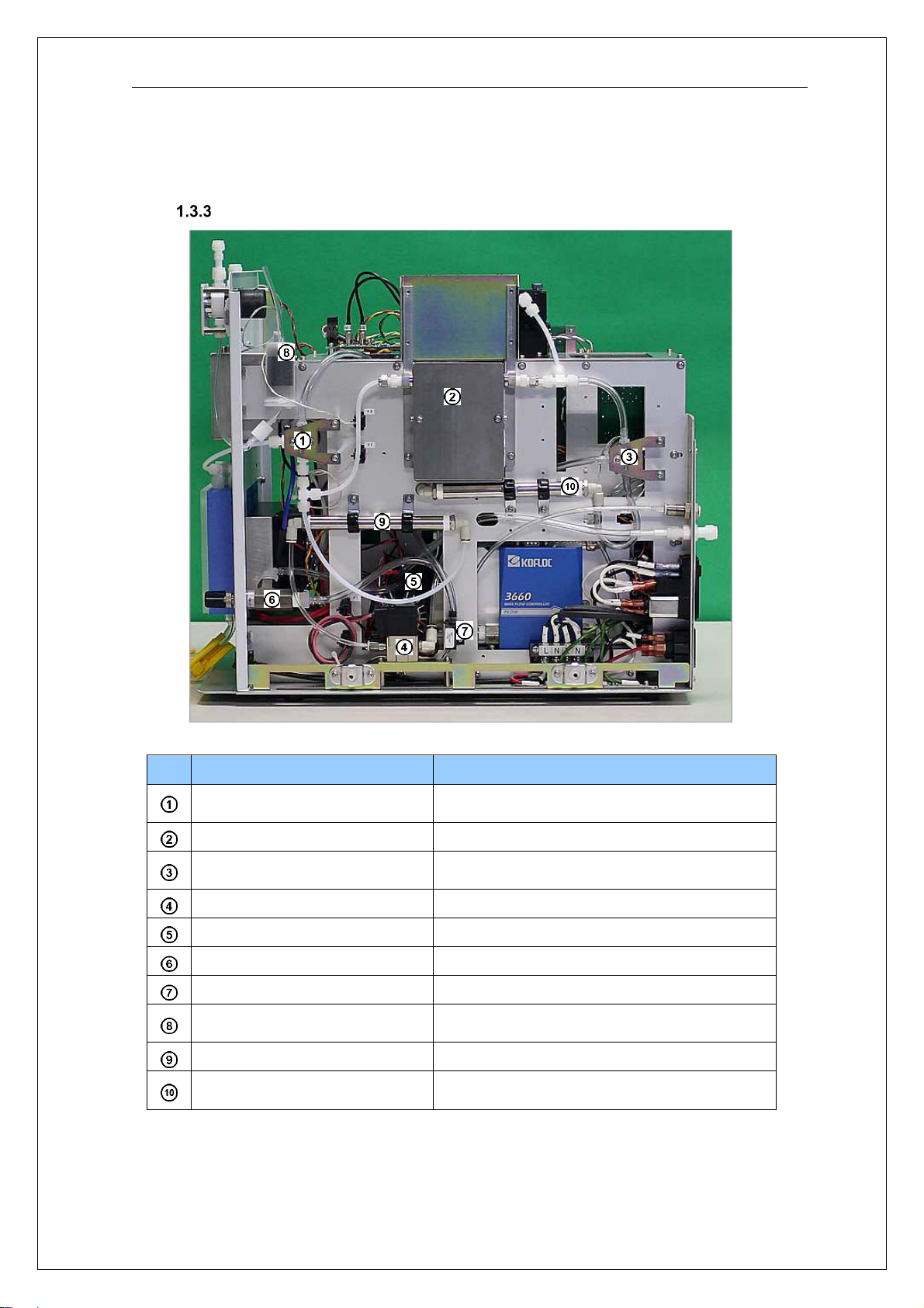
Internal components viewed from the right
No.
Item Remarks
Valve V1 Switches between the sampling/detection
lines.
Re-collecting furnace (H2) Comes with a built-in cooling fan.
Valve V2 Switches between the detection/bypass
lines.
Valve VF Prevents backflow.
Air pump
Flow control needle valve Adjusted to 0.5 L/min.
Flow sensor For measuring the flow rate
Active carbon for carrier gas For purging carrier gas during
transfer/sampling
Active carbon for carrier gas For purging carrier gas during measurement
Active carbon for outlet gas For removing mercury from the outlet gas
after measurement

9
Internal components viewed from the left
No. Item Remarks
Main circuit board
SSR1 For controlling the H1
SSR2 For controlling the H2
Power board for optical system
Power board for electronic cooling
unit
Power board for main circuit board
MFC control board
Intended readers of this Service Manual
The intended readers of this manual are engineers who have received proper training
and will be dispatched to a site or work at a factory to conduct the inspection, repairs,
or maintenance of the system.
6
1
2
3
4
5
7

10
2. Safety instructions
Observe the following instructions to ensure safety.
Meaning of safety alert symbols
Warning
indicates safety instructions required to prevent severe injury
or death.
Caution indicates safety instructions required to prevent moderate or
minor injury or property damage.
Cautions on installation
Warning
• To prevent an electric shock, be sure to connect the grounding wire.
• To prevent an electric shock and fire, be sure to check the power cables
and plugs for any damage.
Cautions on maintenance
Warning
• Shut off the power supply before starting the maintenance work.
Otherwise, you may suffer an electric shock.
Caution
• Conduct the maintenance of the heater section only after the power has
been turned off and the heater has cooled down. Otherwise, you may burn
yourself.
• Be careful when touching any glass parts. Otherwise, you may get injured
if they are broken.
• Be sure to discharge any liquids accumulated in the drain tank once the
work is complete. In addition, before starting the discharge, be sure to turn
off the power.

11
3. Maintenance
* This chapter is identical to the content in the Instruction Manual.
To keep the system in proper condition, observe the instructions related to inspection,
repairs, and maintenance.
Inspection items
Daily inspection
Inspection before starting work
Inspection items Criteria Corrective action
Gas scrubbing bottle Must be clean. Clean.
Status Must be any mode other than
OFF-LINE. Connect the cables.
Check the ports.
System check Must be complete without any
errors. Check the message.
Measurement method
The measurement method is
properly specified in the
system setting.
Change the setting on “Setup”
screen – “System” tab.
Error/Warning At the expiry of the standby
countdown timer, no errors or
warning messages are
displayed on the screen.
Inspection during measurement
Items Criteria Corrective action
Blank value After the purge measurement
has been repeated, the HEIGHT
value on LOW side must be
0.0002 or less.
Repeat the blank
measurement or clean the
line.
Calibration curve The calibration curve created
with the standard solution must
have a correlation coefficient of
0.9990 or higher.
Replace the collector tube
or clean the line.
Sensitivity The slope of the calibration curve
must be within ±30% of the slope
at the time of delivery.
Replace the collector tube
or clean the line.
History The blank value obtained
immediately after measurement
of the standard gas must be up
to 2% of the amount of mercury
detected immediately before the
measurement.
Clean the gas scrubbing
bottle and replace the
mercury collector tube.
Accuracy The standard gas must be
measured within ±5% accuracy
after measurement of actual
samples.
Review the method and the
sample volume.

12
Annual inspection
Annual inspection
Inspection items Criteria Corrective action
Mercury collector tube The quartz tube must be clean.
No discoloration of the quartz
wool.
Replace the mercury
collector tube.
Absorption cell Must be clean. Disassemble and clean the
absorption cell or replace it.
Flow rate No variations exceeding 0.02
L/min. Clean the needle valve or
replace the pump.
Output voltage of
detector (Ref)
Must be 4 ± 0.5V on the
Maintenance screen of
WA5Win.
Wipe any dirt and stains off
the lamp, lens, etc.
Active carbon filter No damage or discoloration. Replace.
Air pump
No abnormal noise.
During the flow rate check of the
system checks, adjust the flow
rate to 0.5 L/min, and the flow
rate must be stable.
Replace.
Electronic cooling unit
The (internal) temperature of the
cooling unit must be at least 8°C
lower than the room
temperature.
Repair.

13
Errors and warnings
Measurement is disabled in the event of an error. You cannot resume measurement until the
cause of the error is removed and either the main unit is powered on again or “Run” – “Reset”
is executed from the menu.
(1) Warning message
Message Description and corrective action
STAND-BY xx:xx Appears for 20 minutes after the power is turned
on.
Because the heater and the optical system are
still unstable during the countdown period, any
measured data in the period is unreliable.
Close the door of the TC-WA.
(appears only when the TC-WA is
connected.)
Appears if the door of the TC-WA is open when it
starts running.
The process resumes when the door is closed.
(2) Error message 1
Error
code
Message Description and corrective action
01 A/D FULL
The voltage of theA/D
converter of the optical system
has reached its upper limit.
Generated if the voltage of SIG1 or REF is 5V or
higher.
If the error occurs on the SIG side, it may be caused
by dirt or stains on the cell. If the error occurs on the
REF side, it may be caused by an increase in the
lamp’s light quantity, an increase in the sensitivity of
the photoelectric tube, or a fault in the circuit.
02 LAMP BROKEN
The light quantity of the lamp
(REF voltage) has dropped
below its lower limit.
Generated if the REF voltage is 0.5V or lower.
It may be caused by the degradation of the lamp, a
fault in the photoelectric tube for light quantity
compensation, or a fault in the circuit.
03 CELL DARK
The absorption cell is not clean.
Generated if the SIG voltage is 0.5V or higher.
Clean the absorption cell.
04 MOTOR ALARM (PUMP)
An alarm is generated from the
motor driver IC for air pump.
Generated if the motor driver IC for air pump has an
error.
Restart the system. If the error still persists, contact
us.
06 COOLING ERROR (H1)
FAN1 may not be running. Generated if the temperature of H1 is not lower than
150°C on completion of the cooling process
. The fan
may not be running or the cooling time may be too
short.
07 COOLING ERROR (H2)
FAN1 may not be running. Generated if the temperature of H2 is not lower than
300°C on completion of the cooling process
. The fan
may not be running or the cooling time may be too
short.
08 COOLING ERROR (H3)
FAN1 may not be running. Generated if the temperature of H3 is not lower than
150°C on completion of the cooling process
. The fan
may not be running or the cooling time may be too
short.

14
09 HEATER BROKEN (H1)
The temperature of H1 does
not rise enough.
Generated if the temperature of H1 is below 400°C
on completion of the transfer.
Turn off the power and then restart the system. If
the error still persists, contact us.
10 HEATER BROKEN (H2)
The temperature of H2 does
not rise enough.
Generated if the temperature of H2 is below 400°C
on completion of the measurement.
Turn off the power and then restart the system. If
the error still persists, contact us.
20
FLOW ERROR
The flow rate is too low. Generated if the flow rate drops below 0.2 L/min
during measurement.
Check that the pump is running properly. Check the
line for any disconnection.
The errors from 01 through 04 are detected while the system status is READY.
When the errors from 06 through 10 and 20 are detected, the system bypasses the
subsequent sequences and proceeds to the cooling process. When H1 and H2 have
cooled down, the system stops.

15
(3) Error message 2
Potential errors when the TC-WA is connected
Error
code
Message Description and corrective action
11
HEATER BROKEN (H3)
The temperature of H3 does not
rise enough.
Check whether the TC-WA is
turned on.
Generated if the temperature of H3 is below 400°C
on completion of the transfer.
Check the power cable and switch of the TC-WA. If
there is no problem with them, contact us.
12
TC-WA TIME OUT
ERROR (TABLE)
The operation of the table motor
cannot be completed.
A failure has occurred while the table is actuated.
Turn off the power, open the front cover, and check
the status.
If the problem cannot be corrected, contact us.
13
TC-WATIME OUT ERROR (LIFT)
The operation of the lift motor
cannot be completed.
A failure has occurred while the lift is actuated.
Turn off the power, open the front cover, and check
the status.
If the problem cannot be corrected, contact us.
14
TC-WA LIFT UP ERROR
The lift does not move up. Generated if the lift does not move up during
loading of the collector tube into the heating
section.
Turn off the power, open the front cover, and check
the status.
If the problem cannot be corrected, contact us.
15
TC-WA NO SAMPLE
The measured collector tube does
not move down.
Generated if the measured collector tube does not
move down.
Turn off the power, open the front cover, and check
the status.
If the problem cannot be corrected, contact us.
16
TC-WA MOTOR ALARM (TABLE)
An alarm is generated from the
motor driver IC for table.
Generated if a failure occurs in the motor driver IC
for table.
Restart the system. If the error still persists, contact
us.
17
TC-WA MOTOR ALARM (LIFT)
An alarm is generated from the
motor driver IC for lift.
Generated if a failure occurs in the motor driver IC
for lift.
Restart the system. If the error still persists, contact
us.
When the error 11 is detected, the system bypasses the subsequent sequences and
proceeds to the cooling process. When H3 has cooled down, the system stops.
When the errors from 12 through 17 are detected, the system immediately cancels the
measurement and stops.
(4) Error message 3
Potential errors when the gas meter is connected
Error
code
Message Description and corrective action
19
GAS METER ERROR Generated if the sampling pulse from the gas
meter cannot be detected during measurement in
the direct sampling mode.
When the error is detected, the system bypasses the subsequent sequences and stops.

16
Troubleshooting
Decrease in sensitivity
A decrease in peak sensitivity is mainly caused by the following three factors:
Problems with the standard gas
Leakage from the syringe, contamination of the syringe, or abnormal temperature
of the Mercury Vapor Calibration Box.
Problems with the system
Malfunction of heaters/valves or leakage
* If the leakage does not stop, disconnect the joint on the outlet side of the
dehumidifying bottle, and plug the inlet of the tube leading into the main unit
with your finger. If the leakage is still observed in this condition, there is a
problem inside the system. Open the cover and retighten the Teflon joint.
Contamination/degradation of the line
Contamination of the collector tube, scrubbing solution, or joints
Contaminated/degraded points can be identified by feeding the standard gas
from intermediate points in the line.
e.g. Disconnect the joint at the outlet of the dehumidifying bottle and connect the
disconnected tube to the standard gas inlet. Carry out measurement at this point.
If the sensitivity recovers, there is a problem with the line upstream of the
dehumidifying bottle. If the sensitivity does not improve, there is a problem with
the line between the dehumidifying bottle and the absorption cell.
* If the tube cannot be directly connected to the inlet, use a short tube or a reducing
Teflon joint.

17
Abnormal blank value
An increase in a blank value is mainly caused by the contamination of the gas line with
mercury. If contaminated components are the cause of the increase, it becomes difficult
to measure low concentrations of mercury. Identify the location where the problem
occurred, and clean or replace the component.
The location of the problem can be identified by installing the mercury removal filter at
an intermediate point in the line and performing a comparative measurement. Using a
Tygon tube or other means, install activated carbon for filter or a mercury collector tube
at an intermediate point in the line, and measure the amount.
* When you take a sample of the standard gas, mercury particles may adhere to the
syringe needle and contaminate the standard gas inlet. Wipe the tip of the needle
with Kimwipes or other material before feeding the gas.
Abnormal increase in sensitivity
An abnormal increase in peak sensitivity may be caused by the following two factors:
Problems with the standard gas
- the syringe is contaminated with mercury,
- the indicated temperature of the Mercury Vapor Calibration Box is low, or
- the septum of the Mercury Vapor Calibration Box is contaminated.
Decreased flow rate between H2 and the absorption cell
- leakage,
- clogging in the collector tube, or
- a failure in the pump

18
Maintenance
Leak check
Check the line for any leakage from a loose joint or other points. Disconnect the
standard gas inlet and plug the top of the collector tube with your finger to stop the
supply of carrier gas. At this point, the flow rate should drop to near zero. If the flow rate
does not drop, there is a leak from the degradation of the septum, a loose joint, etc.
Caution
After the completion of the leak check, slowly slide your finger off the top of
the collector tube. If you burst it open, the collecting agent may be scattered
into the gas line, thus making normal measurement impossible.
If any leakage is detected, check the connections. If retightening does not stop the
leakage, disconnect a joint at an intermediate point in the line and plug the line with your
finger to identify the location of the leak.

19
Replacing the septum
Remove the standard gas inlet.
Remove the box nut on the side where the septum
is placed.
Replace the septum with a new one.
Install the parts in the order shown in the left
figure.
Cleaning the gas scrubbing bottle and dehumidifying bottle
Open the front cover.
Detach the collector tube, and remove the screws
fixing the connecting port of the collector tube.
Remove the transparent plate of the electronic
cooling unit.
Remove the funnel and roller clamp of the gas
scrubbing bottle and dehumidifying bottle.
Pull out the gas scrubbing bottle and the
dehumidifying bottle, and clean them after
detaching the silicone tube.
* Do not clean the silicone tube, but instead replace it
with a new one.

20
Detaching and attaching the cover
How to detach:
Turn off the power and disconnect all cables.
Remove the 2 screws on the back and the 4 screws
on both sides.
Slide the cover towards the back.
How to attach:
Place the cover on the back of the main body.
Close the cover while paying attention to the lugs (4
places) inside the cover.
Install and tighten the screws on the back and on
both sides.
Detaching and attaching the collector tube (H2)
Remove the cover of the system.
Remove the reducing Teflon joints (FLW-30-6RU4-S)
and pull out the collector tube from H2.
* When attaching the joints, first tighten them lightly by
hand and then further tighten them about 1/6 turn with a
wrench. After tightening, check that the tubes do not
come off when pulled.
(The joints will break if tightened too much.)
Check the quartz tube and wool of the collector tube for
any dirt or stains.
If the wool is discolored or if there is a gap in the
wool, change it.
Reverse the procedure to attach the collector tube.
Other manuals for WA-5F
1
Table of contents
Other Nic Measuring Instrument manuals


