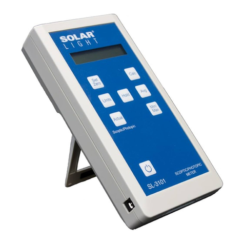
Solar Light SnP Meter SL-3101 User manual

100 East Glenside Avenue • Glenside, PA 19038 • USA • P 1.215.517.8700 • F 1.215.517.8747
USER MANUAL
SnP Meter™- Model SL-3101
(Version 1.00)
Last Revision: SL/Manuals/Specialty/SL3101_09/2017

Solar Light Company, Inc.
2
©2009 Solar Light Company. All rights reserved.
100 E. Glenside Ave
Glenside, PA 19038
USA
tel: 215/ 517-8700
fax: 215/ 517-8747
US Patent Numbers 5,946,641 and 5,790,432
ProComm is a registered trademark of Symantec Corporation.
Windows is a registered trademark of Microsoft Corporation.
Document No. D-IM-SL3101MAN-01-R00
Printed in the United States of America.

Solar Light Company, Inc. 3
Contents
USER'S GUIDE 1
CONTENTS 3
INTRODUCTION 5
SL-3101 DESIGN CONCEPT 5
MAJOR FEATURES 6
CURRENTLY SUPPORTED SENSORS 6
QUICK START 7
METER OPERATION 7
DISPLAYING CALCULATED VALUES 7
MEASURING WITH SL-3101 8
CONTROLS AND INDICATORS 9
DISPLAY 9
KEYPAD 10
AUDIBLE SIGNALS 11
ERROR MESSAGES 11
SETUP 12
METER SETUP 12
REAL TIME CLOCK AND CALENDAR:FUNCTION “T” AND “D” 12
RS232 DATA PRINTING:FUNCTION “O” 13
SENSOR SETUP 13
PRACTICAL USE OF THE SNPMETER 13
DATA MANAGEMENT 18

Solar Light Company, Inc.
4
DATA LOGGING 18
DATA PROCESSING 18
INTERFACES 21
SENSOR INTERFACE 21
SERIAL AND EXTENSION PORT 22
DIGITAL CONTROL LINES 24
TECHNICAL SPECIFICATIONS 26
MAINTENANCE AND TROUBLESHOOTING 27
METER CALIBRATION 27
TABLE OF FIGURES 28
INDEX 29

Solar Light Company, Inc. 5
Introduction
The Personal Measurement Assistant Model SL-3101 is a sophisticated measuring instrument that
combines the user-friendliness of simple meters.
SL-3101 Design Concept
The combination of simplicity of use and enhanced features was possible thanks to the
implementation of microprocessor technology and an innovative architecture.
The meter itself is programmed to perform the tasks common to most sensors. The information
specific for a particular sensor is stored in a nonvolatile memory built into the sensor itself. It includes
identification information, signal-processing algorithms, a description of the data presentation, and
the current setup of the sensor.
AMPLIFIERS
DISPLAY
CENTRAL
PROCESSOR
AND
MEMORY
SYSTEM
KEYPAD
SL-3101
DETECTOR
DETECTOR
MEMORY
SENSOR
CONNECTOR
AND CABLE
Figure 1 Architecture of the SL-3101

Solar Light Company, Inc.
6
Upon connection of a sensor the SL-3101 identifies it, downloads the contents of the sensor’s
memory into the operating memory, updates its setup and executes the downloaded code, if
appropriate.
This approach allows for an unlimited number of sensors to be supported by the SL-3101. It
configures itself to the specific features of each sensor and the custom setup of the measurement
process.
Major Features
Measuring with the SL-3101 is as simple as with the usual single sensor and meter. Plug a sensor
into the input socket, turn ON power and read the display. The many additional capabilities of the
SL-3101 include:
•User selectable system of units
•Tracking of the extremes of the signal (min., max., avg.)
•RS232 serial interface
•Digital inputs and outputs to control external devices
Currently Supported Sensors
The SL-3101 currently includes the following sensors:
•Photopic
•Scotopic
The SL-3101 can be used in any application where an accurate measurement is required, especially
if multiple quantities are measured or the enhanced functionality of the meter is desired. Potential
applications include:
•laboratory measurements
•outdoor measurements

Solar Light Company, Inc. 7
Quick Start
While sophisticated and powerful, the SL-3101 is a user-friendly instrument allowing for simple
“plug-and-play” operation.
Meter Operation
1. To operate the meter, simply connect the sensors.
2. Turn the meter on by pressing the On/Off key.
3. Zero out the readings by placing the sensors upside down on a flat opaque surface so the
sensors are covered and not exposed to light. Read the display. If the readings are not zero or
fluctuating around zero press the Zero key. This step can be skipped once you know the
characterization of your sensors. If they always read zero then the step can be skipped.
4. Point the sensors at the desired source.
5. Read the meter.
Displaying Calculated Values
Press the Calc key to display the Visual effective, Brightness and S/P Ratio calculated values.
These values are in a continuous loop by pressing the Calc key.
To show both photopic and scotopic readings at the same time press the Actual key.
Pressing the Units key toggles the units from lux to foot candles (fc).

Solar Light Company, Inc.
8
Measuring with SL-3101
To perform measurements with a SL-3101 the following steps should be followed:
1. Power ON the SL-3101 by pressing the On/Off button. If the meter does not respond attach the
optional external power supply. The unit will be powered ON whenever connected to the external
power supply. The SL-3101 will turn itself OFF after 3 minutes of inactivity if no sensor is
attached.
2. Plug the selected sensor into the sensor input located on the side of the meter. The meter will
indicate the connection by two beeps and the display will show the measurement result. Squeeze
the locking arms of the sensor plug while connecting or disconnecting it.
3. In order to turn the SL-3101 OFF press the On/Off key. If the unit is connected to external
power, it will remain powered up and pressing the On/Off will have no effect.
Refer to "Controls and Indicators" on page 11 for detailed description of the SL-3101 "data mode"
display.

Solar Light Company, Inc. 9
Controls and Indicators
Display
When the meter is turned ON, it displays a start-up
screen, Figure 2, while performing the hardware test.
The software version number of the meter is briefly
displayed.
Then, the display goes into the "data mode". If a sensor
is attached, the measurement results are shown in
Figure 3. Otherwise the screen indicates that there is no
sensor connected, Figure 4.
The HOLD function is activated by pressing the HOLD
key. When the data is flashing, the contents of the display are frozen; however, the measurements or
min/max/avg. (if enabled) will continue in the
background. Pressing the HOLD key again reactivates the continuous data display.
The Low and High tracking can be initiated by pressing the Min/Max key. The same key clears the
setting. The tracking of extremes starts from the moment the feature is activated. To re-start the
tracking, turn the feature OFF then back ON by pressing the Min/Max key twice.
Averaging is activated by pressing the Avg key. The averaging starts from the moment the feature is
activated. To re-start the averaging, turn the feature OFF then back ON by pressing the Avg key
twice.
Version:1.26
Figure 2 Start-up screen of the SL-3101
meter.
No Detector
Figure 4 Display in the "data mode"
with no sensor connected.
1.002 Lu
x
3.001 Lux
Figure 3 Display in the “data mode"
with sensor connected.

Solar Light Company, Inc.
10
lux
f c
The instantaneous reading is displayed with the currently selected units to the right of the
measurement result. If alternative units are available, pressing the Units key will convert the result to
alternative units. They can be selected by pressing the Units repeatedly. After the last unit selection is
reached, pressing the Units key will bring the display back to the initial unit selection.
Calculations can be initiated by successively
pressing the Calc key. Press the Calc key and the
Visual Effectiveness value is displayed on the
screen. Press the Calc key again and the
Brightness value is shown. Pressing the Calc key
for a third time displays the S/P value. A fourth
press will again display the Visual Effectiveness,
and so on. While in Calc mode, pressing the
Actual key will return to the actual Scotopic and
Photopic values.
Keypad
The keys of the SL-3101, Figure 6, have a tactile feel and an audible signal is generated when the key
is pressed.
The On/Off key toggles the power to the meter. It is only active in
the display mode.
The Actual key displays the Scotopic and Photopic values. Pressing
the HOLD key, freezes the information on the LCD, without
affecting the measurement and data collection process. The
displayed data will begin to flash. While in the “hold mode”
pressing HOLD a second time reactivates display updating.
The Min/Max key initiates the Low and High tracking. The same
key clears the setting. The tracking of extremes begins from the
moment the feature is activated. To re-start the tracking turn the
feature OFF then back ON by pressing the Min/Max key twice.
High and low values will be reset to zero on restart of the Min/Max
function.
The Avg key initiates averaging. The same key clears the setting.
The averaging begins from the moment the feature is activated. To
re-start the averaging turn the feature OFF then back ON by
pressing the Avg key twice. The average value will be reset on
restart of the Avg function.
Figure 5 Pressing the “Units” key converts
the measurement result into one of the
available unit systems.
SL-3101
On/Off SCOTOPIC/PHOTOPIC
METER
Units
Actual
Ze ro Set
100% Ca lc
Avg
Min/
Max
Hold
Figure 6 Keypad configuration of the
SL-3101

Solar Light Company, Inc. 11
The Zero key will zero any offset for the sensor. This function is also useful for relative
measurements between two sources.
The Set 100% key is inactive on this model.
Audible Signals
Certain conditions cause a generation of an audible signal to attract the user’s attention. The
conditions generating an audible signal are listed in Table 1.
Table 1 Conditions causing a generation of an audible signal.
power on 1 long beep
activation of any key 1 short beep
acceptance of an newly connected sensor 2 short beeps
sensor disconnected 3 short beeps
Sensor out of range (max value exceeded) Short ticks
Error 1 long beep
Error Messages
When an erroneous condition is detected by the SL-3101 an error message is displayed to indicate the
nature of the problem.
Table 2 Error codes and messages
Code Message on LCD Description of the problem
02 Upgrade software The sensor requires a higher version of the software controlling the SL-
3101. The message is displayed immediately after the new sensor is
connected. Contact the manufacturer for upgrade.
03 Out of cal The sensor is due for calibration. The sensor should be returned to
manufacturer for re-calibration.

Solar Light Company, Inc.
12
Setup
Meter Setup
Real time clock and calendar: Function “T” and “D”
The real time clock and calendar provides the information for time-stamping of the recorded data.
To set the real time clock/calendar, follow these steps:
1. Connect the SL-3101 to an available serial port on a PC using an AT modem cable.
2. Start a communications program such as ProComm or Windows Terminal or HyperTerminal.
3. Configure the Com Port as follows:
•Baud rate 19200
•Handshake None
•Data bits 8
•Parity None
•Stop bits 1
4. Press Enter to get a menu from the SL-3101. (Figure )
5. Press “D” to set the date or “T” to set the time.
SL-3101 Ver:1.26 2008 S/N:01234 9/23/2008 10:36:19
T - Set timehh:mm:ss
D - Set date mm/dd/yy
O - Toggle RS232 data printing
Figure 7 setup screen for the SL-3101 meter.

Solar Light Company, Inc. 13
RS232 data printing: Function “O”
The RS232 data printing function allows the user to display and/or capture the data from the sensor to
a file via RS232. Follow steps 1-4 in the Real time clock and calendar section for the computer
connection and display. Press “O” to toggle the data printing on and off. The data is updated and
displayed about three times per second.
Open a file to capture the data if it is to be stored. Before the SL-3101 is connected a description can
be annotated. For example, light source type, distance, filters, experiment name, etc. Connect the SL-
3101 and press Enter. Press “O” to toggle the RS232 on when the sensor setup is complete and you
are ready to start storing data.
The data format displayed is shown in Table 3 and the description is shown in Table 5.
Sensor Setup
The sensors are equipped with a non-volatile memory to store configuration information specific to a
particular sensor. When the sensor is connected, these configuration parameters are read from the
sensor and used to set up the PMA.
The meaning behind the meter’s measurements
1. What is scotopically enhanced lighting?
Scotopically enhanced lighting research suggests that certain lamps containing more blue in
the spectrum will be more visually efficient than lamps with less scotopic content, even if
they have the same (photopic) lumen and efficacy values. The use of scotopically enhanced
lighting can therefore be used at lower energy levels while maintaining equal vision, or visual
effectiveness.
The functioning factor used in scotopically enhanced lighting is called the S/P ratio, which
evaluates the spectrum of any lamp on the basis of the Scotopic function in comparison to
the Photopic function. This ratio is independent of lighting levels for fluorescent lamps, and
can be provided by lamp manufacturers for any light source that they manufacture. For most
fluorescent and HID lamps the S/P values vary between 0.8 and 2.5, with the higher values
representing lamps with more blue in their spectrum.i

Solar Light Company, Inc.
14
Human perception of light
follows two distinct spectral
response curves, depending
on the light level. The
spectral response curve that
dominates during typical
daytime conditions is the
photopic response curve,
and results from the “cones”
in human eyes. During very
low light conditions,
perception follows the
scotopic response curve,
which in contrast results from
the “rods” in the human eye.
The peak spectral
luminous efficacy of the
scotopic response curve
(1700 lumens per watt, at
507 nanometers) is
significantly greater than that of the photopic response curve (683 lumens per watt, at 555
nanometers)ii.
Traditionally, light levels have only been measured in accordance with the photopic
response curve. In recent years however, interest has grown in scotopic light due to the
human eye’s ability to perceive objects more clearly from sources with enhanced scotopic
quality, particularly at night.iii

Solar Light Company, Inc. 15
2. S/P ratio
The factor S/P is the ratio of scotopic luminous quantity to photopic luminous quantity for the
lamp spectral power distribution. From a given photopic quantity, the analogous scotopic
quantity can be found by multiplying the photopic quantity by the value of the S/P ratio.
Natural daylight has an S/P ratio of close to 2.5 which means that it is highly scotopically
enriched.iv
If the surfaces of the lighted space have relatively neutral color, the S/P values of the
environmental illumination will be approximately independent of viewing direction and will
have the same value as the illuminating source. Conveniently, most sources used in the
workplace have a fixed S/P value that is a property of the source just as is
the correlated color temperature (CCT) or the color rendering index (CRI). Typical S/P
values for most lamps range from 1 to 2.3, except for HPS and LPS lamps which have S/P
values of 0.6 and 0.4 respectively. The incorporation of rod effects into lighting practice is
then achieved with the conventional light meter coupled with additional factors
that depend on the S/P value for the source under consideration.2
3. Visually Effective Lumens
Light meters and photometric devices that measure light output are generally calibrated to
the cone spectral sensitivity known as the photopic response. As a result, the light output of
a lamp (lumens) is rated only in terms of its photopic content. Historically, the rod spectral
sensitivity, known as the scotopic response, has generally not been considered relevant for
interior lighting. However, many lighting professionals now believe that these photopic
devices do not accurately reflect our perceptions of lit environments, and photopic lumens
do not tell the whole story of a lamp’s effectiveness.
To illustrate how ambient lighting applications depend on the S/P value, the following
situations are considered.
Application 1. Ambient lighting also provides task lighting, and Visual Performance is
important.
In this case, the lighting should be judged on the basis of achieving the clearest vision.
Research has determined that the relevant photometric factor is the equivalent pupil
luminance or illuminance which is given by the quantity
Lep = [(S/P)0.78],
where P is the photopic amount and the exponent (0.78) of the S/P value has been
determined
empirically in laboratory studies. Consider the comparison of two T8, 32-watt (W) readily
available fluorescent lamps costing about the same and with the same color rendering index
(CRI) of 85. For this example, lamp A would have a correlated color temperature (CCT) of

Solar Light Company, Inc.
16
3500 kelvin (K), and 2950 initial rated (photopic) lumens. Lamp B would have CCT of 5000 K
and 2800 initial rated (photopic) lumens. The choice of lamp is generally made on grounds
of luminous efficacy, which favors lamp A.
It is the visually effective lumens that should be compared, which means multiplying the
photopic lumens by the factor (S/P)0.78.
Application 2. Task lighting is provided independently as in a computer environment;
Visual Performance is important. Any ambient lighting will produce some glare effects on a
computer screen as well as desaturation of screen colors. Unfortunately, computer work
without any surround illumination will cause pupils to become dilated, resulting in poorer
vision and possibly visual fatigue due to the additional accommodative response needed to
focus when pupils are larger, so working in a dark room is not a good option. Thus the best
compromise for the ambient lighting is to provide the smallest pupils with the least amount of
glare. This means that the ambient lighting needs to be judged purely on the basis of its
scotopic content, i.e., the relevant lighting quantity is S = P(S/P).
Example: Since a high value of CRI is less important in the computer environment, the
comparison here is made between two T8, 32-W fluorescent lamps costing about the same
and having the same CRI value of 75. Lamp A has a CCT of 3500 K, 2850 initial (photopic)
lumens, S/P =1.3 Lamp B has a CCT of 6500K, 2700 initial (photopic) lumens, S/P = 2.15.
Conventional practice would lead to the selection of lamp A because of its higher efficacy.
However, in the computer environment it is the scotopic lumens that should be considered,
which for lamp A is 3705 and for lamp B is 5805. Lamp B operating at 64% of the power
density of lamp A will provide the same amount of scotopic lumens. But because lamp B
produces these scotopic lumens with fewer photopic lumens, lamp B will cause considerably
less glare and desaturation.
Visual Effectiveness calculation: Lep = [(S/P)0.78]
Also described as Pupil Lumens
4. Perceived Brightness
One of the specially enabled functions of the SnP Meter Model SL3101 is the display of
certain illumination calculation values that aid in the assessment of lighting as it pertains to
the capability of the human eye. The following sources are the foundation of these
measurements.
From “The Re-Engineering of Lighting Photometry” by Sam Berman:
Because deciding which illumination is brighter is a much simpler task than
determining the brightness equality between two different illuminations and

Solar Light Company, Inc. 17
because of various other experimental requirements, the evaluation of the precise
combination of photopic and Scotopic that determine the “brightness lumen” in full
field view remains ongoing. However from the studies mentioned above a rough
estimate can be made of where brightness equality would occur. This yields an
expression how brightness depends on the combination of Photopic and Scotopic
luminance namely P(S/P)0.5. In terms of brightness perception this result suggests
that 5000° CCT fluorescent lamps could operate with 14% less energy and achieve
the same brightness perception as produced by CW lamps while the proposed
lamp with the ratio S/P - 2.5 could operate at 30% lower energy while achieving the
same brightness perception as CW illumination.v
Brightness figure calculation:
Brightness = P* (S/P) 0.5
5. Displaying the calculated values on the Solar Light SL-3101
Press the “Calc” key to display the Visual Effectiveness, Brightness and S/P Ratio
calculated values. The display will cycle through the set of values by pressing the “Calc”
key.
To show both the Photopic and the Scotopic readings at the same time press the “Actual”
key.
Pressing the “Units” key toggles the units from lux to foot-candles (fc).

Solar Light Company, Inc.
18
Data Management
Data Logging
The SL-3101 does not have internal data logging capability. However, the SL-3101 can transmit data
by RS232 serial interface. The SL-3101 can be connected to a PC running a communications software
package. The PC can then function as a data logger saving data records to file. Refer to “Setup” on
page 12 for instructions to use a PC to store data from the SL-3101. .
The data are downloaded in a text format following the template shown in Table 3.
Table 3 Format of the data downloaded from SL-3101
Sensor
model # sensor
serial # record
date record
time recorded
value Units Scale Flags Calibration
due-date
Table 4 Example of data records from the SL-3101
RS232 printing Enabled.
30,"02258","09/23/2008","09:47:00",2.3895E+03,"Lux",1.00,00,"09/2009"
31,"02259","09/23/2008","09:47:01",2.4312E+03,"Lux",1.00,00,"09/2009"
RS232 printing Disabled.
Commas separate the fields. The non-numerical values, such as serial number, date, time and units are
enclosed in quotes to comply with a commonly used Comma and Quote Separated Format.
Table 5 contains detailed description of the individual fields of the data record. Refer to the "Data
Processing" chapter below for additional information about importing and processing the data.
Data Processing
The data downloaded from the SL-3101 can be imported into any commercial spreadsheet or data
processing package supporting the import of data in Comma and Quote Separated Format.
As an example, the steps necessary to import a data file into Microsoft Excel 2000 are listed:
1. Download the data from the SL-3101 and save in a file called PMA.TXT.
2. Open Microsoft Excel.
3. Place the cursor on an empty page in a cell where you want the data block to begin

Solar Light Company, Inc. 19
4. From the menu select Data, then Get External Data, and then Import Text File…
5. In the Import Text File dialog locate and select your data file. In this case PMA.TXT.
6. In the Import Text Wizard select Delimited for the Original File Type and click Next >.
7. Select Comma as the Delimiter and “as the Text Qualifier and click Finish.
8. Select the location where your data will be imported and click Ok.
The data is downloaded into the spreadsheet and can be manipulated with the various tools built into
this software. Some programs have built-in import wizards that analyze the format of the file and
facilitate the data import. A macro can be created in most spreadsheet programs to automate the
import of downloaded data.

Solar Light Company, Inc.
20
Table 5 Description of the data record format
Field Contents Type
Sensor
model # The last two digits of the sensor type. For
example the sensor PMA2131 has the type code
31.
Numerical
Sensor
serial # The string containing the serial number of the
sensor Enclosed in ""
Record
Date The date stamp of the measurement. The date is
formatted as follows:
mm/dd/yyyy
where: mm = month, dd = day, yyyy = year
Enclosed in ""
record time The time stamp of the measurement. The time is
formatted as follows:
hh:mm:ss
where: hh = hours, mm = minutes, ss = seconds
Enclosed in ""
Recorded
value The measurement result Numerical
Units Units used for measurement result Enclosed in ""
Scale Scale of the sensor (1.00 nominal) - future use
only
Flags Flags set when data recorded – future use only
Calibration
due date The date the sensor is due for calibration. The
date is formatted as follows:
mm/yyyy
where: mm = month, yyyy = year
Enclosed in ""
Table of contents
Other Solar Light Measuring Instrument manuals
Popular Measuring Instrument manuals by other brands

FoamPRO
FoamPRO 3012 Installation and operation manual
Leviton
Leviton VerifEye MDTFW installation manual

Pyxis
Pyxis SP-910 Procedures manual
Advanced Instruments
Advanced Instruments 3300 user guide
Panametrics
Panametrics DigitalFlow GC868 Service manual

Tektronix
Tektronix TDP1000TDP1500 Quick start user manual
