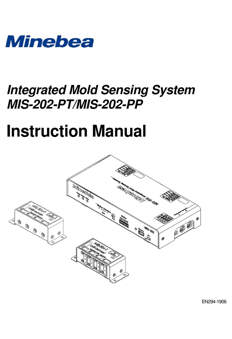
Minebea MIS-202-PT User manual

Integrated Mold Sensing System
MIS-202-PT/MIS-202-PP
Modbus Communication
Instruction Manual
EN294-1923


I
Introduction
Thank you for purchasing the MIS-202-PT/MIS-202-PP Integrated Mold Sensing System. This
instruction manual describes how to operate the device, as well as noteworthy points. Note that
handling or operating the device incorrectly may result in malfunctions. Read this manual thoroughly
before use for safety and optimal results.
Pictograms and Conventions Used in This Manual
This manual uses the following pictograms to indicate actions to avoid at all times, aspects requiring
caution, and other noteworthy matters. Be sure to read the descriptions provided alongside these
pictograms.
WARNING
This indicates circumstances in which incorrect handling may result in death or serious injury to users.
Avoid the actions described here at all times.
CAUTION
This indicates circumstances in which incorrect handling may result in injury to users or damage to
property.
This indicates operating or procedural precautions or restrictions.
Always read the details included here to avoid malfunctioning.
Positioning of This Document
This instruction manual describes how to connect and use the Modbus interface of the MIS-202-PT/PP.
For information on other product functions, basic handling instructions, and precautions, refer to the
MIS-202 manual.
MIS-202-PT/PP Instruction Manual (DRW No. EN294-1906)
For details of external equipment such as PLCs and gateways, please refer to the corresponding
equipment instruction manuals.

II
Revision History
Date
Manual No.
Revision reason (details)
June
2020
DRW. No.
EN294-1923
First edition FW Ver.1.100, APP Ver.1.000

III
Contents
INTRODUCTION......................................................................................................................................................I
PICTOGRAMS AND CONVENTIONS USED IN THIS MANUAL ...........................................................................I
POSITIONING OF THIS DOCUMENT.....................................................................................................................I
REVISION HISTORY...............................................................................................................................................II
CONTENTS............................................................................................................................................................III
1. OVERVIEW......................................................................................................................................................1
1-1. Features ...............................................................................................................................................1
2. PART NAMES AND FUNCTIONS...................................................................................................................1
2-1. Front panel ...........................................................................................................................................1
3. EQUIPMENT WIRING .....................................................................................................................................2
3-1. Communication connector pin configuration........................................................................................2
3-2. Connection Method ..............................................................................................................................2
4. MODBUS COMMUNICATION SETTINGS......................................................................................................3
4-1. Setup Screen........................................................................................................................................3
4-2. Modbus Settings...................................................................................................................................4
5. COMMUNICATION PACKETS........................................................................................................................5
5-1. Available Function Codes.....................................................................................................................5
5-2. Operation Example: Fetching 2 Bytes of Data.....................................................................................6
5-3. Operation Example: Fetching 4 Bytes of Data.....................................................................................6
5-4. Operation Example: Fetching at Least 8 Bytes of Data .......................................................................7
5-5. Error Response ....................................................................................................................................7
5-6. CRC Calculation...................................................................................................................................7
6. ADDRESS LIST...............................................................................................................................................8
6-1. Reading Control I/O Status (Read Coils) .............................................................................................8
6-2. Reading Alarm/Error Status (Read Discrete Inputs) ............................................................................8
6-3. Reading Shot Count and Time (Read Input Register)..........................................................................8
6-4. Reading Measurement (Read Input Register) .....................................................................................9
6-5. Reading Amplifier Version Information and Configuration (Read Holding Register)..........................10
6-6. Reading Common Settings (Holding Register) ..................................................................................11
6-7. Modbus Communication Specifications .............................................................................................11

1
1.Overview
The MIS-202-PT/PP features an RS-485 interface, allowing measurements and settings to be read out
using the Modbus standard communication protocol. It can be used when measurements are uploaded to a
factory network via an external device such as a commercially-available PLC or gateway.
* Modbus is a registered trademark of Modicon.
1-1. Features
(1) The communication physical layer uses RS-485, which offers excellent noise resistance and is not
affected by cable length.
(2) It allows programless communication with devices that support Modbus communication. This is
performed using mapped memory, which eliminates the need to create communication protocol
programs.
(3) Communication generally consists of characteristic data in the form of numerical data for each molding
cycle and amplifier setting details, and these can be read out remotely to maintain quality and monitor
aspects such as operation status.
2.Part Names and Functions
2-1. Front panel
(1) Status LEDs
Indicate the equipment status.
The Power LED illuminates when the power is on, the Alarm LED illuminates when an alarm occurs,
and the Error LED illuminates when an amplifier error occurs.
(2) Link LEDs
Indicate the individual communication sending/receiving status. The LEDs flash when communication
is in progress.
Modbus: Communication with external devices (left-hand LED: receiving; right-hand LED: sending)
Extension: Master/slave communication when channels are expanded (left-hand LED: receiving;
right-hand LED: sending)
(3) F.G. Terminal (For Modbus Communication Cable)
Used to connect the shield on the Modbus communication cable to reduce noise effects. This should
be used as necessary depending on the communication conditions with connected external devices.
An F.G. terminal is also provided on the Modbus connector, allowing either to be used.
(4) Modbus Connector
Connector for Modbus communication with external network devices such as a gateway.
(2) Link LEDs
(4) Modbus connector
(1) Status LEDs
(3) F.G. terminal

2
3.Equipment Wiring
3-1. Communication connector pin configuration
The Modbus plug provided can be used for connecting to network devices such as a gateway. Using the
FA409-555 Modbus cable sold separately makes wiring easier.
No.
Signal
Description
1
S.G.
Signal ground
2
RX-
Differential input (-)
3
RX+
Differential input (+)
4
TX-
Differential output (−)
5
TX+
Differential output (+)
6
F.G.
Frame ground
Always turn off the power before wiring. Clamp the cable at a distance of approximately 1 m from the
amplifier to prevent the connector from being pulled out by the weight of the cable.
3-2. Connection Method
Connect the wires to the plug as follows:
(1) Strip the sheathing on ends of the wires to a length of 7 mm.
(2) Using a flathead precision screwdriver, turn the screw counter-clockwise to open the wire insertion
hole.
(3) Insert the wire into the wire insertion hole.
(4) Turn the screw clockwise using the screwdriver to clamp the wire insertion hole.
Always turn off the power before connecting wires.
The wiring for connections to the terminal board should be AWG 28 to 16 (stranded wire).
Strip the wire sheathing 7 mm ±1 mm from the end.
The terminal board tightening torque is 0.22 N・m to 0.25 N・m.
Modbus plug provided
6
1
(1)
(2)
(3)
(4)

3
4.Modbus Communication Settings
Connect a PC to the amplifier and set up using the MIS-Anest measuring application.
4-1. Setup Screen
Click the [Change] icon, then open the [Analog Output/Modbus] tab on the [Change conditions] screen.
The [Change] button is disabled unless [Stop loading data] is clicked to stop waveform data from
being acquired.

4
4-2. Modbus Settings
Set the communication specifications to suit the connected external device.
Setting
Description
Default
RS-485
communication
address
01 to 31
01
Data bit length
8 bit (fixed)
–
Parity bit
[None], [Even], [Odd]
None
Stop bit
[1 bit], [2 bit]
1 bit
Baud rate
1200 bps, 2400 bps, 4800 bps, 9600 bps, 19200 bps,
38400 bps, 57600 bps, 76800 bps, 115200 bps,
230400 bps
115200 bps
Terminator
None
–
The amplifier terminal resistance is built in.

5
5.Communication Packets
5-1. Available Function Codes
The MIS-202 uses the following Modbus protocol function codes. Only reading from the host to the
MIS-202 is possible, and writing is not supported.
Read Discrete Inputs (0x02)
Read Coils Status (0x01)
Read Input Register (0x04)
Read Holding Registers (0x03)
Reference source: http://modbus.org/docs/Modbus_Application_Protocol_V1_1b3.pdf

6
5-2. Operation Example: Fetching 2 Bytes of Data
Fetch the last two bytes of the interval time.
Request (external device → MIS-202)
Requests reading out of data for one address from Input Register address No. 8.
Field
Name
RS485
Address
Function
Code
Starting
Address
(Hi)
Starting
Address
(Lo)
Address
Size
(Hi)
Address
Size
(Lo)
CRC
Lo
CRC
Hi
(Hex)
01
03
00
8
00
01
05
C8
Response (MIS-202 → external device)
Response when interval time is 255 seconds.
Field
Name
RS485
Address
Function
Code
Byte
Count
Data0
(Hi)
Data0
(Lo)
CRC
Lo
CRC
Hi
(Hex)
01
03
02
00
ff
f8
04
Data
255 seconds
5-3. Operation Example: Fetching 4 Bytes of Data
Fetch the sampling interval setting.
Request (external device → MIS-202)
Requests reading out of data for two addresses from Holding Register address No. 50004.
Response when the sampling interval is set to 3 (5 ms).
Field
Name
RS485
Address
Function
Code
Starting
Address
(Hi)
Starting
Address
(Lo)
Address
Size
(Hi)
Address
Size
(Lo)
CRC
Lo
CRC
Hi
(Hex)
01
03
c3
52
00
2
59
5e
Response (MIS-202 → external device)
Field
Name
RS485
Address
Function
Code
Byte
Count
Data1
(Hi)
Data1
(Lo)
Data0
(Hi)
Data0
(Lo)
CRC
Lo
CRC
Hi
(Hex)
01
03
04
00
03
00
00
0a
33
Data
0003h
0000h

7
5-4. Operation Example: Fetching at Least 8 Bytes of Data
Fetch the current time data (8 bytes).
Request (external device → MIS-202)
Requests reading out of data for four addresses (8 bytes) from Input Register address No. 0000.
Field
Name
RS485
Address
Function
Code
Starting
Address
(Hi)
Starting
Address
(Lo)
Address
Size
(Hi)
Address
Size
(Lo)
CRC
Lo
CRC
Hi
(Hex)
01
03
00
00
00
04
44
09
Response (MIS-202 → external device)
Response when the present time and date is 23:06:10 February 3, 2021
Field
Name
RS485
Address
Function
Code
Byte
Count
Data1
(Hi)
Data1
(Lo)
Data0
(Hi)
Data0
(Lo)
(Hex)
01
03
08
02
03
14
15
Data
February 3
2021
Data4
(Hi)
Data3
(Lo)
Data2
(Hi)
Data2
(Lo)
CRC
Lo
CRC
Hi
06
0a
02
03
48
32
6 minutes 10
seconds
23 hours
5-5. Error Response
The following error is returned when data with an invalid format is received at the MIS-202.
Field
Name
RS485
Address
Function
Code +
0x80
Exception
Code
CRC
Lo
CRC
Hi
(Hex)
01
8x
02
xx
xx
Exception Code
Remarks
01
Invalid function
02
Invalid data address
03
Invalid data
5-6. CRC Calculation
The CRC (Cyclical Redundancy Checking) field consists of two bytes, and includes a 16-bit binary value.
The CRC value is calculated by the sending device with CRC appended to the message. The receiving
device recalculates CRC while receiving the message, and compares the calculated value against the
value actually received in the CRC field. An error occurs if the two values are not equal. For details, refer
to “6.2.2 CRC Generation” in the “MODBUS over serial line specification and implementation guide”
issued by Modbus.org.
Example message calculation
Addr
Func
Data
Count
Data
Data
Data
CRC
Lo*
CRC
Hi*
01
03
00
00
00
04
44
09
* When CRC is included in a message, the bytes before and after it must be switched as shown above.
Reference: https://crccalc.com/

8
6.Address List
6-1. Reading Control I/O Status (Read Coils)
Reads out the MIS-202 control input signal status from the host.
Address
Function
type/Code
Date
size
Function Name
Description
0
Coil
01
1 bit
START input status
0: START, 1: Normal
Held for approx. 1 sec after start
1
1 bit
ALARM RESET input status
0: RESET, 1: H
Held for approx. 1 sec after reset
2
1 bit
ALARM STOP input status
0: Disabled, 1: Enabled
6-2. Reading Alarm/Error Status (Read Discrete Inputs)
Reads out the MIS-202 alarm and error status from the host.
Address
Function
type/Code
Date
size
Function Name
Description
0
to
31
Discrete
Inputs
02
1 bit
Channel 1 to 32 alarms
0: OK, 1: NG, corresponding to detection
output
(Detection result output for each channel)
32
1 bit
Shot alarm (together with
“Alarm” LED)
0: OK, 1: NG, corresponding to control I/O
alarm output
(Detection result output for each shot)
33
1 bit
Error (together with “Error”
LED)
0: No error, 1: Error
6-3. Reading Shot Count and Time (Read Input Register)
Reads out the MIS-202 shot counter and time from the host.
Address
Function
type/Code
Date
size
Function Name
Description
0
Input
Register
04
2 bytes
Total shot count (LSB)
Corresponds to last 2 bytes.
1
2 bytes
Total shot count (MSB)
Corresponds to first 2 bytes.
2
2 bytes
NG shot count (LSB)
Corresponds to last 2 bytes.
3
2 bytes
NG shot count (MSB)
Corresponds to first 2 bytes.
4
4 bytes
Measurement start time
stamp
(20YYMMDD)
Example: September 25, 2021
20YYMMDD = 20210925
6
4 bytes
Measurement start time
stamp
(00hhmmss)
Example: 15:23:10
00Hhmmss = 00152310
8
2 bytes
Interval time (LSB)
Corresponds to last 2 bytes.
9
2 bytes
Interval time (MSB)
Corresponds to first 2 bytes.

9
6-4. Reading Measurement (Read Input Register)
Reads out information related to alarms set in the MIS-202 from the host.
Address
Function
type/Code
Ch
Date
size
Function Name
Description
18
Input
Register
04
Ch1
4 bytes
Shot alarm
Detection result output for
each shot
(previously completed shot)
0: OK/1: NG
20
4 bytes
Peak
Units: [MPa][°C]
22
4 bytes
Time to peak
Unit: [sec]
24
4 bytes
Integral to peak (LSB)
Units: [MPa・sec][°C・sec]
Corresponds to last 4 bytes.
26
4 bytes
Integral to peak (MSB)
Units: [MPa・sec][°C・sec]
Corresponds to first 4 bytes.
28
4 bytes
Value after t seconds
Units: [MPa][°C]
30
4 bytes
Integral (LSB)
Units: [MPa・sec][°C・sec]
Corresponds to last 4 bytes.
32
4 bytes
Integral (MSB)
Units: [MPa・sec][°C・sec]
Corresponds to first 4 bytes.
34
4 bytes
Peak over eject (pressure)
Unit: [MPa]
36
4 bytes
Reserved
38
4 bytes
Reserved
40
4 bytes
Reserved
42
4 bytes
Reserved
44
4 bytes
Alarm category
M1, M2, M3, IT from LSB side
Measurements for other channels can be read in the same way using the following addresses.
Channel
Address
Channel
Address
Channel
Address
Channel
Address
Ch1
18 to 44
Ch9
242 to 268
Ch17
466 to 492
Ch25
690 to 716
Ch2
46 to 72
Ch10
270 to 296
Ch18
494 to 520
Ch26
718 to 744
Ch3
74 to 100
Ch11
298 to 324
Ch19
522 to 548
Ch27
746 to 772
Ch4
102 to 128
Ch12
326 to 252
Ch20
550 to 576
Ch28
774 to 800
Ch5
130 to 156
Ch13
254 to 380
Ch21
578 to 604
Ch29
802 to 828
Ch6
158 to 184
Ch14
382 to 408
Ch22
606 to 632
Ch30
830 to 856
Ch7
186 to 212
Ch15
410 to 436
Ch23
634 to 660
Ch31
858 to 884
Ch8
214 to 240
Ch16
438 to 464
Ch24
662 to 688
Ch32
886 to 912
The alarm categories are identified by the following codes.
Code
Description
M1
Alarm system 1 detection is “NG” (area, peak, point, or time to peak)
M2
Alarm system 2 detection is “NG” (peak, point, or time to peak)
M3
Alarm system 3 detection is “NG” (area, peak, point, or time to peak)
IT
Integral value related detection is “NG” (integral or integral to peak)

10
6-5. Reading Amplifier Version Information and Configuration (Read Holding
Register)
Reads out the MIS-202 version information and amplifier configuration (pressure or temperature) from
the host.
Address
Function
type/Code
Date
size
Function Name
Description
0
Holding
Register 03
4 bytes
Current date
Date retained by the amplifier
[yyyymmdd]
2
4 bytes
Current time
Time retained by the amplifier
[00hhmmss]
4
4 bytes
MASTER: Ch1 to Ch4 sensor type
0: None, 1: Pressure,
2: Temperature, 3: Other
6
4 bytes
MASTER: Ch5 to Ch8 sensor type
8
4 bytes
MASTER: FW version
Example: 1234h = Ver.1.234
10
4 bytes
MASTER: Boot loader version
12
4 bytes
SLAVE1: Ch1 to Ch4 sensor type
0: None, 1: Pressure,
2: Temperature, 3: Other
14
4 bytes
SLAVE1: Ch5 to Ch8 sensor type
16
4 bytes
SLAVE1: FW version
Example: 1234h = Ver.1.234
18
4 bytes
SLAVE1: Boot loader version
20
4 bytes
SLAVE2: Ch1 to Ch4 sensor type
0: None, 1: Pressure,
2: Temperature, 3: Other
22
4 bytes
SLAVE2: Ch5 to Ch8 sensor type
24
4 bytes
SLAVE2: FW version
Example: 1234h = Ver.1.234
26
4 bytes
SLAVE2: Boot loader version
28
4 bytes
SLAVE3: Ch1 to Ch4 sensor type
0: None, 1: Pressure,
2: Temperature, 3: Other
30
4 bytes
SLAVE3: Ch5 to Ch8 sensor type
32
4 bytes
SLAVE3: FW version
Example: 1234h = Ver.1.234
34
4 bytes
SLAVE3: Boot loader version

11
6-6. Reading Common Settings (Holding Register)
Reads out the MIS-202 common settings from the host.
Address
Function
type/Code
Date
size
Function Name
Description
50000
Holding
Register
03
4 bytes
Reserved
50002
4 bytes
Sampling interval
0: 0.5 ms, 1: 1 ms, 2: 2 ms, 3: 5 ms
4: 10 ms, 5: 20 ms, 6: 50 ms
50004
4 bytes
Span
1 to 1800 [seconds]
50006
4 bytes
Start trigger signal switching
0: Falling, 1: Rising, 2: None
50008
4 bytes
Start trigger delay
0 to 250 × 0.1 [seconds]
50010
4 bytes
Eject measurement start time
0 to 180,000 × 0.01 [seconds]
50012
4 bytes
Eject measurement end time
0 to 180,000 × 0.01 [seconds]
50014
4 bytes
Reserved
50016
4 bytes
Reserved
50018
4 bytes
Measurement mode
0: Trigger mode, 1: Continuous mode
50020
4 bytes
Reserved
50022
4 bytes
Analog Output Settings
0: Disabled, 1: Enabled
50024
4 bytes
Enabled channel selection
Bit[31:0] = CH[32:1]
50026
4 bytes
Start signal interrupt
0: Disabled (Ignored during
measurement)
1: Enabled (Received during
measurement)
50028
4 bytes
Reserved
50030
4 bytes
Modbus communication settings
See separate table.
50032
4 bytes
Modbus address
1 to 31
The Modbus communication settings are defined as follows.
Digit
Setting
Description
First
digit
Parity
0: None, 1: Even, 2: Odd
Second
digit
Stop bit
0: 1 bit, 1: 2 bits
Third
digit
Baud rate
0: 1200 bps, 1: 2400 bps, 2: 4800 bps, 3: 9600 bps, 4: 19200 bps,
5: 38400 bps, 6: 57600 bps, 7: 76800 bps, 8: 115200 bps, 9: 230400 bps
Fourth
digit
Terminator
2: None (Fixed)
6-7. Modbus Communication Specifications
Specifications
Details
Communication
standard
RS-485
Protocol
Modbus RTU compliant
Sync mode
Asynchronous
Transmission mode
4-wire full-duplex
Baud rate
1200 bps, 2400 bps, 4800 bps, 9600 bps, 19200 bps, 38400 bps,
57600 bps, 76800 bps, 115200 bps, 230400 bps
Data bit length
8 bit (fixed)
Parity bit
[None], [Even], [Odd]
Stop bit
[1 bit], [2 bit]
Terminator
None
Valid address
01 to 31 (00: Does not support broadcast)
Terminal resistance
Built in
Status LEDs
Link LED (RX, TX)
Other manuals for MIS-202-PT
1
This manual suits for next models
1
Table of contents
Other Minebea Measuring Instrument manuals

Minebea
Minebea CSD-701C User manual

Minebea
Minebea CSD-892B-73 User manual

Minebea
Minebea MIS-202-PT User manual

Minebea
Minebea CSD-904-EX User manual

Minebea
Minebea CSD-801 User manual

Minebea
Minebea CSD-709 User manual

Minebea
Minebea CSD-903-73 User manual

Minebea
Minebea CSD-892B-74 User manual

Minebea
Minebea CSD-891B User manual

Minebea
Minebea TMD-100 User manual