Solar MD SS4143-11 User manual

INSTALLATION MANUAL
SS4143-11
Advanced Lithium-Ion battery
0

Introduction 2
Product Description 2
Product Specifications 3
Errors or Inaccuracies 3
Copyrights 3
Safety Information 3
⚠Warnings ⚠Cautions 3
Specification 4
Mechanical installation 5
Installing cover plates 6
Electrical installation 9
Switching the battery ON 11
Multicolor multipurpose button 12
Button function 12
Button indication 18
Firmware 19
How to Update 19
Communication 20
Pinout 21
Monitoring and control 22
CANBUS connection. 23
CANBUS warnings and errors 25
BMS Warnings and Errors 26
Troubleshooting Warnings / Errors 27
Warning register 29
Error register 32
Maximum charging / discharging voltages for non supported devices. 36
Annex A: BMX-EX Inverter / Charger control and cluster operation 37-53
1

Introduction
This manual is intended to provide assistance to an installer for the installation and
commissioning of the range of Solar MD Lithium Ion phosphate (LiFePO4) energy storage
solutions.
Product Description
The SS4143-11 battery solution is available in one standard size and can be paralleled to
meet most residential applications. The rated voltage is 51.2V nominal (to suit 48V systems).
Larger systems are provided by Solar MD based on specific project requirements.
WARNING: Read the entire document before installing or using the Solar MD battery. Failure
to comply with the instructions or warnings in this document could result in electrical shock or
serious injury that can result in death or damage to the product that can render the SS4143
Solar MD battery inoperable.
2
Product Specifications
All SS4143-11 specifications & descriptions contained in this document are verified to
be accurate at the time of printing. Solar MD reserves the right to make any product
revisions & improvements at any time.
Errors or Inaccuracies
To communicate any inaccuracies, omissions or to provide general feedback regarding this
manual, send an email to [email protected]
Copyrights
All information in this document is subject to the copyright of Solar MD (Pty) Ltd. Additional
information is available upon request.
Safety Information
This manual contains important instructions and warnings that must be followed when using
SS4143-11.
Read all instructions before installing and using the SS4143-11.
Warnings Cautions
● Use SS4143-11 only as instructed.
● For communication and other information please read the BMS manual.
● Do not attempt to disassemble, repair, modify, or tamper with this battery unit.
● Do not insert foreign objects into any part of the battery unit.
● Avoid exposure to any moisture.
● Do not expose to extreme temperatures.
● Do not drill any holes into the box.
● Use only an approved Solar MD installer to install this product.
Failure to comply will void the warranty
3

Specification
Solar MD 14.3kWh SS4143-11 specification
Battery type
Lithium Iron
Phosphate
Scalability
Yes
Battery module
SS4143
Communication
CANBUS 500kbps / CAN
2.0B
Rated battery capacity
14336 Wh
Can BUS termination
Single 120 Ohm
Output power
Max 10 kW
Canbus ID range:
256 - 499
Usable battery energy @
0.3℃
13.00 kWh
Protection method
Cell level: uv / ov / oc
Position: x / y / x
Acceleration: x / y / z
Temperature: ot / ut
Nominal voltage
51.2V
Protection phy
Mechanical relay NO
Rated Current (Ampere)
200A
C Rating
0.71C
Number of battery modules
1 module
Com (CANBUS ) isolation
Yes 1.5kV
Weight
118kg
Transportation protection
Yes
Operating voltage
44.8V - 55.6Vdc
Indicator
Led, programmable
Communication
CANBUS
Addition IO
3 GPO
Dimensions of SS4143:
h/w/d (mm)
650/600
/210
Cell balancing
Passive balancing
Net Weight of SS4143
118 kg
Counters
Cycle counters and SoH
Battery cycle life [+25 ℃]
> 4000
AUX power output
5V 1A max
Charging efficiency
99%
Storage duration
6 months@+25℃
Operating temperature
-5℃~+50℃
Safety standards
compliance
IEC 62619/UN 38.3/UL1642
Transport
UN3480 & UN38.3
Cell Certificate
TUV / CE / RCM / UL1642
4
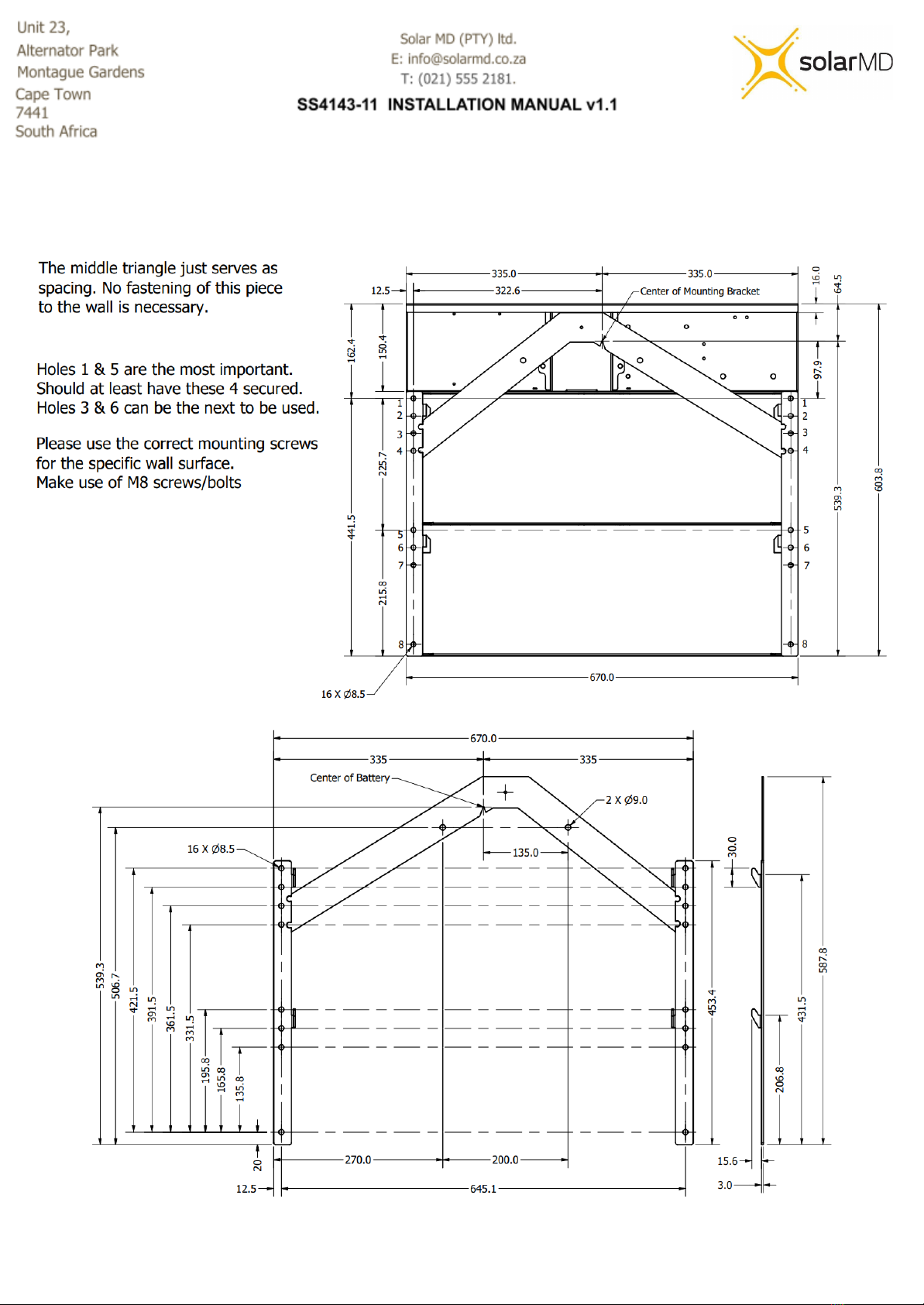
Mechanical installation
5

Installing top cover plate
Figure 3a: Top cover installation single or multiple batteries in line
6
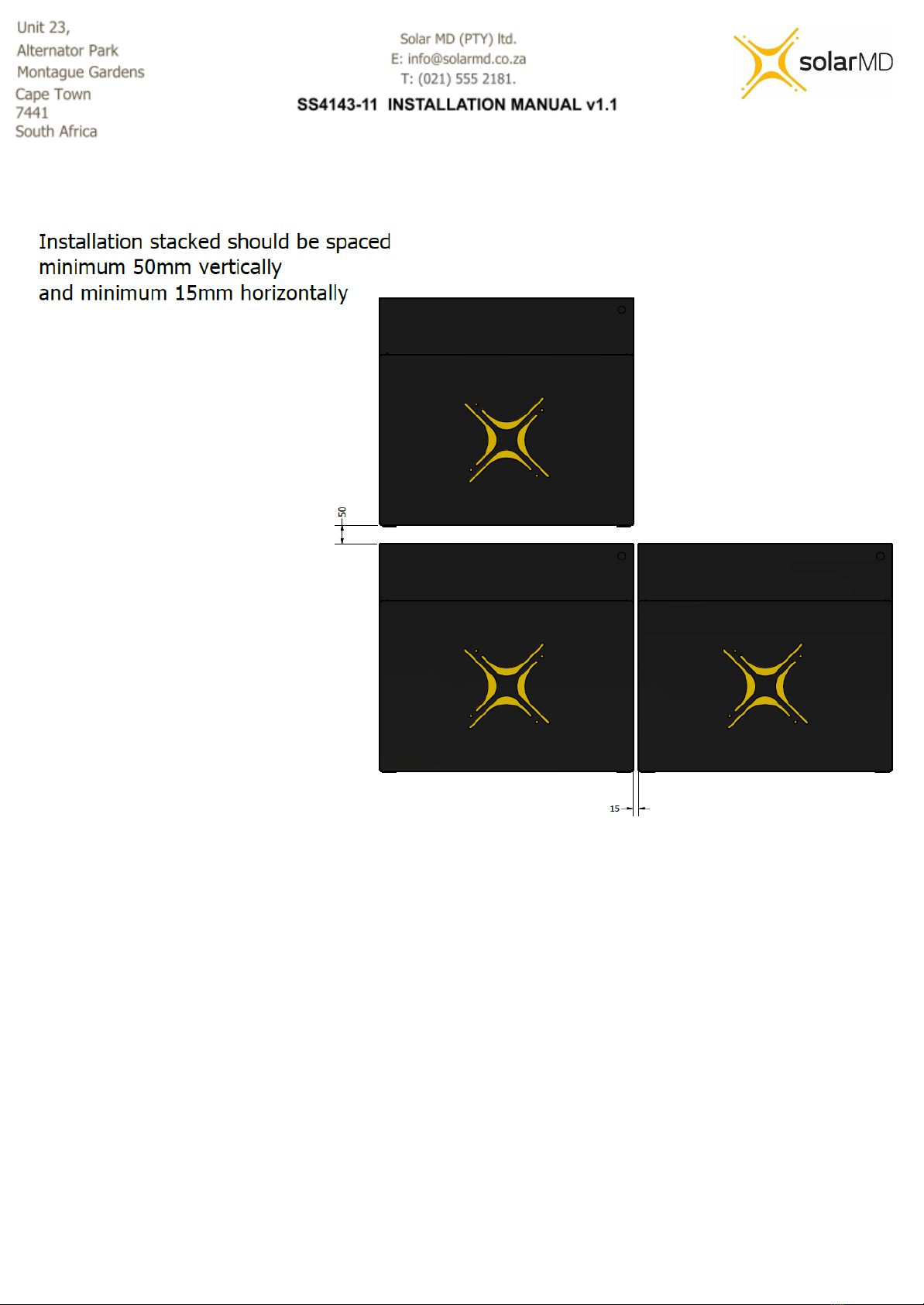
Figure 3b: Battery spacing - installation single or multiple batteries in line
7

Figure 3c: Battery feet - installation of battery feet
8
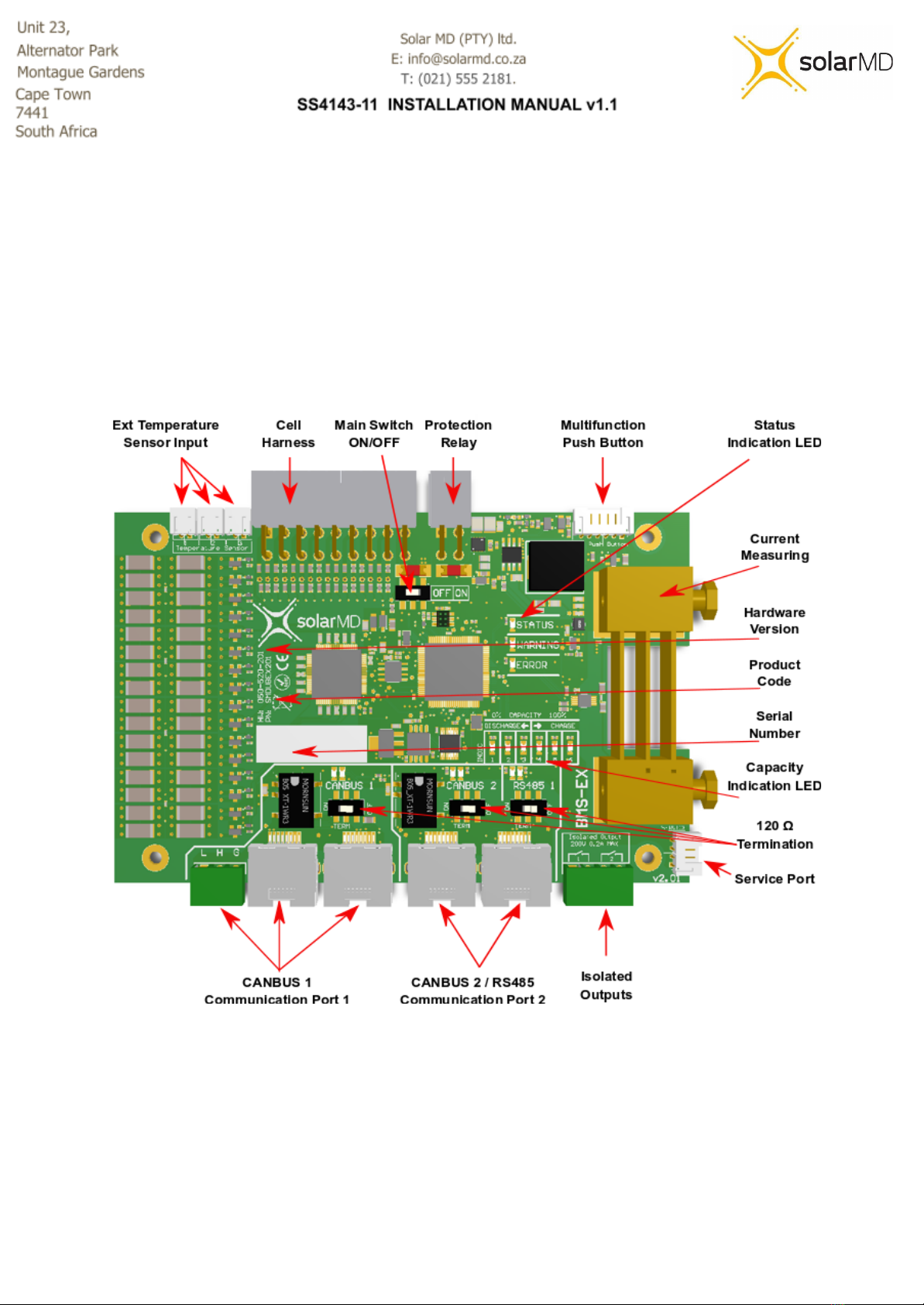
Electrical installation
Step 1. Before connecting anything be sure that the battery ON/OFF switch is at OFF
position. (figure 4)
Figure 4: BMS board component locations
9

Connecting Inverters/chargers/UPS to the battery unit while it is ON can cause big sparks due
to capacitors inside the connected device. This can be harmful to people.
Connecting the main battery terminal must be with the correct size cable
based on the rated current of the battery and the charger/inverter in case it’s lower.
Figure 5: Connection terminals
Step 2. Connect the negative cable to the battery negative busbar and positive cable to the
battery positive busbar as shown in figure 5.
10
Switching the Battery ON
Step 1. Make sure all DC cables are tightened according to specifications.
Step 2. If the battery operates in parallel with other energy sources, make sure that the
difference between battery voltage and DC bus is not more than 2.5V. If greater than 2.5V
please charge or discharge the other source accordingly until the voltage difference is in a
safe range under 2.5V.
Caution! A hot connection with difference in voltage can cause very high
equalization current which can burn the fuses of the battery!
Caution! Measure the voltage of the battery before connecting the DC
cables.
Step 3. Turn the BMS board ON/OFF switch to the ON position (figure 4).
Step 4. Connect Multipurpose button if not connected to the BMS board connector (figure 4).
Step 5. Hold the multi purpose button until the light comes on.
Warning! If the battery does not switch the main protection contactor ON in
7 sec, please check the BMS board indication LED for faults. See section BMS
Error and Warnings.
11

Multicolor multipurpose button
Figure 6 : Multicolor / Multipurpose button.
Button functions
The main functions of MFB (Multi Function Button) are:
- Switching Battery On/Off
- Representing various states of the battery with its built-in LED.
- Accessing quick function list
- Parameter Menu
1. Switching battery ON/OFF
- Start by putting the ON/OFF micro switch on the BMS into the ON position.
- To switch the battery ON, simply push and press the button until boards get illuminated.
- To switch the battery OFF, press and hold the MFB for 10 sec until the board switches all
lights off.
12

2. LED States
The MFB is equipped with an LED bezel which can be configured to show different types of
battery information. Under normal battery conditions it can be configured to display battery
capacity, Current flow direction (charge or discharge) or OFF. This setting will be overridden if
the battery is in warning mode or error mode. When in warning mode the LED will flash orange
and when in error mode the LED will flash red.
3. Accessing a quick function list.
MFB can execute 4 predefined functions. These functions are accessed by pressing and holding
the MFB. While holding, the Indication LEDs (see Figure 10 below) will start to illuminate from
left to right . The amount of illuminated LEDs represents the number of the function (1 - 6). To
activate a function, release the button when the desired function is selected, then the LEDs will
start blinking quickly for around 3 sec. While the LED is blinking, quickly press and release the
MFB to confirm the function activation. If no confirmation is triggered the operation will be
canceled. The available functions are:
- Function 1: Reserved
- Function 2: By selecting function 2 you can toggle between 3 Indication LEDs
functions:
- Show current flow and direction
- Show battery capacity
- LEDs off.
- Function 3: Reserved
- Function 4: Accessing Parameter Menu
- Function 5: Execute override ON for 120 seconds
- Function 6: Execute override OFF for 120 seconds
4. Parameter Menu
After entering the parameter menu from calling Function 4 you can change BMS parameters.
The Parameter Menu uses all 6 indication LEDs to represent a Parameter Number and 6 LEDs
from CANBUS1, CANBUS2, RS485 to represent a parameter value. The selected state between
13

parameter number and parameter value is represented by LEDs flashing e.g if Indication LEDs
are flashing the current menu state is Parameter number.
Changing Parameter number is done by a single quick press of MFB, to switch to value mode
press and hold MFB for more than 2 seconds, after that the value LEDs will start blinking quickly.
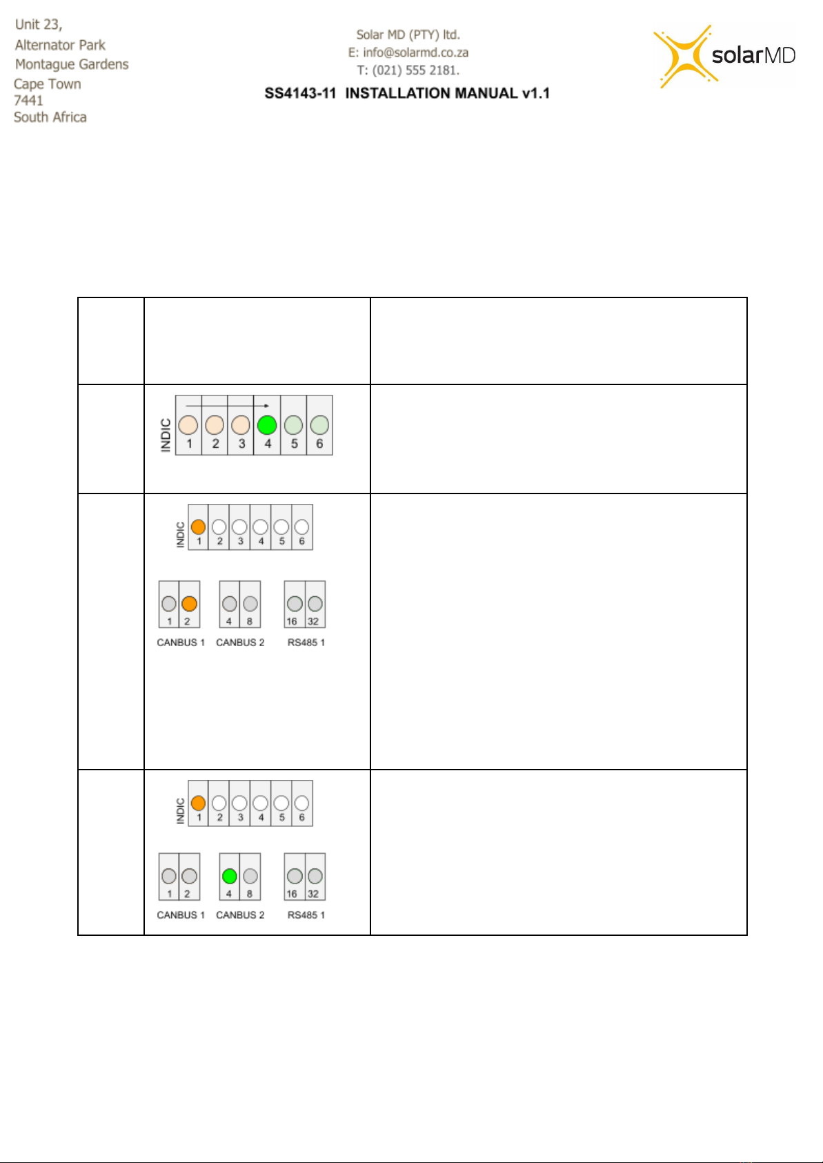
● Converting LEDs to values.
Group of LEDs can represent a single digit. These digits can be simply read by a simple
method of summing. Each LED in the group represents a number. LED 1 = 1, LED 2 = 2,
LED 3 =4, LED 4 = 8, LED 5 = 16 and LED 6 = 32.
Summing the values of the illuminated LEDs will give you the calculated number.
Example
Visual Representation
Description
1
Sum up all the LEDs that are illuminated to get the
represented value.
0 + 2 + 0 + 0 + 0 + 0
= 2
2
Sum up all the LEDs that are illuminated to get the
represented value.
1 + 0 + 0 + 8 + 16 + 0
= 25
14

Figure 7: LEDs on the BMS
Main menu navigation
Parameter
number
Parameter
Possible value
1
Reserved
2
Function of Indication LEDs
1. Show current flow and direction
2. Show battery capacity
3. LEDs off
3
Reserved
4
Enter Sub menu
(see below for more detail)
See table below for more info
5
Execute override OFF for 120 seconds
6
Execute override ON for 120 seconds
15

Sub menu navigation
Parameter
number
Parameter
Possible value
1
Operation mode
1. Test mode
2. Low voltage mode
3. Production mode
4. High voltage mode
2
Reserved
3
Inverter type
(Low voltage Mode)
1. None (Feature disabled)
2. SMA
3. Victron
4. Sunsynk
5. Goodwe
6. Growatt
4
Reset Cluster Nodes
1. None
2. Reset
5
Reserved
6
Reserved
16
Example: Navigating the sub menu to change BMS operation from Standalone mode to High
Voltage mode.
Visual Representation
Description
Step 1
- Press and hold until the 4th LED starts
blinking (the LEDs will blink sequentially from
left to right starting at LED 1).
- Long press the button to enter into the sub
menu.
Step 2
You are now in the Sub menu
- Quick press to navigate the sub menu until
the 1st indication LED is blinking to enter the
operation mode (parameter 1 of the sub
menu).
- Long press to enter into the operation mode
setting.
- The CANBUS 1, 2 and RS485 LEDs will now
start blinking, showing the current settings for
the specific parameter.
(it's currently showing Standalone mode)
Step 3
- Quick press to navigate to production high
voltage mode.
- Long press to save the setting.
- All done! Leave the button for 20 seconds or
long for it to go back to its home screen
17

Button indication
**Access to all features in future development
The Multipurpose button advanced indication functionality, allows the user to choose
between 5 different states. Mixed combinations are also allowed when a combination of
multiple batteries with BMS-EX are
used. The User can change the prefered stage by logging into their mypower24 Energy
Portal and going to the Battery Settings.
Illumination off
**For future development
When this state has been selected, the button serves as an on/off switch without illumination
(fixed colour).
Color based on capacity
When this state has been selected, the button shows static illumination in a color based on
the state of charge. From RED at 0% SoC (State of Charge) to GREEN at 100% state of
charge.
Color based on capacity with current direction based on
shading.
**For future development
When this state has been selected, the button shows flashing illumination in a color based
on the state of charge and flashing code based on the electrical current direction (charge /
discharge). From RED at 0% SoC (State of Charge) to GREEN at 100% state of charge.
The flashing code for charge goes through illumination interruption for 1 interval and slow
illumination into the color based on the SoC for 5 intervals. The flashing code for discharge
represents the opposite from charge - study color for 1 interval and slow loss of color
following illumination interruption. Solar MD users refer to both as charging / discharging
waves.
18

Fixed color with current direction based in shading
**For future development
When this state has been selected, the button shows illumination in a color based on the
user choice and flashing code based on the electrical current direction (charge / discharge).
The flashing code for charge goes through illumination interruption for 1 interval and slow
illumination for 5 intervals. The flashing code for discharge represents the opposite from
charge - study color for 1 interval and slow loss of color following illumination interruption.
Solar MD users refer to both as charging / discharging waves.
Firmware
BMS EX can store multiple firmware versions. Upon startup the bootloader will start the latest
version available.
How to Update
Logger V2 can update the firmware of a connected and communicating BMS via CANBUS. The
logger stores available BMS-Ex firmwares locally and can send it to the BMS as requested.
Firmware Update Settings
-Refresh Loaded Firmware info BMS: Press “Refresh”to see the latest BMS firmware
version that has been sent from the logger to the BMS.
-Check Available Updates: Press the “Check”button to see the latest BMS firmware
version available.
-Upload Available Firmware to BMS: If the BMS firmware version is lower than the latest
available firmware version then type in the firmware version you would like to upload in the
space provided and click “upload”.
- Write Loaded Firmware: Once the firmware has been fully uploaded from the logger to
the BMS (progress bar should show 100%) click the “write” button. This will start the two
step installation process on the BMS.
- The BMS will first verify the uploaded firmware, during this process the indication
LEDs on the BMS will flash slowly from left to right.
- The second part is installing the firmware, during this process the indication LEDs
on the BMS will flash fast from right to left. Once successfully installed the BMS will
restart. Verification of a successful update can be seen on the MyPower24 portal.
19
Table of contents
Other Solar MD Camera Accessories manuals


