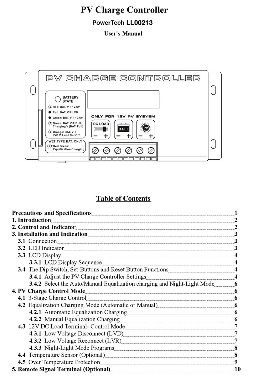
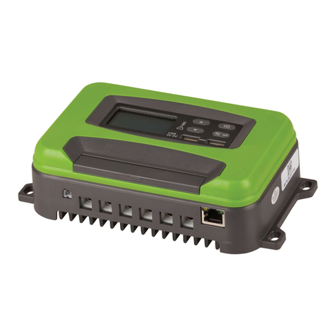
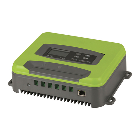
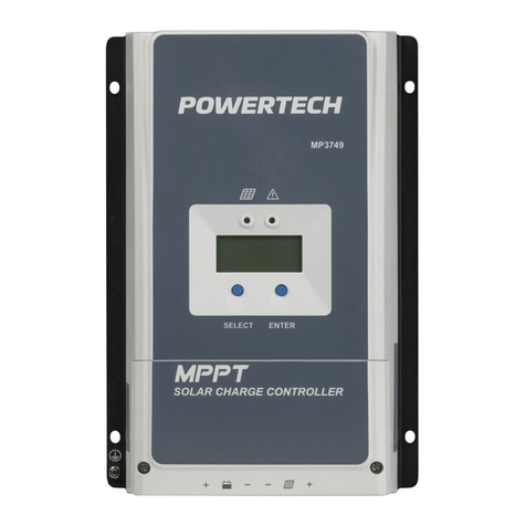
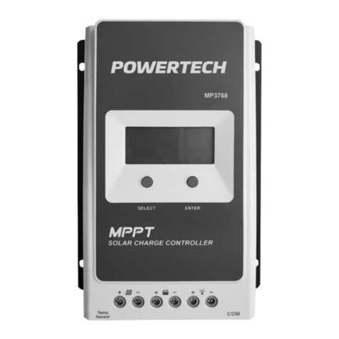
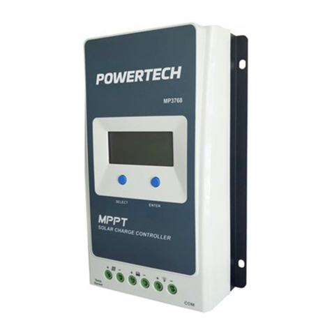
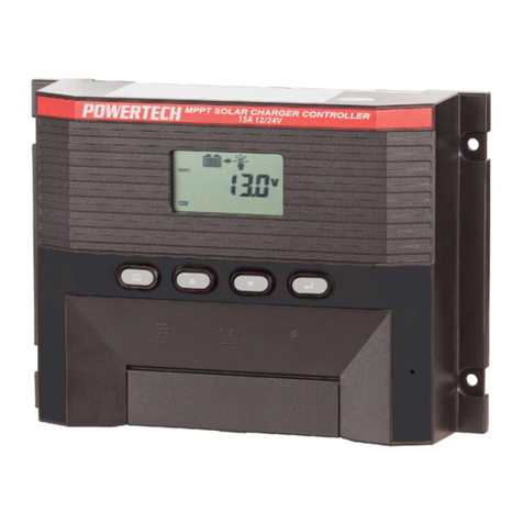
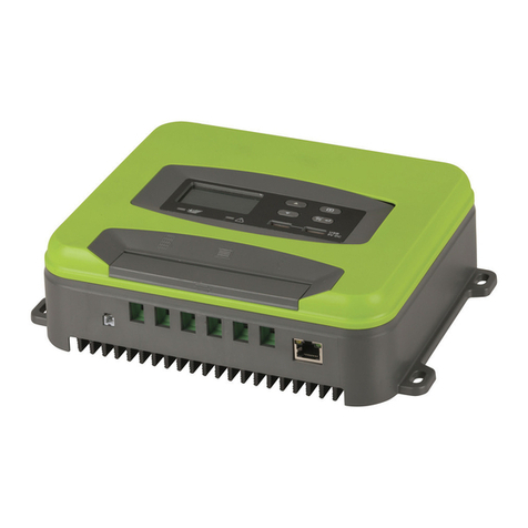
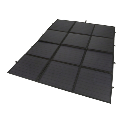
PowerTech MP3741 User manual

Page 1
MP3741 MPPT Solar Charge Controller
User Manual

Page 2
Important Safety Instructions
Please keep this manual for future reference. This manual contains all
instructions of safety, installation and operation for MP3741 Maximum Power
Point Tracking (MPPT) controller (referred in this manual as "the controller").
General Safety Information:
• Carefully read all the instructions and warnings in the manual before
installation.
• No user serviceable component inside controller. DO NOT disassemble or
attempt to repair the controller.
• The controller must be mounted indoors, or outdoors in a waterproof
enclosure. Prevent exposure to the elements and do not allow water to enter
the controller.
• Install the controller in a well-ventilated place; the controller’s heat sink may
become very hot during operation.
• Always Install appropriate external fuses/breakers.
• Ensure all connections to Solar panels and batteries are disconnected or
otherwise disabled before making or altering bare-wire connections to
controller.
• Take particular care that all power connections are tight and likely to remain
so to avoid excessive heating from a loose connection.

Page 3
Contents
1 General Information ............................................................................... 4
1.1 Overview........................................................................................ 4
1.2 General Appearance and Connections ............................................ 5
1.3 Available Accessories ..................................................................... 6
1.4 Maximum Power Point Tracking Technology Details ........................ 6
1.5 Battery Charging Stage .................................................................. 8
2 Installation Instructions……………………………………………………...…10
2.1 General Installation Notes…………………………………………...……10
2.2 Solar Array Requirements………………………..……………………….11
2.3 Wire Size ..................................................................................... ..11
2.4 Mounting…………………………………………………………..………..12
3 Operation ............................................................................................. ..13
3.1 Button Function ............................................................................ ..14
3.2 LCD Display ................................................................................. ..14
3.3 Parameters setting ....................................................................... ..16
3.4 Battery type.................................................................................. ..19
4 Protection systems, Troubleshooting and Maintenance ..................... ..20
4.1 Protection .................................................................................... ..20
4.2 Troubleshooting ........................................................................... ..22
4.3 Maintenance ................................................................................ ..23
5 Technical Specifications ...................................................................... ..24
Appendix 1 Conversion Efficiency Curves .................................................. ..25
Appendix 2 Dimensions............................................................................. ..26
Appendix 3. How to set battery parameters via WiFi APP ........................... ..27
Appendix 4. Solar Control Monitor for MP3741
(RS-485/USB) using USB cable adaptor .................................................... ..39

Page 4
1. General Information
1.1 Overview
With the MPPT control algorithm, the MP3741 can quickly and accurately
calculate the best maximum power point (MPP) of solar arrays, in order to
extract the maximum amount of charge current from the solar energy available.
This gives a considerable improvement over simpler PWM types, plus the solar
voltage can be much higher than the battery voltage.
There is a dual display function: The inbuilt LCD panel and remote meter (not
included). With Modbus communication protocol interface, users can control the
MP3741 via the Internet from any location with online access.
Features:
• Automatic current limit function of Solar input power, preventing overload.
• Wide MPPT operating voltage range.
• 12/24VDC automatic battery voltage detection.
• LCD panel display dynamically displays operating data and working
conditions.
• Multiple load control modes: Manual mode, Light ON/OFF, Light by Timer and
test mode.
• 3 preprogramed Lead-Acid battery options: Sealed, Gel, Flooded. Others can
be installed via external software (interface hardware required).
• Battery temperature compensation function (requires Remote Temperature
Sensor, not included).
• Real-time energy statistics function.
• RS-485 communication bus interface and Modbus communication protocol,
allow it to meet various remote communication requirements.
• Supports software upgrades.

Page 5
1.2 General Appearance and Connections
Figure 1-1 MP3741 Connections
Item
Name
Item
Name
①
Mounting hole (5mm)
⑥
Load Terminals
②
Select Button
⑦
RS-485 Port **
③
Remote Temperature
Sensor Socket *
⑧
Enter Button
④
PV (Solar) Power Input
Terminals
⑨
LCD Display
⑤
Battery Terminals
Explanations:
* Connection for an RTS (Remote Temperature Sensor) to remotely
detect battery temperature. (RTS not supplied but can be ordered).
** Monitor controller by PC, remote meter MT50 or APP and update
controller software via RS485 (RJ45 interface, extra hardware is required).

Page 6
1.3 Available Accessories
Note: Parts marked ** may or may not be stocked at any given time. Check
with nearest store for more details.
1. S-485 to WiFi converter (MP3746, sold separately)
Allows wireless programming and monitoring via WiFi from any location with
Internet access. See: “Appendix 1 & 2 Setting parameters using external
controllers.”
2. ** Remote Temperature Sensor (Model: RTS300R47K3.81A)
Monitors battery temperature for undertaking temperature compensation of
control parameters. The standard length of the cable is 3m (length can be
customized). The RTS300R47K3.81A connects to the port (3) on the controller.
NOTE: If not fitted, the temperature of battery will be assumed to be 25ºC.
3. Remote Meter
(MP3748, sold separately)
The digital remote meter displays system operating information, error
indications, parameters setting and self-diagnostics.
4. ** Super Parameter Programmer (Model: SPP-02)
The SPP-02 allows one-button setting operation which is useful for bulk
parameter setting for special projects.
5. USB to RS-485 converter (MP3747, sold separately)
USB to RS-485 converter is used to monitor each controller on the network
using Solar Station PC software. The length of cable is 1.5m. Connects to the
RS-485 Port on the controller. (See: “Appendix 3 & 4 Setting parameters using
external controllers.”
1.4 Maximum Power Point Tracking Technology
Due to the nonlinear characteristics of solar arrays, they have an optimum
voltage/current energy delivery point (Max Power Point). Selection of the best
MPP parameter gives the most efficient use of the available solar energy.
Cheaper controllers, with either simple switch disconnection when full, or PWM
charging technology, cannot charge the battery at the maximum power point,
so can’t extract the maximum energy available from the solar array. Solar
charge controllers with Maximum Power Point Tracking (MPPT) Technology
can continuously lock on the optimum point to harvest the maximum available
energy and deliver it to the battery.
The tracking process is fully automatic and does not need user adjustment.

Page 7
Figure 1-2 shows the MPPT curve; the shaded area is the charging range of a
traditional solar charge controller (PWM Charging Mode), which illustrates how
the MPPT mode can improve the usage of the solar energy available. According
to our tests, the MPPT controller can improve efficiency by about 20%-30%
compared to the PWM controller. (Actual result may vary due to the influence of
cloud, temperature and other ambient circumstances.)
Figure 1-2 Maximum Power Point Curve
In real-world applications, such as shading from clouds, trees or snow, the panel
may appear Multi-MPP, but in actually there is only one real Maximum Power
Point. As the below Figure 1-3 shows:
Figure 1-3 Mutil-MPP Curve

Page 8
Our MPPT algorithm, custom-designed by our company, can track the real MPP
quickly and accurately, improve the utilization rate of the solar array and avoid
the waste of resources.
1.5 Battery Charging Stage
The controller has a 3 stages battery charging algorithm (Bulk Charging, Constant
Charging and Float Charging) for rapid, efficient, and safe battery charging.
Figure 1-4 Battery changing stage Curve
A) Bulk Charging:
In this stage, the battery voltage has not yet reached constant voltage (Equalize
or Boost Voltage), the controller operates in constant current mode, delivering its
maximum current to the batteries (MPPT Charging).
B) Constant Charging:
When the battery voltage reaches the constant voltage setpoint, the controller
will start to operate in constant charging mode, no longer using the full MPPT
output. The Constant Charging mode has 2 stages, equalize and boost. These
two stages are not carried out constantly in the full charge process to avoid
excessive gas production or overheating of battery.

Page 9
• Boost Charging
The Boost stage default time is 2 hours, user can adjust the time and value of
boost voltage according to requirements.
The stage is used to prevent heating and excessive battery gassing.
• Equalize Charging
WARNING: Explosive Risk!
Equalizing flooded cell battery can produce explosive gases, so a
well-ventilated battery box is recommended.
CAUTION: Equipment Damage!
Equalization may increase battery voltage to a level that
damages connected equipment. Verify that all connected
equipment can tolerate a DC input voltage at least 11% greater
than the equalizing charging voltage.
CAUTION: Equipment Damage!
Too high an equalizing charge or for too long may cause
damage. Over-charging and excessive gas production may
damage the battery plates and cause them to shed material.
Please carefully review the specific requirements of the battery
used in the system.
Some types of batteries benefit from equalizing charge on a regular basis, which
is able to re-mix the electrolyte and balance the battery voltage. Equalizing is
done by increasing the battery voltage higher than the standard float voltage,
which produces gas bubbles from the battery electrolyte, causing the liquid to
re-circulate.
The controller will equalize the battery on 28th of each month. The standard
equalization period is 0~180 minutes. If the equalization isn’t accomplished the
first time, the equalization recharge time will be accumulated until the set time is
finished.
NOTE:
1. If, due to the influence of ambient conditions or variations in load, the battery voltage
can’t remain at the equalize voltage at the programmed time, controller will
accumulate and calculate the time of constant voltage working. When the
accumulated time reaches 3 hours, the charging mode will turn to Float Charging.
2. If the controller time is not altered, the controller will equalize charge
battery once every month following its on-board clock time.

Page 10
C) Float Charging
After the Constant voltage stage, the controller will reduce charging to Float
Voltage setting, delivering a much smaller voltage and current. The main
purpose of the Float stage is to compensate for the power consumption caused
by self-discharge of the battery and any small (standby) loads in the power
system, while maintaining full battery storage capacity.
In Float charging stage, loads are able to obtain almost all power from solar
panel. If the load exceeds the solar power available, the controller will no longer
be able to maintain the battery at “Float” voltage, and some of the power will be
drawn from the battery. If the battery voltage drops below Recharge Voltage, the
system will leave Float charging stage and return to Bulk charging stage using
whatever solar power is available.
2. Installation Instructions
2.1 General Installation Notes
Before installation, please read through the entire installation instructions and
familiarize yourself with the installation steps.
• Take care when installing the batteries, especially flooded lead-acid batteries.
Wear eye protection, and have fresh water available in case of battery acid
leakage or spillage
• The controller comes pre-set for Gel, Sealed or Flooded batteries; other kinds
please refer to the battery manufacturer.
• Keep metal objects away from the battery terminals, which may cause short
circuit of the battery.
• The battery may emit explosive gases during charging, ensure sure ventilation
is adequate.
• Never install the controller in a fully sealed enclosure, in particular with flooded
cell batteries with removable filler caps! Battery fumes from vented batteries
will corrode and quickly destroy the controller circuits.
• Loose power connections and corroded wires may result in high temperatures
that can melt wire insulation, burn surrounding materials, or even cause fire.
Ensure all connections are tight and use cable clamps to secure cables and
prevent them from swaying in mobile applications.
• Battery connection may be wired to one battery or a bank of batteries. (The
following instructions refer to a single battery, but it is implied that the battery
connection can be made to either one battery or a group of batteries wired up
as a battery bank).
• Multiple MP3741 controllers can be installed in parallel on the same battery
bank to achieve higher charging current. However, each controller must have
its own separate solar module(s). You cannot run more than one MP3741
from the same solar array.
Page 11
2.2 Solar Array Requirements
Serial connection (string) of Solar Panels
If you want to use more than one 12 Volt solar panel, it will be more efficient to
run them in series to produce a higher voltage. Note maximum ratings below.
If the Solar array’s power rating higher than the MP3741’s rated power, the
charging rate will be at the maximum a single MP3741can deliver. You cannot
add more MP3741s to utilize the extra available power from the solar panels.
You can, however, use extra MP3741’s with the same battery(s) as long as they
are fed by separate Solar Panels.
WARNING: Controller will be damaged if the Solar array maximum
open circuit voltages are exceeded. You should always measure the
open-circuit Panel voltage in bright sun before connecting anything.
2.3 Wire Size
Model
MP3741
Rated Charge Current
20A
Rated Charge Power
12V: 260W
24V: 520W
Max. Solar Array Power
12V: 780W
24V: 1560W
Max. Solar open circuit voltage
92V (At 25°C)
100V (At -25°C)
Recommended minimum wire size
Solar to Controller: 6mm2 10AWG
Controller to Battery: 6mm2 10AWG
Battery to Load: 6mm2 10AWG
NOTE: The wire size is only for reference. If there is a long distance between the
Solar array and the controller or between the controller and the battery, larger
wires can be used to reduce the voltage drop and improve performance. The
wire size quoted above will comfortably fit the screw terminals of the MP3741;
thicker wires may require bootlace ferrules fitted. Generally, if space and budget
permit, the thicker the wire, the better.

Page 12
2.4 Mounting
CAUTION: The controller requires at least 150mm of
clearance above and below for proper air flow. Ventilation is
strongly recommended if mounted in an enclosure.
WARNING: Risk of explosion! Never install the controller in a
sealed enclose with flooded batteries! Do not install in a
confined area where battery gas can accumulate.
WARNING: Risk of electric shock!
Exercise caution when handling solar wiring. The solar array
can produce open-circuit voltages in excess of 100V
when in bright sunlight. With wet skin this can result in a
severe shock. All fitting of Solar connectors should ideally be
done either out of the sun, or with the solar panels covered by
opaque material such as a blanket.
Figure 2-1 Mounting

Page 13
1) Connect components to the charge controller in the sequence as shown
above and pay particular attention to the “+” and “-”. Don’t switch on the Solar
panel breaker until the installation is complete. When disconnecting the
system, the order must be reversed.
2) After installation, switch on the breaker and check that the LCD display
comes on. If it’s not on, please refer to chapter 4.
NB: Always make sure the battery is connected to the controller BEFORE
Solar Power is applied, to allow the controller to recognize the system voltage.
3) The battery fuse should be installed as close to battery as possible. The
suggested distance is within 150mm.
4) The MP3741 is a positive ground controller. Any positive connection of solar,
load or battery can be earth grounded as required.
CAUTION: If the Remote Temperature Sensor (RTS) is unplugged or
not fitted, the temperature of battery is assumed to be 25 ºC.
CAUTION: If you want to use an inverter, connect the inverter to the
battery terminals rather than to the controller terminals. (It is always a
good policy that anything you can power direct from 12 Volts, should
be powered from 12 Volts, rather than using a 240V device through
an inverter).
3 Operation
3.1 Button Functions
Button
Function
SELECT button
Browse interface
Setting parameter
Load ON/OFF
ENTER button
Clear error
Enter into Set Mode
Save data
3.2 LCD Display

Page 14
Status
Item
Icon
Status
PV (Solar)
array
Day
Night
No charging
Charging
PV Voltage, Current, Power
Battery
Battery capacity, In Charging
Battery Voltage, Current, Temperature
Battery Type
Load
Load ON
Load OFF
Load Voltage, Current, Load mode
Fault Indication
Status
Icon
Description
Battery over
Battery level shows empty, battery frame
discharged
blink, fault icon blink
Battery over
Battery level shows full, battery frame blink,
voltage
fault icon blink
Battery over
Battery level shows current value, battery
temperature
frame blink, fault icon blink
Load failure
Load overload① ,Load short circuit
①When load current reaches1.02-1.05 times 1.05-1.25 times, 1.25-1.35 times and 1.35-1.5 times more
than nominal value, controller will automatically turn off loads in 50s, 30s,10s and 2s respectively.

Page 15
Browse interface
NOTE:
1) When no operation, the interface will be automatic cycle, but the follow two
interfaces not be displayed.
2) Accumulative power zero clearing: Under PV power interface, press
ENTER button and hold for 5s until the value starts to flash, release,
then briefly press ENTER button again to clear the value.
3) Setting temperature unit: Under battery temperature interface, press
ENTER button and hold for 5s to switch.

Page 16
3.3 Parameter setting
Load mode setting (Load means switched power output terminals)
Set Load modes as follows as below
Operating Steps:
Under load mode setting interface, press ENTER button and hold for 5
seconds till the number begin flashing, then press SELECT button to select
the parameter, press ENTER button to confirm.
Time 1
Time 2
Light ON/OFF
Disabled
Load will be on for 1 hour
since sunset
before sunrise
Load will be on for 2 hours
since sunset
before sunrise
~
Load will be on for 3~13 hours
~
Load will be on for 3~13
since sunset
hours before sunrise
Load will be on for 14 hours
Load will be on for 14
since sunset
hours before sunrise
Load will be on for 15 hours
Load will be on for 15
since sunset
hours before sunrise
Test mode
Disabled
Manual mode(Default load
Disabled
ON)
NOTE: Please set Light ON/OFF, Test mode and Manual mode via Timer 1.
Timer 2 will be disabled and display " ".

Page 17
Operational Parameter Setting:
There are five ways of configuring the controller. Item 1 MP3746 is the only
system available as a normal stock item. The others can be ordered:
1) RS-485 to WiFi converter (MP3746, sold separately)
Allows wireless programming and monitoring via WiFi from any location with
Internet access. See Appendix 1 & 2 Setting parameters using external
controllers.
2) Remote meter, MT50 (Use standard twisted net cable, model:
CC-RS485-RS485-200U-MT).
3) Super parameter programmer, SPP-02
(Use standard twisted net cable, model: CC-RS485-RS485-200U).
One-button easily configure and apply to batch setting.
4) PC monitoring setting software “Solar Station Monitor”
(Use USB to RS485 converter cable: CC-USB-RS485-150U).

Page 18
WARNING: DO NOT attempt to communicate with the PC using the
Ethernet cable, otherwise the components of controller will be
damaged.
The RJ45 interface pin define is shown below:
Pins
Define
1
Power supply output +5V
2
Power supply output +5V
3
RS-485-B
4
RS-485-B
5
RS-485-A
6
RS-485-A
7
Ground
8
Ground
WARNING: The RJ45 interface is only allowed to connect with
MP3746 or accessed by a qualified engineer. (The RJ45 interface
Voltage is 5V and the current is 50mA)
5) Mobile APP (Use USB to RS485 converter cable:
CC-USB-RS485-150U and OTG cable: OTG-12CM)

Page 19
3.4 Battery Type
Operating Steps:
Under Battery Voltage interface, press and hold ENTER button until you see
Battery type setting. After choosing the battery type using SELECT button, wait
for 5 seconds or press ENTER button again to lock in the modification.
Battery Type:
① Sealed Lead Acid (Default) ②Gel ③Flooded Lead Acid
④ User(Apply to “MT50” and “PC software “Solar Station Monitor”)
Battery Voltage Parameters (parameters is in 12V system at 25°C,
please use double value in 24V.)
Battery charging setting
Sealed
Gel
Flooded
User
Over Voltage Disconnect
16.0V
16.0V
16.0V
9~17V
Voltage
Charging Limit Voltage
15.0V
15.0V
15.0V
9~17V
Over Voltage Reconnect
15.0V
15.0V
15.0V
9~17V
Voltage
Equalize Charging
14.6V
——
14.8V
9~17V
Voltage
Boost Charging Voltage
14.4V
14.2V
14.6V
9~17V
Float Charging Voltage
13.8V
13.8V
13.8V
9~17V
Boost Reconnect
13.2V
13.2V
13.2V
9~17V
Charging Voltage
Low Voltage Reconnect
12.6V
12.6V
12.6V
9~17V
Voltage
Under Voltage Warning
12.2V
12.2V
12.2V
9~17V
Reconnect Voltage
Under Volt. Warning Volt.
12.0V
12.0V
12.0V
9~17V
Low Volt. Disconnect Volt.
11.1V
11.1V
11.1V
9~17V
Discharging Limit Voltage
10.6V
10.6V
10.6V
9~17V
Equalize Duration (min.)
120
——
120
0~180
Boost Duration (min.)
120
120
120
10~180

Page 20
NOTE:
1) When the battery type is sealed, gel, flooded, the adjusting range of
equalize duration is 0 to180min and boost duration is 10 to180min.
2) The following rules must be observed when modifying the parameters value
in user battery type (factory default value is the same as sealed type):
a. Over Voltage Disconnect Voltage > Charging Limit Voltage ≥ Equalize
Charging Voltage ≥ Boost Charging Voltage ≥ Float Charging Voltage >
Boost Reconnect Charging Voltage.
b. Over Voltage Disconnect Voltage > Over Voltage Reconnect Voltage
c. Low Voltage Reconnect Voltage > Low Voltage Disconnect Voltage ≥
Discharging Limit Voltage.
d. Under Voltage Warning Reconnect Voltage > Under Voltage Warning
Voltage ≥ Discharging Limit Voltage.
e. Boost Reconnect Charging voltage > Low Voltage Disconnect Voltage.
4 Protection, Troubleshooting and Maintenance
4.1 Protection
Solar Array Over Current
The controller will limit charge power to rated charge power. An over-sized PV
array will not operate at maximum power point, unless more controllers are
added.
Solar Array Short Circuit
When PV short circuit occurs, the controller will stop charging. Clear it to resume
normal operation.
Solar Array Reverse Polarity
The controller is fully protected against reverse polarity, no damage to the
controller will result. Correct the wiring to resume normal operation.
WARNING: This only applies if the Panel voltage is within the
acceptable open-circuit voltage range!
Battery Reverse Polarity
Fully protected against battery reverse polarity, no damage to the controller will
result. Correct the wiring to resume normal operation.
Battery Over voltage
When battery voltage reaches the pre-set over voltage trip point voltage the
controller will stop charging the battery to protect it
Battery Over discharge
When battery voltage drops below the pre-set low voltage trip point, the
controller will disconnect the battery from the “Load” output to prevent over-
discharge. NOTE: This only protects the battery from over-discharge via the
Load terminals. There is no protection from devices that connect direct to the
battery.
Battery Overheating
(NOTE: Only applicable if Remote Temperature Sensor is fitted) The controller
detects the battery temperature through the external temperature sensor. If the
battery temperature exceeds 65ºC, the controller will automatically start the
Table of contents
Other PowerTech Controllers manuals

PowerTech
PowerTech LL00213 User manual

PowerTech
PowerTech MP3755 User manual

PowerTech
PowerTech MP3743 User manual

PowerTech
PowerTech MP3768 User manual

PowerTech
PowerTech MP-3760 User manual

PowerTech
PowerTech MP3764 User manual

PowerTech
PowerTech ZM9126 User manual

PowerTech
PowerTech MP3755 User manual

PowerTech
PowerTech MP3745 User manual

PowerTech
PowerTech MP3743 User manual