manuals.online logo
Brands
  1. Home
  2. •
  3. Brands
  4. •
  5. Solar
  6. •
  7. Outdoor Furnishing
  8. •
  9. Solar Gibraltar SDPK User manual

Solar Gibraltar SDPK User manual

Parts/ Piezas
Installation Instructions for model SDPK
Customers are required to contact the local post office before installing the mailbox to ensure its correct
placement and height at the street. Generally, mailboxes are installed at a height of 41-45 in. from the road
surface to inside floor of the mailbox or point of mail entry (locked designs) and are set back 6-8 in. from front
face of curb or road edge to the mailbox door.
Warning: Check for underground cables or pipes before digging
Tools for Assembly/ Herramientas para ensamblaje Tools and Supplies for Installation/ Herramientas y Equipamiento Para Instalación
Phillip's Head Screwdriver
Adjustable Wrench Hammer Level
(6) Screw (Actual Size)
(2) Washer
(6) Hex Nut
Mounting Plate
Top Post
Cross-arm
Cap
Bottom Post
(2) Hex Bolt
(Actual Size)
(4) L-Bracket
Hex Bolt A (Actual Size)
Black Hex Nut
90 DAY LIMITED WARRANTY
The manufacturer warrants this product against defects in materials and workmanship.
Gibraltar Mailboxes warrants to the original consumer purchaser of this mailbox product for 90 days on which it is originally purchased that it is sold
free of latent defects in materials, parts and workmanship. This warranty is limited to repair or replacement of the defective mailbox product. At the
discretion of Gibraltar Mailboxes, defective products must be returned freight prepaid to Gibraltar Mailboxes' factory, The Solar Group. If the unit is
determined to be defective, it will be repaired or replaced free of charge at Gibraltar Mailboxes' option. Please contact customer service first before
mailing the product. This warranty does not include repair or replacement due to defects caused by abuse, misuse, fire, vandalism, substandard or
nonconforming installation, contact with brick mortar or destructive weather conditions (includes salt air, road salt or other corrosive materials). This
warranty does not cover the labor or any other cost of removal, reinstallation or replacement of, or as a consequence of, the defective mailbox
product. This warranty does not cover field expenses or the cost of any items other than the defective mailbox product. Consequential damages to
property are excluded.
Open-End Wrench
Es necesario que los clientes se comuniquen con la oficina de correo local antes de instalar el buzón para
asegurar su correcta ubicación y altura en la calle. Generalmente, los buzones se instalan a una altura de 41 a
45 pulgadas del nivel del suelo hasta el piso interior del buzón o punto de entrada (diseños cerrados) y se
colocan entre 6 y 8 pulgadas desde el frente del cordón de la acera o borde de la calle hasta la puerta del
buzón.
Travesaño
(2) Perno
hexagonal
(tamaño real)
Placa de montaje
(6) Tornillo (tamaño real)
(6) Tuerca
hexagonal
Tapa
Tuerca Hexagonal
Negro
(4) L Soporte
(2) Arandela
Poste Superior Poste Inferior
Perno hexagonal A (tamaño real)
GARANTÍA LIMITADA DE 90 DÍAS
El fabricante garantiza este producto contra defectos en los materiales y en la mano de obra.
Gibraltar Mailboxes garantiza al consumidor comprador original por un período de 90 días a partir de la fecha de compra original que este buzón no
tiene defectos latentes en sus materiales, piezas ni en su mano de obra. Esta garantía se limita a la reparación o al reemplazo del buzón
defectuoso. A discreción de Gibraltar Mailboxes, los productos defectuosos deben ser devueltos con flete prepago a la fábrica Gibraltar Mailboxes,
The Solar Group. Si se establece que la unidad presenta defectos, esta será reparada o reemplazada sin cargo, según lo decida Gibraltar
Mailboxes. Comuníquese con Servicio al Cliente primero, antes de enviar el producto por correo. Esta garantía no incluye la reparación ni el
reemplazo por defectos ocasionados por abuso, uso incorrecto, incendio, vandalismo, instalación indebida o de mala calidad, contacto con
argamasa o por condiciones climáticas perjudiciales (lo que incluye aire salado, sal de carreteras u otros materiales corrosivos). Esta garantía no
cubre el trabajo de mano de obra ni ningún otro costo de remoción, reinstalación o reemplazo de un buzón defectuoso ni como resultado de ello.
Esta garantía no cubre los gastos de campo ni el costo de ningún artículo que no sea el buzón defectuoso. Se excluyen los daños resultantes a la
propiedad.
Destornillador Phillips
Llave ajustable Llave de boca Nivel
Instrucciones de instalación para el modelo SDPK
Advertencia: Verifique que no haya cables ni tubos subterráneos antes de cavar.
Pounding Block
Concrete
Use of Concrete recommended
in areas with loose soil
Se recomienda el uso de hormigón
en áreas con suelo blando.
Hormigón
Martillo
Bloque para Martillar
Step #2/ Paso #2
Position the L Brackets as
shown. Attach the L
Brackets to the Mounting
Plate using (2) Screws and
(2) Hex Nuts.
Side Mount Standard Size Mailbox
Montaje lateral buzón de tamaño estándar Side Mount Large Size Mailbox
Montaje lateral buzón de gran tamaño Bottom Mount Mailbox
Montaje Inferior Buzón
Coloque los soportes en L
como se muestra. Fije los
soportes en L a la placa de
montaje usando (2)
tornillos y (2) tuercas
hexagonales.
Option A / Opción A Option B / Opción B Option C / Opción C
Step #1/ Paso #1
Attach the Mounting Plate to the
Cross-Arm using (2) Hex Bolt.
Fije la placa de montaje en el
travesaño usando (2) Perno
hexagonal.
Proper Care and Maintenance
With a minimum amount of maintenance, your mailbox post can look like new for a long
period of time. Cleaning the surfaces of the product with a damp cloth and household
detergent occasionally will help to maintain the condition of the product.
#329
Customer Service: Customers should not contact their place of purchase. For customer
service regarding warranty and assembly of products please call 1-800-647-7063 for
immediate service.
Cuidado y Mantenimiento Apropiados
Con un mantenimiento mínimo, su buzón lucirá como nuevo por mucho tiempo. Para
ayudar a mantener el producto en buenas condiciones, limpie la superficie con un paño
húmedo y detergente de uso doméstico ocasionalmente.
Servicio al Cliente: los clientes no deben comunicarse con el lugar de compra. Para
obtener servicio al cliente con respecto a la garantía y el ensamblado de los productos,
llame al 1-800-647-7063 para obtener servicio inmediato.
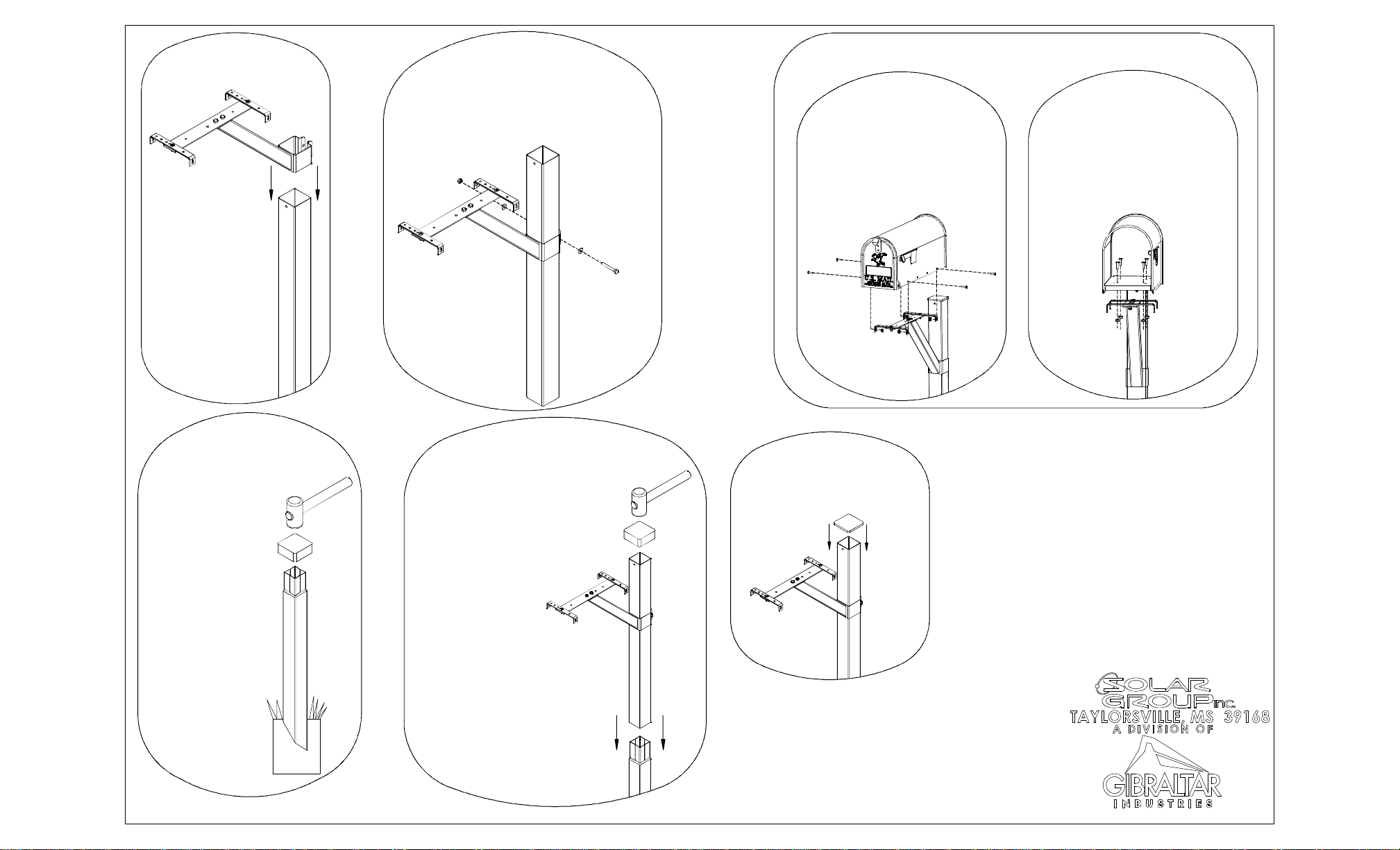
Step #3/ Paso #3
Slide the Cross-Arm Assembly onto
the Top Post. Position the
Cross-Arm Assembly so that the
bottom of the Cross-Arm Assembly
is 18 3/4'' from the bottom of the
Top Post.
Deslice el ensamlaje del travesaño
sobre el poste superior. Coloque el
ensamblaje del travesaño de
manera que la parte inferior del
mismo esté a 18 3/4 pulgadas de la
parte inferior del poste superior.
Fije el conjunto de travesaño al poste superior con perno hexagonal, la
arandela (2) y la tuerca hexagonal negro. Después de la instalación, el
conjunto de travesaño podrá que sea necesario ajustar. (No apriete
demasiado).
Attach the Cross-Arm Assembly to the Top Post using Hex Bolt A, (2)
Washer, and Black Hex Nut. After installation, the Cross-Arm Assembly
may need to be adjusted. (Do not over tighten.)
Step #4/ Paso #4
Step #5/ Paso #5
On the Bottom Post place a
mark 18'' away from the pointed
end. Use the Pounding Block
and a hammer to drive the
Bottom Post into the ground
stopping at the 18'' mark. While
driving the Bottom Post into the
ground, make sure it remains
level.
En el poste inferior, coloque
unamarca a 18 pulgadas del
extremo con punta. Utlice el
bloque para martillar y un martillo
para clavar el poste inferior en el
suelo y pare en la marca de 18
pulgadas. Mientras clava el
poste inferior en el suelo,
asegúrese de que permanezca
nivelado.
Slide the Top Post onto the
Bottom Post. Use the Pounding
Block and a hammer to secure
the Top Post to the Bottom
Post. While securing the Top
Post to the Bottom Post, make
sure the post assembly remains
level.
Step #6/ Paso #6
Deslice el poste superior sobre
el poste inferior. Utilice el
bloque para martillar y un
martillo para sequrar el poste
superior al poste inferior.
Mientras fija el poste superior al
poste inferior, asegúrese de
que el ensamblaje del poste
permanezca nivelado.
Step #7/ Paso #7
Insert the Cap into the Top Post.
Coloque la tapa en el poste superior.
Mailbox Installation/ Instalación del buzón
Attach mailbox to post assembly using (4) Screws
and (4) Hex Nuts.
Option #1: Side Mounting
Fije la buzón para el puesto Asembly usando (4)
Tornillos y (4) tuercas hexagonales.
Opción # 1: Montaje Lateral
Attach mailbox to post assembly using (4) Screws
and (4) Hex Nuts.
Option #2: Bottom Mounting
Fije la buzón para el puesto Asembly usando (4)
Tornillos y (4) tuercas hexagonales.
Opción # 2: Montaje Inferior

Popular Outdoor Furnishing manuals by other brands

West Elm 5866061 quick start guide

West Elm

West Elm 5866061 quick start guide

Polywood MNB484 Assembly instructions

Polywood

Polywood MNB484 Assembly instructions

Zest 4 Leisure Log Chest Assembly instructions

Zest 4 Leisure

Zest 4 Leisure Log Chest Assembly instructions

Homebase ANDORRA 2 SEATER SWING SET instruction manual

Homebase

Homebase ANDORRA 2 SEATER SWING SET instruction manual

Yard Craft Canterbury Assembly manual

Yard Craft

Yard Craft Canterbury Assembly manual

Dura Trel Elmwood Trellis 11190 Assembly instruction

Dura Trel

Dura Trel Elmwood Trellis 11190 Assembly instruction

HAMPTON BAY FTS61192 Use and care guide

HAMPTON BAY

HAMPTON BAY FTS61192 Use and care guide

TREX TXC23 Assembly instructions

TREX

TREX TXC23 Assembly instructions

HAMPTON BAY 176-411-5FP-V2 Use and care guide

HAMPTON BAY

HAMPTON BAY 176-411-5FP-V2 Use and care guide

HOMEDEPOT XWG-143 instruction manual

HOMEDEPOT

HOMEDEPOT XWG-143 instruction manual

HAMPTON BAY St. Lucia 4 Piece Deep Seating Set... Use and care guide

HAMPTON BAY

HAMPTON BAY St. Lucia 4 Piece Deep Seating Set... Use and care guide

Dura-Max Premier Gazebo installation instructions

Dura-Max

Dura-Max Premier Gazebo installation instructions

Members Mark Fremont BGV01523-4SC Assembly instructions & user manual

Members Mark

Members Mark Fremont BGV01523-4SC Assembly instructions & user manual

HAMPTON BAY Fernlake FBS60416B Use and care guide

HAMPTON BAY

HAMPTON BAY Fernlake FBS60416B Use and care guide

Members Mark Hastings AAX08800-9SC Assembly instructions & user manual

Members Mark

Members Mark Hastings AAX08800-9SC Assembly instructions & user manual

TREX Outdoor Furniture TXA15 Assembly instructions

TREX

TREX Outdoor Furniture TXA15 Assembly instructions

HAMPTON BAY A211030301 Use and care guide

HAMPTON BAY

HAMPTON BAY A211030301 Use and care guide

HAMPTON BAY GFS00679B Use and care guide

HAMPTON BAY

HAMPTON BAY GFS00679B Use and care guide

manuals.online logo
manuals.online logoBrands
  • About & Mission
  • Contact us
  • Privacy Policy
  • Terms and Conditions

Copyright 2025 Manuals.Online. All Rights Reserved.