SOLAREVER SE-BAT SYS-HV User manual
SE-BAT Lithium-ion Battery
User Manual
50Ah
Copyright Declaration
UL
The copyright of this manual belongs to Solarever Tecnologia de America S.A.de C.V. Any
corporation or individual should not plagiarize, partially or fully copy it (including software, etc.),
and reproduction or distribution in any form or by any means shall not be allowed. All rights
reserved. Solarever Tecnologia de America S.A.de C.V. reserves the right of nal interpretation. The
information contained herein is subject to change without notice.
www.solarever.com.mx
Solarever Tecnologia de America S.A.de C.V.
Autopista Mexico-Queretaro KM 71.9, S/N Noxtongo Tepeji del
Rio de Ocampo C.P. 42885, Hidalgo Mexico
Tel.: +55 4364 0437
E-mail: contacto@solarever.com.mx 614.00748.00

CONTENTS
1 NOTE ON THIS MANUAL..............................................................................................................................................1
1.1 SCOPE OF VALIDITY............................................................................................................................................1
1.2 TARGET GROUP......................................................................................................................................................1
1.3 SYMBOLS USED.....................................................................................................................................................1
2 SAFETY.......................................................................................................................................................................................2
2.1 SAFETY INSTRUCTIONS..................................................................................................................................2
2.1.1 GENERAL SAFETY PRECAUTIONS..................................................................................................2
2.1.2 EXPLANATION OF SYMBOLS.............................................................................................................3
2.2 RESPONSE TO EMERGENCY SITUATIONS..........................................................................................5
2.2.1 LEAKING BATTERIES..................................................................................................................................5
2.2.2 FIRE........................................................................................................................................................................5
2.2.3 WET BATTERIES AND DAMAGED BATTERIES........................................................................5
2.3 QUALIFIED INSTALLER.....................................................................................................................................6
3 PRODUCT INTRODUCTION......................................................................................................................................7
3.1 PRODUCT OVERVIEW.......................................................................................................................................7
3.1.1 DIMENSION AND WEIGHT..................................................................................................................7
3.1.2 APPEARANCE................................................................................................................................................8
3.2 BASIC FEATURES................................................................................................................................................10
3.2.1 FEATURES......................................................................................................................................................10
3.2.2 CERTIFICATIONS......................................................................................................................................10
3.3 SPECIFICATIONS.................................................................................................................................................11
3.3.1 SE-BAT SYS-HV CONFIGURATION LIST.....................................................................................11
3.3.2 PERFORMANCE.........................................................................................................................................11
4 INSTALLATION..................................................................................................................................................................12
4.1 INSTALLATION PREREQUISITES..............................................................................................................12
4.2 SAFETY GEAR.......................................................................................................................................................12
4.3 TOOLS.......................................................................................................................................................................13
4.4 INSTALLATION.....................................................................................................................................................13
4.4.1 CHECK FOR TRANSPORT DAMAGE..........................................................................................13
4.4.2 UNPACKING.................................................................................................................................................13
4.4.3 ACCESSORIES.............................................................................................................................................14
4.4.4 BATTERY INSTALLATION STEPS....................................................................................................16
1 Note on this Manual
1.1 Scope of Validity
This manual is an integral part of SE-BAT Series. It describes the assembly,
installation, commissioning, maintenance and failure of the product. Please read
it carefully before operating.
SE-BAT SYS-HV
1.2 Target Group
This manual is for qualied ele tricians. The tasks described in this manual may
only be performed by qualied ele tricians.
1.3 Symbols Used
The following types of safety instructions and general information appear in this
document described as below:
DANGER!
“DANGER” indicates a hazardous situation which, if not avoided,
will result in death or serious injury.
WARNING!
“WARNING” indicates a hazardous situation which, if not avoided,
could result in death or serious injury.
CAUTIOIN!
“CAUTION” indicates a hazardous situation which, if not avoided,
could result in minor or moderate injury.
NOTE!
“NOTE” provides tips that are valuable for the optimal operation of
your product.
4.5 OVERALL INSTALLATION.....................................................................................................................................18
4.5.1 CABLE CONNECTION...................................................................................................................................20
4.5.2 CONNECTING POWER CABLES............................................................................................................22
4.5.3 CONNECTING POWER LINES.................................................................................................................26
4.5.4 CONNECTING CAN COMMUNICATION CABLE.......................................................................27
4.5.5 CONNECTING RS485 COMMUNICATION CABLE...................................................................28
4.5.6 CONNECTING GROUND WIRE..............................................................................................................29
4.6 OVERVIEW OF INSTALLATION..........................................................................................................................31
5 COMMISSIONING...................................................................................................................................................................32
5.1 CONFIGURING BATTERY SYSTEM....................................................................................................................32
5.2 COMMISSIONING.........................................................................................................................................................33
5.3 STATUS INDICATORS...............................................................................................................................................35
5.3.1 BMS ............................................................................................................................................................................35
5.3.2 BATTERY PACK....................................................................................................................................................36
5.4 SHUTTING DOWN SE-BAT SYSTEM.............................................................................................................36
6 TROUBLESHOOTING............................................................................................................................................................37
6.1 TROUBLE SHOOTING.............................................................................................................................................37
7 DECOMMISSIONING............................................................................................................................................................40
7.1 DISMANTLING THE BATTERY............................................................................................................................40
7.2 PACKAGING....................................................................................................................................................................40
SE-BAT-MA H 5.8
NOTE: There are 4 models for SE-BAT system, which includes BMS and battery
pack(s). Please refer to section 3.3.1 SE-BAT SYS-HV Conguration List on page 11
for detailed models.
SE-BAT PACK-HV
SE-BAT-SL H 5.8
8 MAINTENANCE AND WARRANTY.............................................................................................................................41
23
2 Safety
2.1 Safety Instructions
For safety reasons, installers are responsible for familiarizing themselves with the
contents of this manual and all warnings before performing installation.
2.1.1 General Safety Precautions
Observe the following precautions:
ŸRisks of explosion
–Do not subject the battery pack to strong impacts.
–Do not crush or puncture the battery pack.
–Do not dispose of the battery pack in a re.
ŸRisks of re
–Do not expose the battery pack to temperatures in excess of 13 .1℉/55°C.
–Do not place the battery pack near a heat source, such as a replace.
–Do not expose the battery pack to direct sunlight.
–Do not allow the battery connectors to touch conductive objects such as
wires.
ŸRisks of electric shock
–Do not disassemble the battery pack.
–Do not touch the battery pack with wet hands.
–Do not expose the battery pack to moisture or liquids.
–Keep the battery pack away from children and animals.
ŸRisks of damage to the battery pack
–Do not allow the battery pack to get in contact with liquids.
–Do not subject the battery pack to high pressures.
–Do not place any objects on top of the battery pack.
SE-BAT SYS-HV can be used only in the household energy eld. It is not allowed to
be used in other industries, such as the medical equipment and automotive
application.
WARNING!
Please don't crush or impact the battery, and always dispose it
according to the safety regulation.
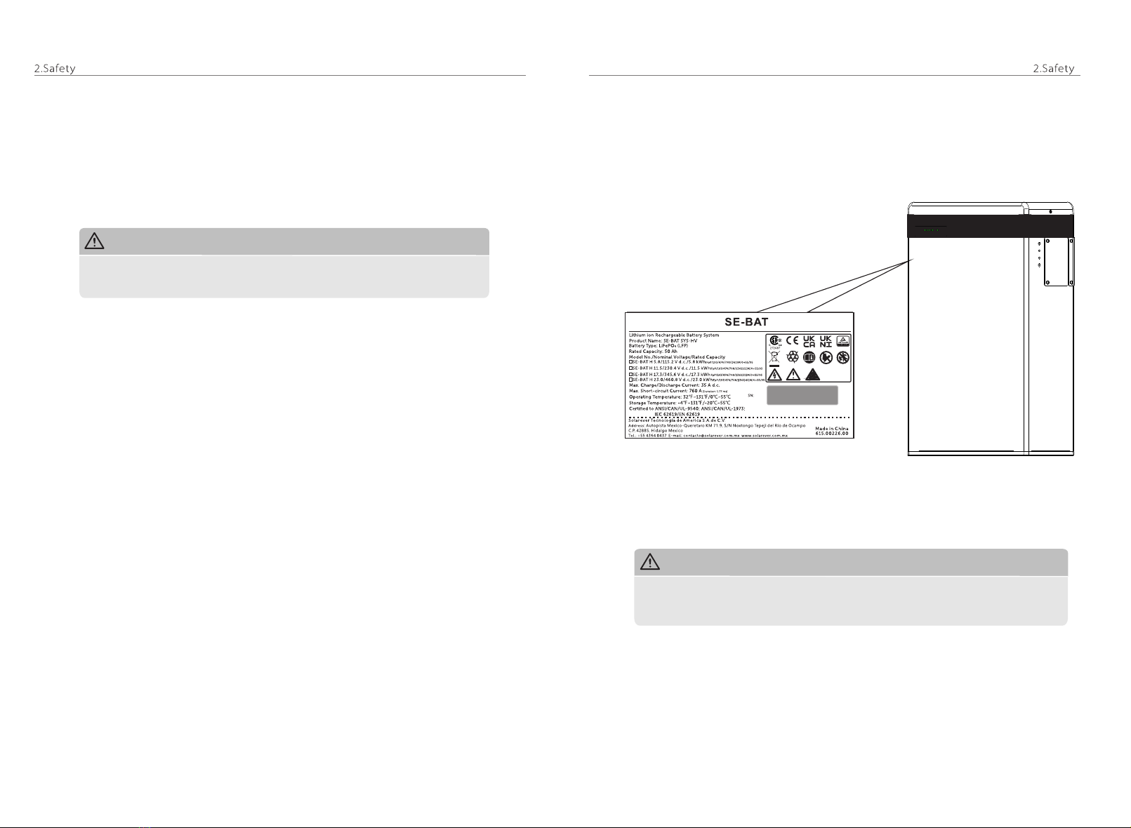
2.1.2 Explanation of Symbols
This section gives an explanation of all the symbols shown on the SE-BAT system
and on the warning label.
CAUTION!
If the battery is not installed within one month after receiving the battery, the
battery must be charged till the SOC is more than 50% for maintenance.

45
Wear protecitve glasses
Observe enclosed documentation.
Keep the battery system away from open ames or i nition
sources.
Keep the battery system away from children.
Danger of high voltages.
Danger to life due to high voltages in the battery system!
Danger.
Risk of electric shock!
The battery pack may explode.
Symbol Explanation
The PV inverter is compliant with TUV
The battery system should be disposed of at a proper facility
for environmentally safe recycling.
The battery system should not be disposed together with the
household waste.
Disposal information can be found in the enclosed documentation.
2.2 Response to Emergency Situations
2.2.1 Leaking Batteries
If the battery leaks electrolyte which is corrosive, avoid contact with the leaking
liquid or gas. Direct contact may lead to skin irritation or chemical burns. If one is
exposed to the leaked substance, do these actions:
Accidental inhalation of harmful substances:Evacuate people from the
contaminated area , and seek medical attention immediately.
Eye contact: Rinse eyes with owing water or 15 minutes, and seek medical
attention immediately.
Dermal contact: Wash the affected area thoroughly with soap and water, and
seek medical attention immediately.
Ingestion: Induce vomiting, and seek medical attention immediately.
2.2.2 Fire
In case of a re, make sure an ABC or carbon dioxide extinguisher is nearby.
WARNING!
The battery pack may catch re when heated above 150°C.302℉/
If a re breaks out where the battery pack is installed, do
these actions:
1. Extinguish the re before the batterry pack catches re;
2. If the battery pack has caught re, do not try to
extinguish the re. Evacuate people immediately.
WARNING!
If the battery pack catches re, it will produce noxious and poisonous gases.
Do not approach.
2.2.3 Wet Batteries and Damaged Batteries
If the battery pack is wet or submerged in water, do not try to access it.
If the battery pack seems to be damaged, they are not t or use and may pose a
danger to people or property.
Please pack the battery in its original container, and then return it to Solarever or
your distributor.
CAUTION!
CSA certied
CE mark.
The inverter complies with the requirements of the applicable
CE guildlines.
272687
Damaged batteries may leak electrolyte or produce ammable gas. If
you suspect such damage, immediately contact Solarever for advice
and information.

2.3 Qualied nstaller
WARNING!
All operations of SE-BAT SYS-HV relating to electrical connection and
installation must be carried out by qualied personne.
A skilled worker is dened as a trained and qualied electrician or installer who
has all of the following skills and experience:
ŸKnowledge of the functional principles and operation of on-grid systems
ŸKnowledge of the dangers and risks associated with installing and using
electrical devices and acceptable mitigation methods
ŸKnowledge of the installation of electrical devices
ŸKnowledge of and adherence to this manual and all safety precautions and
best practices
67
3 Product Introduction
3.1 Product Overview
For safety reasons, installers are responsible for familiarizing themselves with the
contents of this manual and all warnings before performing installation.
3.1.1 Demension and Weight
A battery management system (BMS) is any electronic system that manages a
rechargeable battery.
Battery pack is a type of electrical battery which can be charged, discharged into
a load.
A battery system includes BMS and battery pack(s).
SE-BAT-SL H 5.8
(Battery Pack)
SE-BAT-MA H 5.8
Length
Width
Height
Weight
SE-BAT-MA H 5.8 SE-BAT-SL H 5.8
3. Product Introduction
18.66 in/474.00 mm
7.60 in/193.00 mm
27.87 in/708.00 mm
159.2 lbs/72.2 kg
25.47 in/647.00 mm
151.0 lbs/68.5 kg
18.66 in/474.00 mm
7.60 in/193.00 mm
27.87 in/708.00 mm
25.47 in/647.00 mm
18.66 in/474.00 mm
7.60 in
193.00 mm
18.66 in/474.00 mm
7.60 in
193.00 mm

ŸSection view of SE-BAT-SL H 5.8
3. Product Introduction 3. Product Introduction
89
3.1.2 Appearance
ŸSection view of SE-BAT-MA H 5.8
Object Mark Description
Ⅰ
Ⅱ
Ⅲ
Ⅳ
BAT+/BAT-
CAN
GND
/
Charge/Discharge Connectors
CAN Connector
GND
Air Valve
Object Mark Description
Ⅰ'
Ⅱ'
Ⅲ'
Ⅳ'
Ⅴ'
XPLUG
+
RS485 I
GND
/
Ⅰ
Ⅱ Ⅲ
Ⅳ
Ⅴ Ⅵ
Ⅶ
ⅧPower Connector’ to YPLUG of upper battery pack
RS485 Connector to RS485 II of upper battery pack
GND
RS485 Connector to RS485 I of next battery pack
Power Connector’ to XPLUG of next battery pack, or
to “-” of the same pack
Air valve
BAT+BAT-
CAN
-YPLUG
RS485 II
Ⅲ
+
XPLUG
RS485 I
-YPLUG
RS485 II
Ⅰ'Ⅱ’'
Ⅲ’'Ⅳ’'
Ⅴ’'
Ⅵ’'Ⅶ'
Ⅷ’'Ⅳ'
Power Connector to “-” of upper battery pack
Power Connector to + of next battery pack, or to YPLUG
of the same pack
RS485 Connector to RS485 I of next battery pack
Power Button
DIP Switch
Circuit Breaker
Ⅴ
Ⅵ
Ⅶ
Ⅷ
Ⅸ
Ⅹ
-
YPLUG
RS485 II
POWER
DIP
ON/OFF
Power Connector’ to XPLUG of next battery pack,
or to “-” of the same pack
Power Connector to + of next battery pack, or to
YPLUG of the same pack
Ⅵ'
Ⅶ'
Ⅷ'
-
YPLUG
RS485 II
X
IX

3.2 Basic Features
3.2.1 Features
The SE-BAT SYS-HV is one of the advanced energy storage systems on the market
today, incorporating state-of-the-art technology, high reliability, and convenient
control features shown as below:
Ÿ90% DOD
Ÿ99% Faradic charge efficiency
Ÿ95% Battery roundtrip efficiency
ŸCycle life > 6000 times
ŸSecondary Protection by hardware
ŸIP55 protection level
ŸSafety & Reliability
ŸSmall footprint
ŸFloor or wall mounting
3.2.2 Certications
3. Product Introduction 3. Product Introduction
10 11
SE-BAT system safety
Battery cell safety
UN number
Hazardous materials classication
UN transportation testing requirements
International protection marking
CE, FCC, RCM, TUV (IEC 62619), UL 1973
UL 1642
UN 3480
Class 9
UN 38.3
IP 55
3.3 Specications
3.3.1 SE-BAT SYS-HV Conguration List
3.3.2 Performance
Model Battery Pack Energy(kWh) Voltage (V)
No.
1
2
3
SE-BAT H 5.8
SE-BAT H 11.5
SE-BAT H 17.3
SE-BAT-MA H 5.8*1
SE-BAT-MA H 5.8*1+SE-BAT-SL H 5.8*1
SE-BAT-MA H 5.8*1+SE-BAT-SL H 5.8*2
5.8
11.5
17.3
100-131
200-262
300-393
SE-BAT-MA H 5.8 SE-BAT-SL H 5.8
Dimension (in/mm)
Weight (kg)
Nominal Voltage (V d.c.)
Operating Voltage (V d.c.):
Nominal Capacity (Ah)
Nominal Energy (kWh) :
Recommend Charge/Discharge Current (A d.c.):
Standard Power (kW)
Maximum Power (kW)
72.2
115.2
100-131
50
5.8
25
2.9
4.0
68.5
115.2
100-131
50
5.8
25
2.9
4.0
Altitude (m)
Faradic Charge Efficiency (25°C/77°F)
Battery Roundtrip Efficiency (C/3,25°C/77°F)
Expected Lifetime (25°C/77°F)
Cycle Life (90% DOD, 25°C/77°F)
Available Operating Temperature
Optimal Operating Temperature
Storage Temperature
Ingress Protection
≤2000
99%
95%
10 years
6000 cycles
IP55
Test conditions: 100% DOD, 0.5C charge & discharge @+25°C
Discharging: 41 /0 ~5 and /45-55 will be rating 32℉~℉°C °C 113℉~131℉°C
90% DOD; System usable energy may vary with inverter different setting
Charging: 32℉~41℉/0°C~5°C and 104℉~122℉/40°C~50°C will be rating
1
2
1
Usable Energy (kWh) :
Max. Сharge/Discharge Current (A d.c.) :
5.2
35
5.2
35
2
3
3
32℉~131℉/0°C~55°C
59 ~95 15 ~35℉ ℉/ °C °C
-4℉~131℉/-20°C~55°C (3 months)
32℉~104℉/0°C~40°C (1 year)
18.66*7.60*27.87
474.00*193.00*708.00
18.66*7.60*25.47
474.00*193.00*647.00

4 Installation
4.1 Installation Prerequisites
Make sure that the installation location meets the following conditions:
ŸThe building is designed to withstand earthquakes
ŸThe location is far away from the sea, to avoid salt water and humidity
ŸThe oor is at and level
ŸThere are no ammable or explosive mateials nearby
ŸThe ambience is shady and cool, keep away from heat and avoid direct
sunlight.
ŸThe temperature and humidity stays at a constant level.
ŸThere is minimal dust and dirt in the area.
ŸThere is no corrosive gases present, including ammonia and acid vapor.
ŸThe ambient temperature is within the range from 32℉113℉45°C, and the /0°C to /
optimal ambient temperature is between ℉ ℉ .9/15°C and 95 /35°C
NOTE!
If the ambient temperature is outside the operating range, the battery pack
stops operating to protect itself. The optimal temperature range for the battery
pack to operate is 15°C to 35°C. Frequent exposure to harsh temperatures may
deteriorate the performance and lifetime of the battery pack.
4.2 Safety Gear
Installation and maintenance personnel must operate according to applicable
federal, state and local regulations as well as the industry standards regarding the
product installation personnel shall wear safety gears, etc. in order to avoid short
circuit and personal injury.
Insulated gloves Safety goggles Safety shoes
4. Installation
12 13
4. Installation
4.3 Tools
These tools are required to install the SE-BAT system.
Torque screw driver Phillips-screw driver Socket nut wrench
Phillips-head screw driver Flat-head screw driver Torque wrench
Tape measure Drill Pencil or Marker
4.4 Installation
4.4.1 Check for Transport Damage
Make sure the battery is intact during transportation. If there are some visible
damages, such as cracks, please contact your dealer immediately.
4.4.2 Unpacking
Unpacking the battery package by cutting the packing tape and make sure the
battery packs and the relevant items are complete. See package items on section
4.4.3, please check the packing list carefully, if there's any item missing, please
contact Solarever or your distributer directly.
CAUTION!
According to regional regulations, several people may be required for
moving equipment.
WARNING!
Please strictly follow the installation steps. Solarever will not answer for
any hurting or loss arising by incorrectly assembling and operation.
NOTE!
The SE-BAT battery pack is rated at IP55 and thus can be installed
outdoors as well as indoors. However, if installed outdoors, do not allow the
battery pack to be exposed to direct sunlight and moisture.
4. Installation 4. Installation
15
14
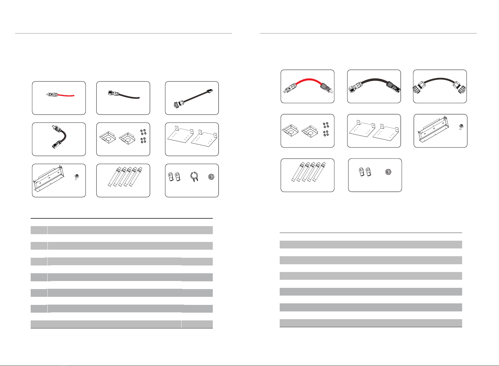
4.4.3 Accessories
E
HJ
The table below lists the number of each component.
SE-BAT-MA H 5.8:
K
Object
A
B
C
D
E
F
G
H
I
J
K
L
M
Description
Power line between Inverter and SE-BAT-MA H 5.8 (+) ( )6.56 ft/2.00 m)
Power line between Inverter and SE-BAT-MA H 5.8 (-) ( )6.56 ft/2.00 m
CAN communication cable ( )6.56 ft/2.00 m
Series-connected plug
Cover plate2
M4 screw
Cover plate2
Wall bracket
M5 screw
Expansion bolt
Ring terminal (for grounding)
Power cable disassembling tool
Grounding nut
Quantity
1
1
1
1
2
8
2
1
1
5
2
1
2
L
SE-BAT-SL H 5.8:
Quantity Object
A1
B1
C1
D1
E1
F1
G1
H1
I1
J1
K1
Description
Power cable between battery packs ( )259.59 in/650.00 mm
Power cable’ between battery packs ( )259.59 in/650.00 mm
Rs485 communication cable ( )259.59 in/650.00 mm
Cover plate2
M4 screw
Cover plate2
Wall bracket
M5 screw
Expansion bolt
Ring terminal (for grounding)
Grounding nut
A(Red cable)B(Black cable) C
D(Black cable)
A1
F
I
B1 C1
G1 H1F1
I1
D1 E1
1
1
1
2
8
2
1
1
5
2
2
The table below lists the number of each component.
G
M
J1 K1
RS485cable*1
4. Installation 4. Installation
16 17
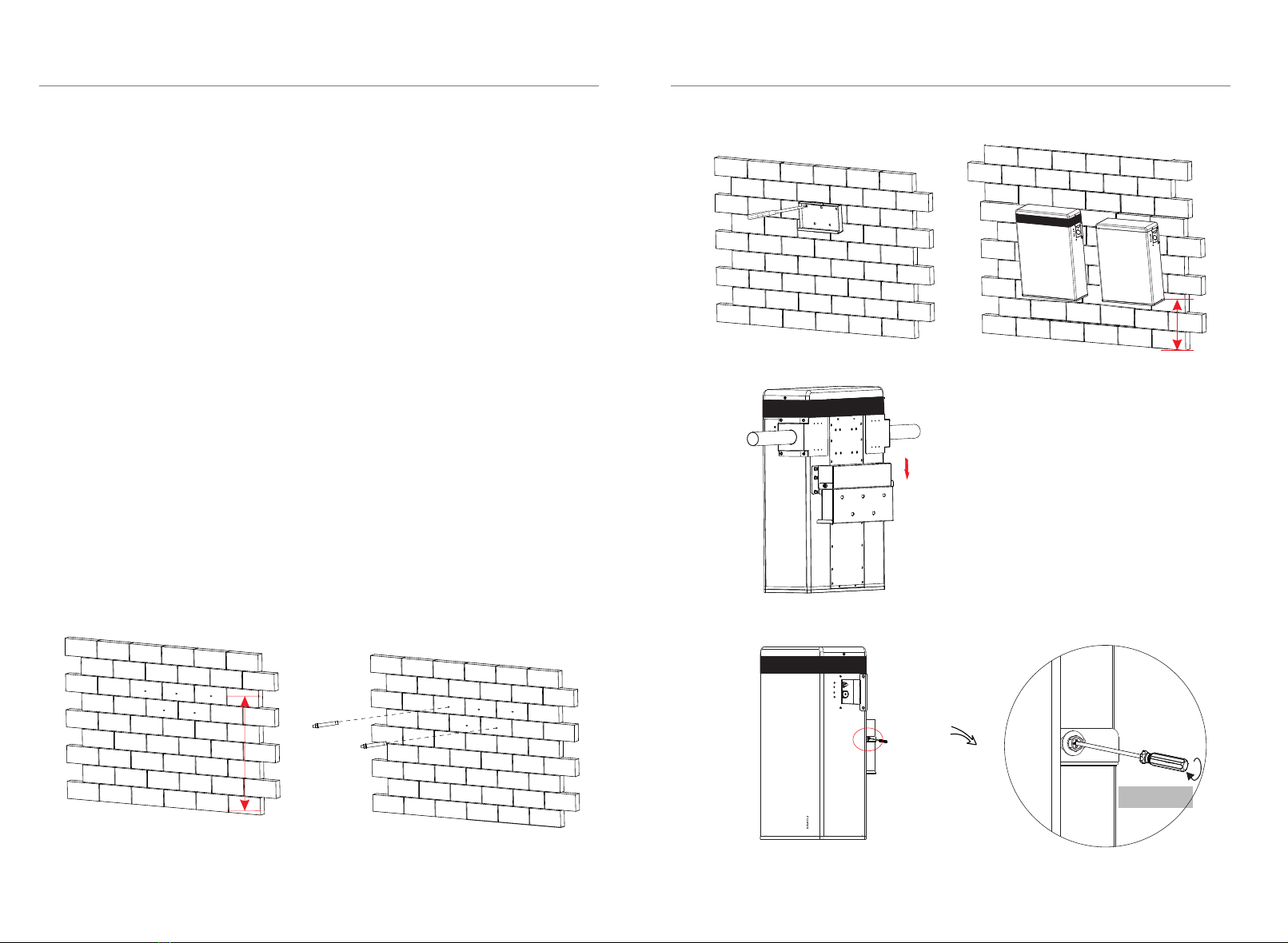
4.4.4 Battery Installation Steps
It is recommended that the space between battery packs is more than
300mm.
Steps (for SE-BAT-MA H 5.8 or SE-BAT-SL H 5.8):
Make sure the wall is strong enough to withstand the weight of battery packs.
Step 1: x the wall brac et (H or G1) on the wall
ŸUse the wall bracket as a template to mark the position of the 5 holes
ŸDrill holes with φ 0.39 in/10 mm drill, make sure the holes are deep enough (at least
80mm) for installing and tightening the expansion bolts (J or I1)
ŸInstall the expansion bolts in the wall, and screw the bracket by using the
wrench.
Step 2: Match the battery with the wall bracket
ŸTransport the battery to the wall bracket
ŸHang the battery over the wall bracket, move the battery close to it, and
match it on the wall bracket
Step3: Lock the joint between hanging board and wall bracket with M5
combinationscrew (I or H1).
Note: 1 Keep the distance from installation point to the oor less than 259.59 in/650.00 mm..
Side view of hanging the battery to
the wall bracket.
Torque: 2 N·m
2. It is recommended to keep a distance of 32.44 in/824.00 mm between the center of
wall bracket and the wall bracket.
3. It is recommended to keep a distance of 13.78 in/350.00 mm between battery packs,
Must be between 12.60~14.96 in/320.00 ~380.00 mm.
1.18 in/30 mm<height<11.81 in/300 mm
14.96 in/380 mm<height<25.59 in/650 mm
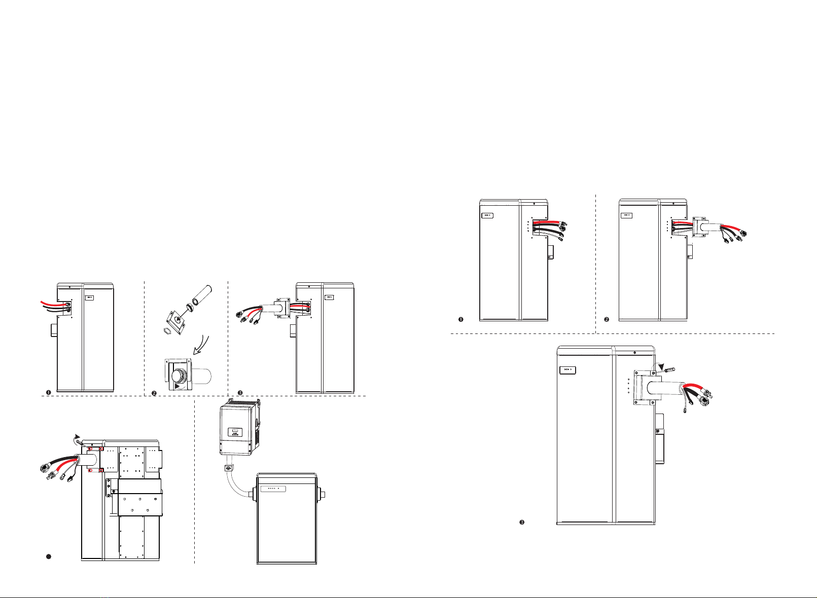
Overall Installation
It is recommended to protect the cables by using corrugated pipe.
1. Connect all the cables on the left side of SE-BAT-MA H 5.8.
2. Install cover plates and conduits.Install cover plate and conduit. Pass the
3. Get the cables through theconduit .
right side of SE-BAT-MA H 5.8 to make a complete circuit.
6. Set the cables into the groove of metal plates and screw them back to the
battery pack on both sides.
A1
A2
A3
A4
conduits(A1) and joint(A2) through the round hole of the cover plate(A3) and
tighten it with the Hexagon flange head screw(A4). These conduits must be
standard size and match the holes in the battery cover plate. The catheter fittings
must be waterproof and preferably insulated. (conduit size: 1-1/1 in/12.7-12.7 mm)
4. Finally, screw the front and side cover plates onto the battery.(torque:2N.M)
5 . DO remember to insert the series-connected plug at “-” and “YPLUG” on the
4.5
For SE-BAT-MA H 5.8:
4
For SE-BAT-MA H 5.8 + 1~3 battery packs:
1. Connect the cables at one end of the SE-BAT-MA H 5.8/SE-BAT-SL H 5.8.
2. Get the cables through theconduit. (conduit size: 1-1/2 in/12.7~25.4 mm)
3. Finally, screw the front and side cover plates onto the battery.(torque:2N.M)
4. DO remember to insert the series-connected plug at “-” and “YPLUG” on the
right side of last battery pack to make a complete circuit.
(please refer to section 4.5 For SE-BAT-MA H 5.8 step 2)
18 19
+
-
+
-
+
-
+
-
+
-

Please refer to section 4.5 for the installation of conduit and cover plate, and
then make connection.
On the left side of SE-BAT-MA H 5.8 , after the charging cables (please refer to
section 4.5.2) and CAN communication cable (please refer to section 4.5.4) are
correctly connected, screw the terminal box_small (J) with M4 srews and lock
the terminal box cover (K) also with M4 screws.
On the right side of SE-BAT-MA H 5.8 , after the battery modules (please refer to
section 4.5.1 For 2~3 battery modules) are correctly ,screw the terminal
box_medium_right (I1) with M4 screws and lock the terminal box cover (K1) in
the same way as BMS.
Please see the installation diagram on the right. (screw torque: 2 N·m)
4. Installation 4. Installation
For 2~3 battery modules:
The power cable between battery modules (A1) is different from the one that
between BMS and battery module (C). The other end of the power cable is black,
and this color is connected to YPLG (Ⅴ’), which is on the right side of the battery
module.
1. Connect YPLUG (Ⅴ’)on the right side of battery module to XPLUG (Ⅰ’) on the
left side of the second battery module. The rest battery modules are connected
in the same way. The following gue shows that four battery modules are
connected.
2. Before connecting the cables to XPLUG (Ⅰ’) on the left side of follow-up
battery module, lock the terminal box_medium_right(I1) on the right side of
previous battery module with M4 screws(H1), and get the cables through the
conduits which length is 7.87~9.45 in/200.00~240.00 mm, then lock the terminal
box cover (K1) with M4 screws.
3. Lock the terminal box_medium_left(J1) on the left side of follow-up battery
module, and keep the terminal box cover (K1) unlocked until the cables are
correctly connected to the YPLUG.
GND RS485
Power Cable
GND
RS485
Power Cable
4.5.1 Cable Connection
20 21
+
-
+
-

4. Installation 4. Installation
1. The only step of connecting power cable for SE-BAT-MA H 5.8 is connecting the
series-connected plug to “-” and “YPLUG” on the right side. The series-connected
plug is used to make a complete circuit.
-YPLUG
RS485 II
For SE-BAT-MA H 5.8 + 1~3 battery packs:
1. Connect “-” (Ⅴfor SE-BAT-MA H 5.8 or ’ for SE-BAT-SL H 5.8) on the right side Ⅵ
to “+” ’) on the left side of the next battery pack. (Ⅱ
2. Connect “YPLUG” ( for SE-BAT-MA H 5.8 or ’ for SE-BAT-SL H 5.8) on the right Ⅵ Ⅶ
side to “XPLUG” (Ⅰ’) on the left side of the next battery pack.
3. The rest battery packs are connected in the same way.
4. Insert the series-connected plug at “-” and “YPLUG” on the right side of last
battery pack to make a complete circuit.
-YPLUG
RS485 II
-YPLUG
RS485 II
4.5.2 Connecting Power Cables
For SE-BAT-MA H 5.8:
XPLUG +
RS485
-YPLUG
RS485 II
-YPLUG
RS485 II
-YPLUG
RS485 II
22 23

3. Pass the other end of the charging cable through the inverter's pipe.Insert the
trip head of each wire into the hole.
NOTE!
1. When connecting the cable to SE-BAT-MA H 5.8, t the wo connectors together
until the connection audibly locks into place.
2. Check to make sure the connection is securely locked.
3. Don't shake both ends of the cable at the joint once the connection is locked.
4.5.3 Connecting Power Lines
4. Installation 4. Installation
Connecting Charging Cables between Inverter and SE-BATsystem:
Ø
This step is going to connect power lines between Inverter and SE-BAT system.
The default length of power lines are 2 meters, so customers can6.56 feet/
propriately cut the cable accroding to the actual installation environment. As a
result, eachpower line has one terminal block when leaving the factory, and
customers need to connect the other end of terminal block by themselves.
1. Connect the positive cable (+)(A) and negative cable (-)(B) through the accessory
Cover plate1 to the corresponding port as shown in the following gue.
BAT- BAT+
CAN
-
+
BAT- BAT+
CAN
24 25

-
+
BAT- BAT+
CAN
Disassemble the power line by plugging the slot type screwdriver to the terminal
groove of charging cable. Please see the illustration as shown below:
BAT- BAT+
CAN
BAT- BAT+
CAN
DO NOT disassemble power cables when the SE-BAT system is not
turned off, otherwise there will be an arc discharge that could cause
serious injury!
CAUTION!
Disassembling Power Line (on BAT+, BAT-, “+”, XPLUG port)
Ø
4. Installation 4. Installation
-YPLUG
RS485 II
Disassemble the power line by plugging the Power cable disassembling tool(L)
to the terminal groove of charging cable. Please see the illustration as shown
below:
-YPLUG
RS485 II
-YPLUG
RS485 II
Disassembling Power Cable (on ”-”, YPLUG port)
Ø
26 27
+
-
+
-

4. Installation 4. Installation
4.5.4 Connecting CAN Communication Cable
It is required for the BMS to communicate with the inverter for proper operation.
2. Connect the CAN communication cable to
the CAN connector (II) which is marked in red.
Insert the other end of the CAN communication
cable to the CAN connector. Assemble the cable
gland and screw the cable nut.
1. Insert one end of the CAN communication
cable (C) which has no cable nut directly to the
BMS port of the Inverter.
BAT- BAT+
CAN
The wire order of the communication cable is as follows:
1 2 3456 7 8
1) White with an orange stripe
2) Orange
3) White with a green stripe
4) Blue
5) White with a blue stripe
6) Green
7) White with a brown stripe
8) Brown
Sequence 1 2 3 4 5 6 7 8
CAN /GND /CAN_H CAN_L /A1 B1
4.5.5 Connecting RS485 Communication Cable
For SE-BAT-MA H 5.8:
There's no need to use RS485 communicaton cable.
For SE-BAT-MA H 5.8 + 1~3 battery packs:
Connect RS485 II ( for SE-BAT-MA H 5.8 orⅧ’ for SE-BAT-SL H 5.8) of upper Ⅶ
battery on the right side to RS485 I ( ’) of the follow-up battery pack which is on Ⅲ
the left. Assemble the cable gland and screw the cable nut.
Sequence 1 2 3 4 5 67 8
RS485I
RS485II
VCC_485
VCC_485
GND_485
GND_485
B2
B2
N-
N-
P+
P+
A2
A2
VCC_485_2
VCC_485_2
GND_485
GND_485
The wire order of the communication cable is as follows:
-YPLUG
RS485 II
-YPLUG
RS485 II
-YPLUG
RS485 II
+XPLUG
RS485 I
28 29
4. Installation 4. Installation
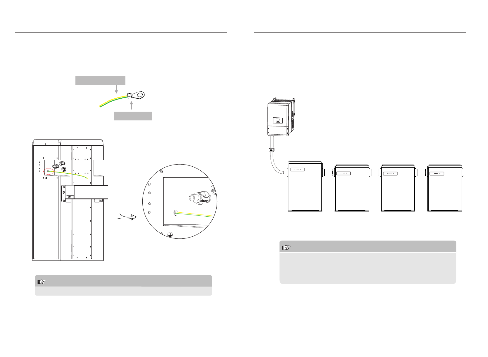
4.5.6 Connecting Ground Wire
CAUTION!
GND is mandatory!
The terminal point for GND connection is on the side of grooves as shown
below (torque: 1.5 N·m):
-YPLUG
RS485 II
Cable size: 10AWG.
ring terminal
-YPLUG
RS485 II
CAUTION!
One SE-BAT system is allowed to install one SE-BAT-MA H 5.8 plus at most
three battery packs. Connecting more than three battery packs will blow
the fuse, and the battery pack will be damaged. Please make sure the
number of battery packs meets the requirement.
4.6 Overview of Installation
The following diagram is a complete SE-BAT system installation with
SE-BAT-MA H 5.8 + three battery packs.
30 31
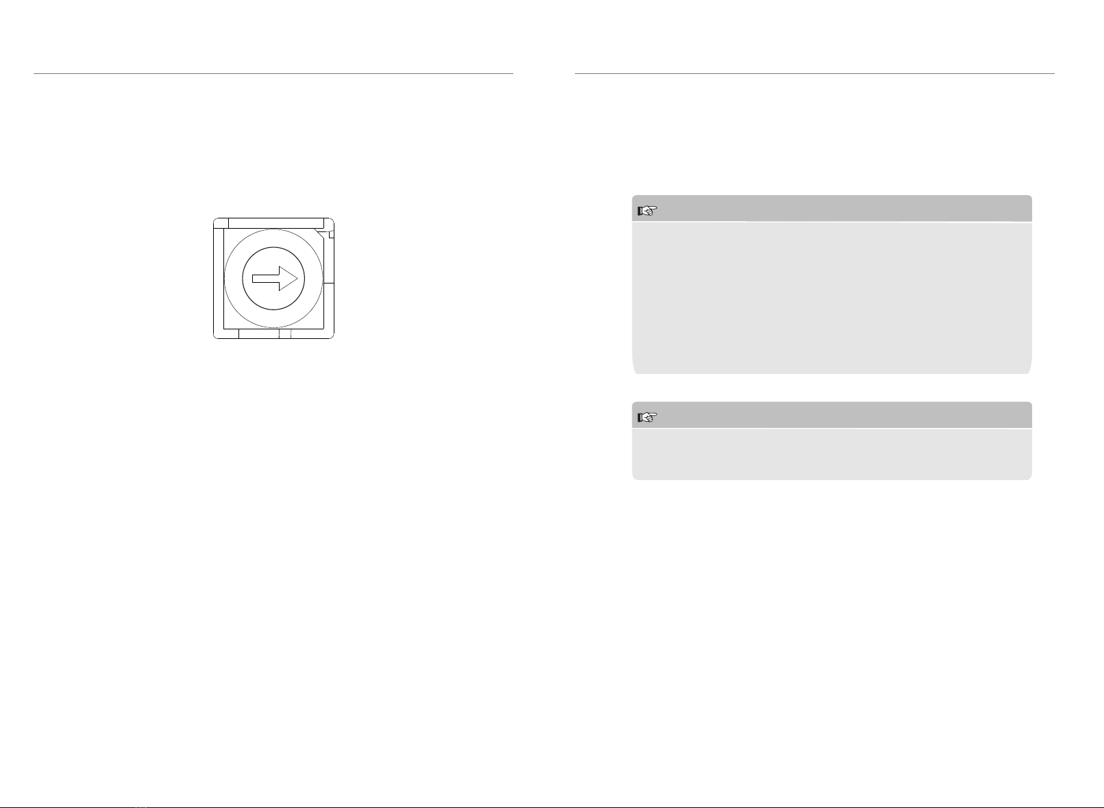
5 Commissioning
5.1 Conguing Battery System
The DIP switch is used to congue the number of battery packs which are
communicating to Inverter. The detailed conguration inormation is shown as
follows:
0
1
2
3
4
5
6
7
Conguration a tivated by inverters
0-
1-
2-
Matching SE-BAT-MA H 5.8 (default)
Matching SE-BAT-MA H 5.8 + 1*SE-BAT-SL H 5.8
Matching SE-BAT-MA H 5.8 + 2*SE-BAT-SL H 5.8
The black-start function is only used in the off-grid environment and there is no
other power supply.
Note: if the battery is started in black-start mode, although there is no BMS
communication, the port still has high voltage and there is a risk of electric
shock!
After the black-start mode is started, if the BMS communication has still not been
built within 3 minutes , the black start fails.
4-
5-
6-
Matching SE-BAT-MA H 5.8
Matching SE-BAT-MA H 5.8 + 1*SE-BAT-SL H 5.8
Matching SE-BAT-MA H 5.8 + 2*SE-BAT-SL H 5.8
Black-start conguration
Ø
5. Commissioning
5. Commissioning
NOTE!
When powering on the BMS, the system will start self-testing. If the
buzzer bips, it means DIP conguration fault or communication failue
occurs. If the buzzer bips, please check if the number of battery packs is
corresponding to the DIP conguration, and also check if the RS485
communication calbes are correctly connected. After these two
situation checked OK, press the POWER button to power on, and press
the POWER button again 10s later. In addition: The buzzer will only
alarm on the corresponding fault during the power-on self-test. After
the self-test is completed, it won't bip again even if the same fault
occurs.
NOTE!
Frequently pressing the POWER button may cause the system error.
Please make sure at least 10 seconds is needed when you are going to
press the POWER button from the last pressing operation.
5.2 Commissioning
32 33

Commissioning Steps
If all the battery packs are installed, follow these steps to put it in operation.
1. Remove the upper cover board of SE-BAT-MA H 5.8;
2. Remove the small cover plate;
3. Rotate the DIP to corresponding number with small tool accroding to the
number of battery pack(s) that has(have) been installed;
4. Move the circuit breaker to the ON position;
5. Press the POWER button to turn on the SE-BAT system;
6. Put the small cover plate back;
7. Reinstall the upper cover board to SE-BAT-MA H 5.8;
8. Power on the Inverter.
1
small cover plate
2
3
4
5
5. Commissioning
5. Commissioning
34 35
No.
1
2
3
Mode
Power off
Inverter sends Idle command
BMS Protection
Status of BMS
5.3 Status Indicators
The LED indicators on the front panel of the battery pack are showing the
operating status.
5.3.1 BMS
The capacity indicators show the SOC:
ŸWhen the battery pack is neither charging nor discharging, the indicator
lights off.
ŸWhen the battery pack is charging, part of the Blue LED is ashing with the
frequency of light on for 0.5s, light off for 0.5s, and part of the Blue LED keeps
light on. Take SOC 60% for instance, in charging state:
1. The rst wo Blue LED indicators keeps on
2. The third Blue LED indicator ashes once evey 1s
ŸWhen the battery pack is discharging, the Blue LED is ashing with the
frequency of light on for 1s, and light off for 4s. Take SOC 60% for instance, in
discharging state:
1. The rst three blue LED indicators ash once every 5s
The following table shows the status of BMS.
Charging Discharging
25% 50% 75% 100%
SOC Status
The Green LED is light on for 0.3s, and light o fffor 0.3s
The Green LED keeps light on
25% 50% 75% 100%
SOC Status 25% 50% 75% 100%
SOC Status
Light off
The Green LED is light on for 1s, and light o fffor 4s
The Orange LED is light on for 1s, and light o fffor 4s
The Red LED keeps light on for 10min, then
ic ers with light on for 1s, and light o fffor 4s
Upgrade for BMS
Active
Fault
5
6
4
This manual suits for next models
3
Table of contents
Popular Batteries Pack manuals by other brands

PowerWalker
PowerWalker BP P240T-40x9Ah How to assemble

PowerWalker
PowerWalker BPH P48R-8 How to assemble

Tripp Lite
Tripp Lite BP192V557C-1PH Specification sheet

PowerWalker
PowerWalker LiFe Battery System 48-100 manual

Tripp Lite
Tripp Lite BP240V120 Specification sheet

Tripp Lite
Tripp Lite BP192V12-3U Specification sheet


